BlueRetro AIO
I love the BlueRetro project, and on this blog, I’ve shown how I’ve made multiple DIY HW1 adapters for different consoles by soldering wires to DB25 connectors, and wrapping them up in DB25 shells. In this blog post, I’m going to cover a different way to make these adapters using PCBs and 3D-printed shells designed by pmgducati known as BlueRetro AIO Units.
My Setup #
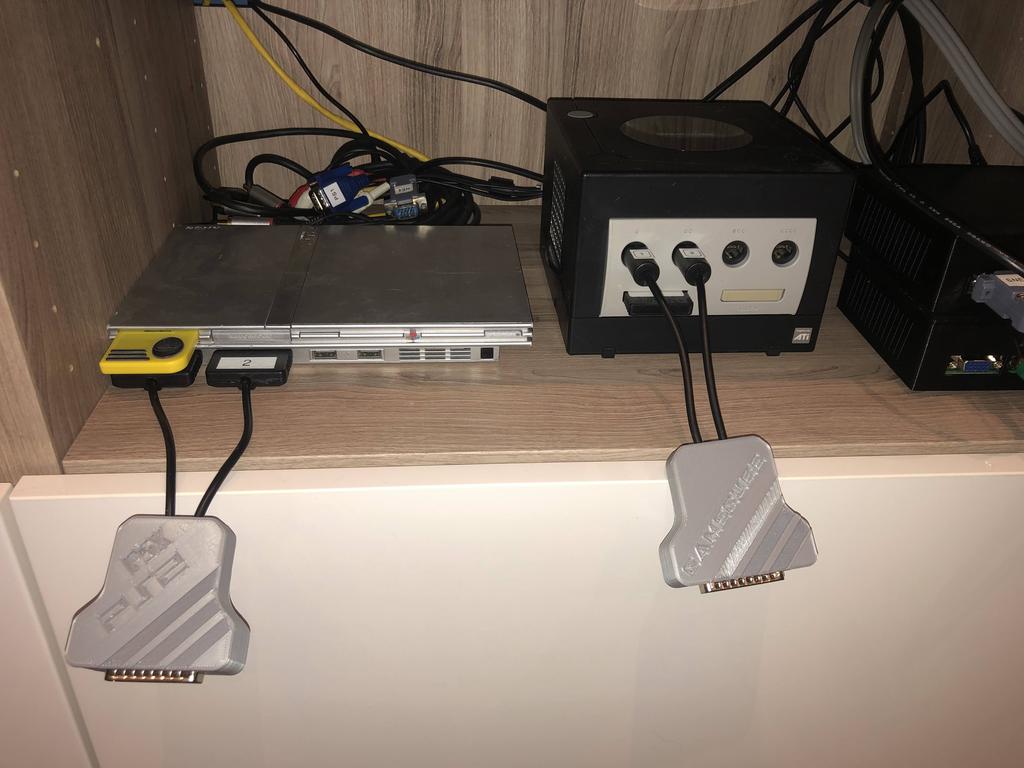
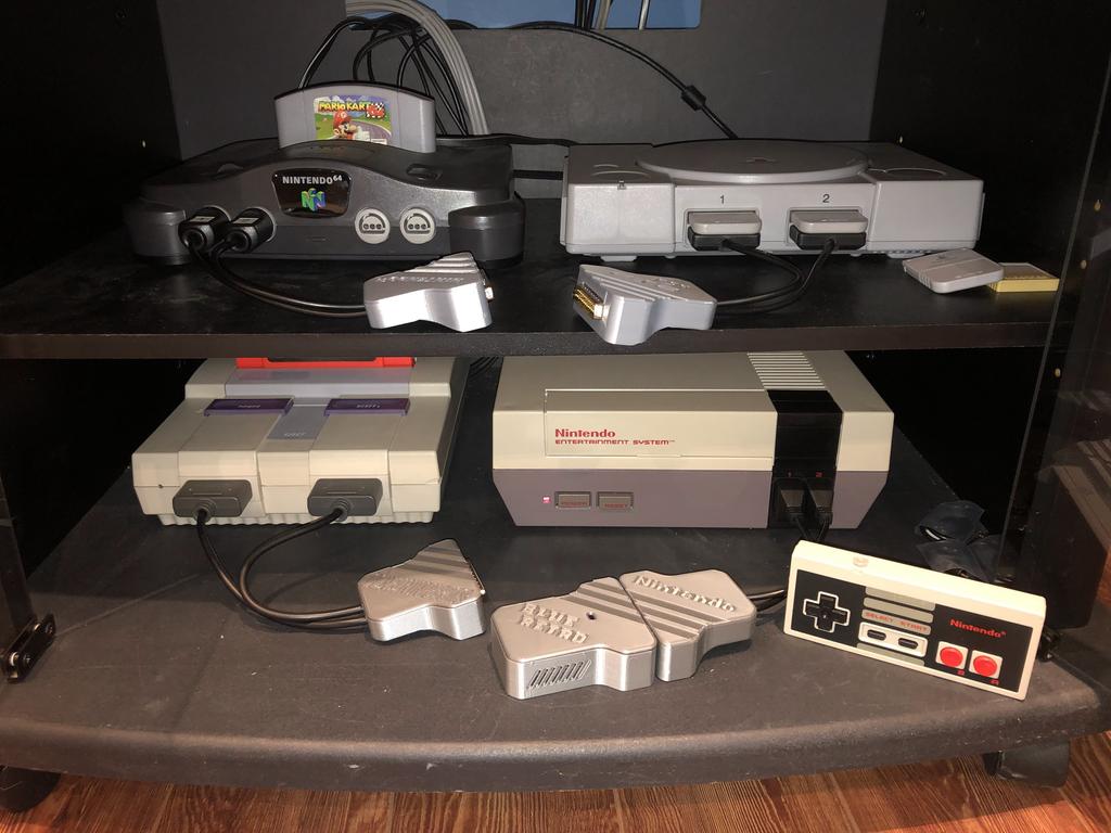
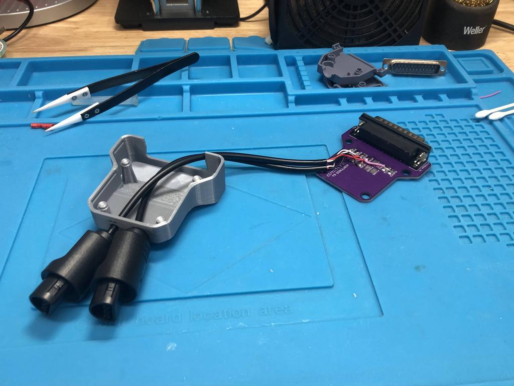
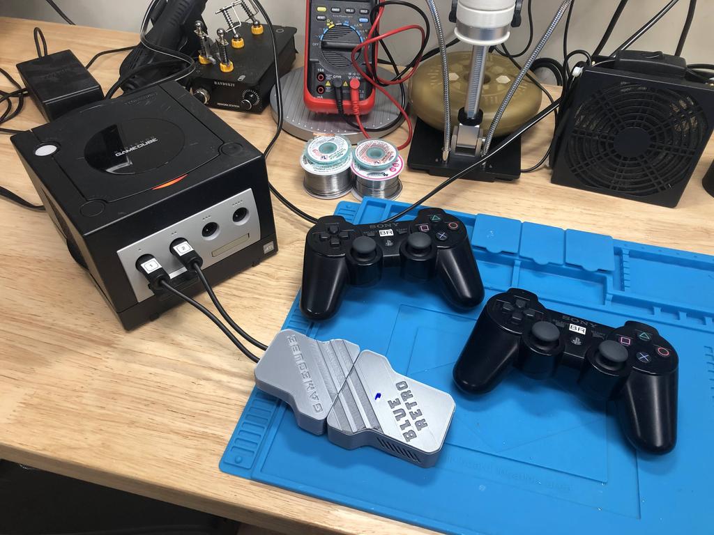
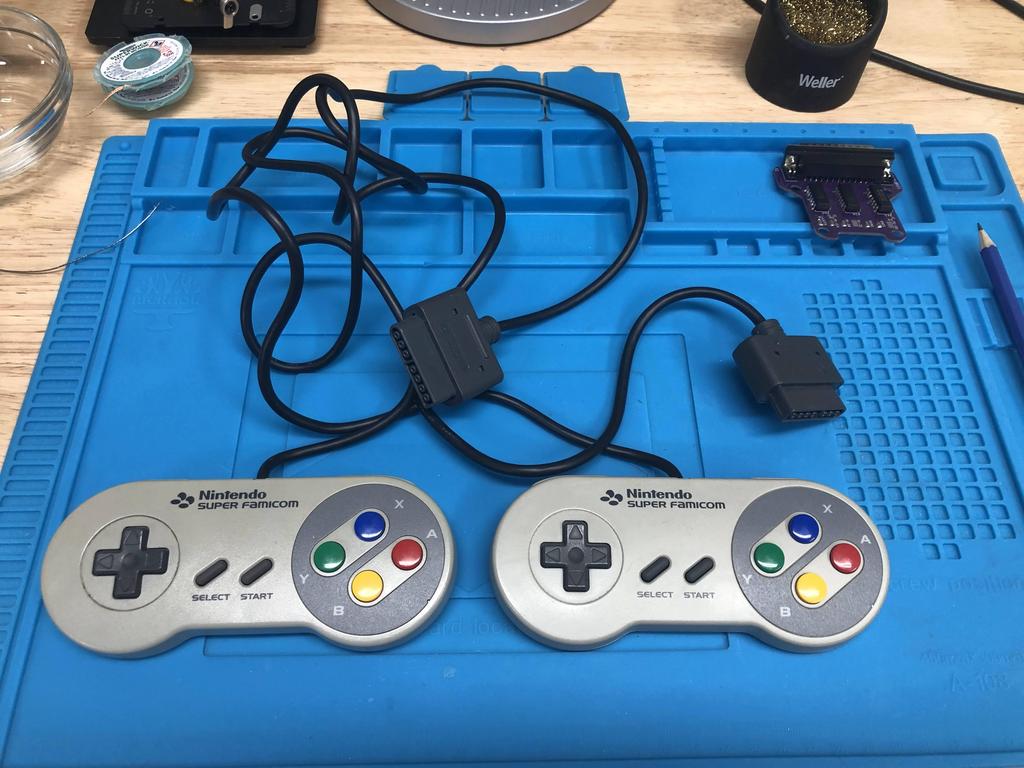
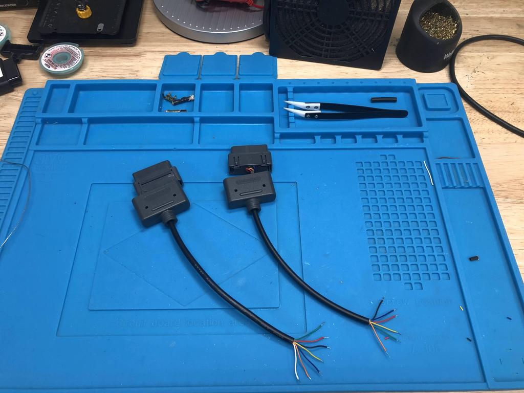
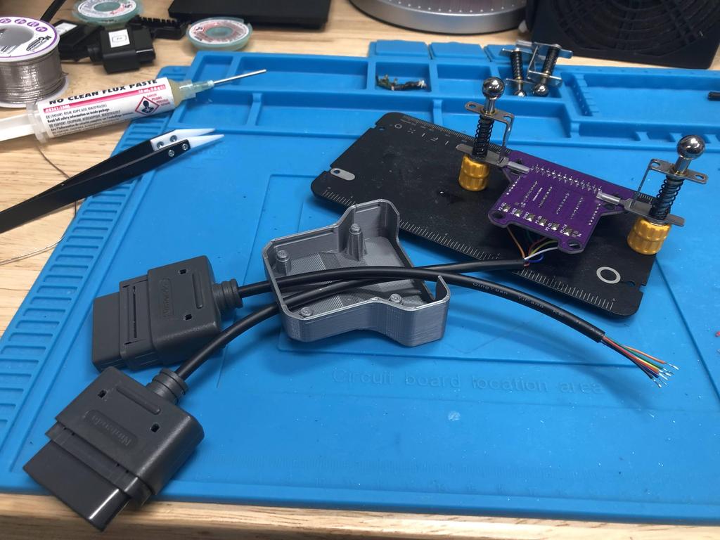
Before getting into how I made these AIO units, I thought I’d share what my final setup looks like with them, so that you know where we’re headed. I currently have 6 BlueRetro AIO adapters, and one receiver (connected to the NES adapter in these pics):
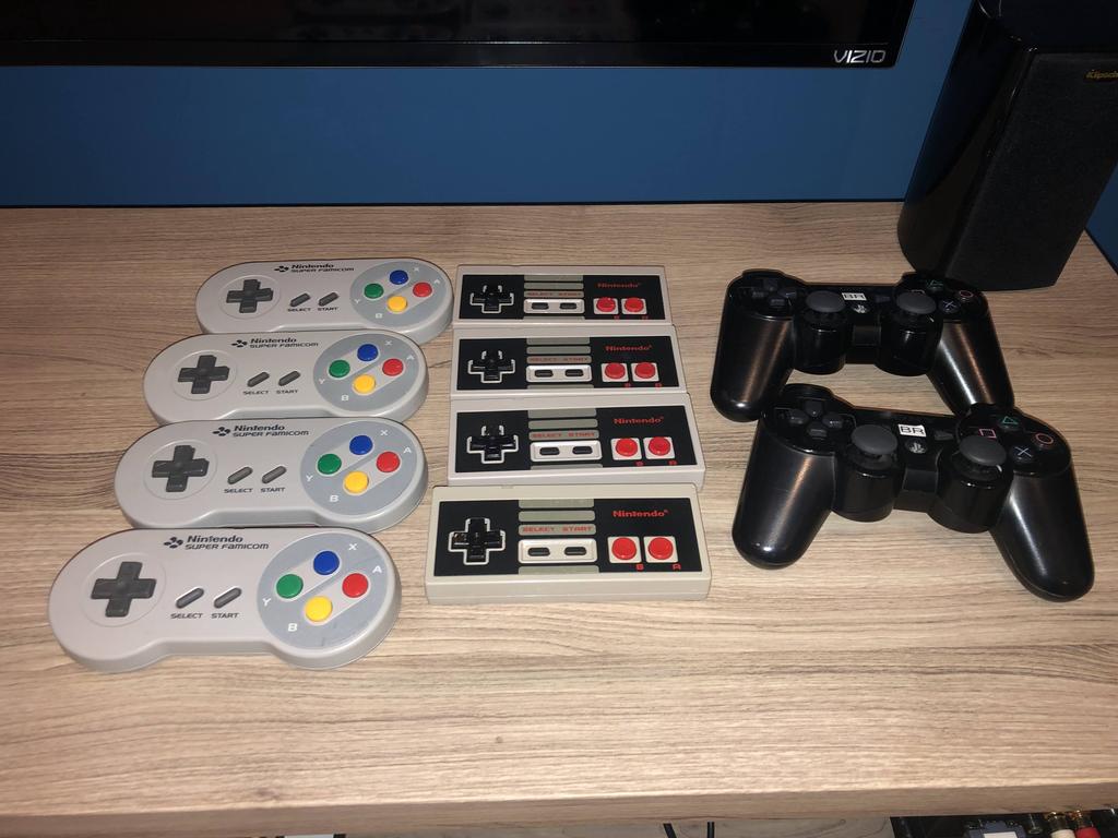
I also have an array of Bluetooth controllers as well:
When I want to play a different system, I simply disconnect and reconnect the receiver to that system’s adapter. It’s quick, and since I have only one receiver, I only have one device to configure and update.
Alright, let’s get into the how I made these.
Making BlueRetro AIO Units #
Making BlueRetro AIO units requires a few parts:
PCB
For the PCBs, I personally use JLCPCB because it’s cheaper for me than most other options. Simply download the Gerber files for the system you need, and uploaded them to JLCPCB, sticking to default options (except board color). Note that the BlueRetro “receiver” - the part that holds the ESP32 devkit board - is called “Main_<date>.zip”. The file names for each console-specific PCB has the name of the console in it (e.g. “SNES_<date>.zip”).
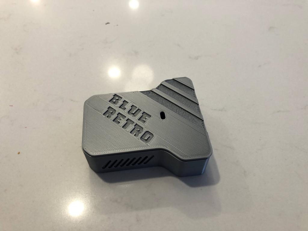
3D-printed shell
For the 3D-printed shells, the STL files can be downloaded from here. The way it works is that there are two parts, the top and the bottom. For the receiver, you’ll want to print this top and this bottom.
For each console adapter, select the top that’s specific to the console. The only difference here is that each one has a nice logo embedded into it (see the SNES one, for example). For the bottom part, you’ll need to choose from one of the “Aux Bottom - <N> Player.STL” files, where <N> is the number of controllers you intend to connect. This basically translates into how many holes the bottom case will have for the controller cables to pass through. You don’t have to match the number of ports on the target console; for instance, the N64 supports up to four controllers, but I decided to only connect two, as I don’t expect to play four player games. See this BOM for what you’d typically want to print for each console.
Controller cables and other components
Finally, you’ll also need controller cables, and depending on the console, potentially some other components, such as through-hole level-shifter ICs. For controller cables, I normally buy extension cables from AliExpress that I can cut, keeping the console plug side intact. See this very detailed BOM for the parts you’ll need per console.
The Builds #
Receiver #
Let’s start with the receiver, which is the part that connects to each adapter.
Parts:
- 3D printed shell
- PCB
- ESP32-DEVKITC-32E (aka ESP32-WROOM-32E)
- DB25 connector (female, 90 degrees)
- 2x 19 position pin sockets
- Optional:
- Blue LED (470nm 3.3V 1206)
- 84.5 ohm resistor (SMD 1206)
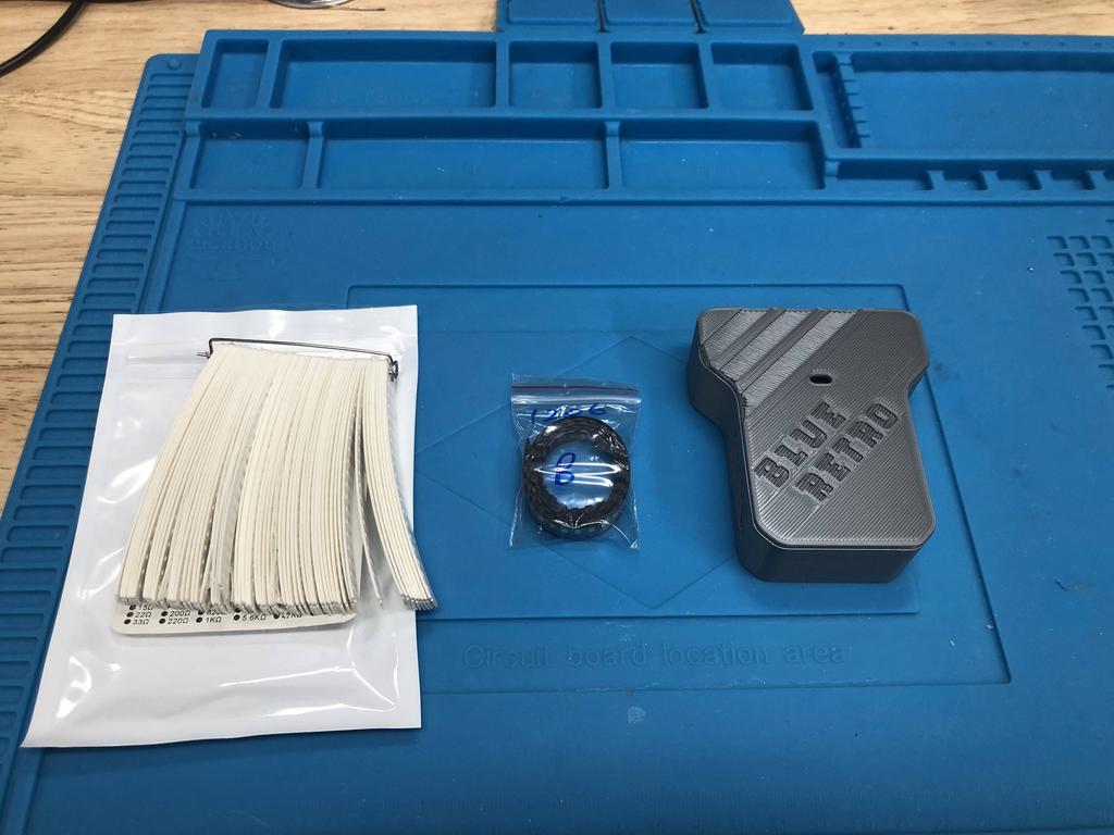
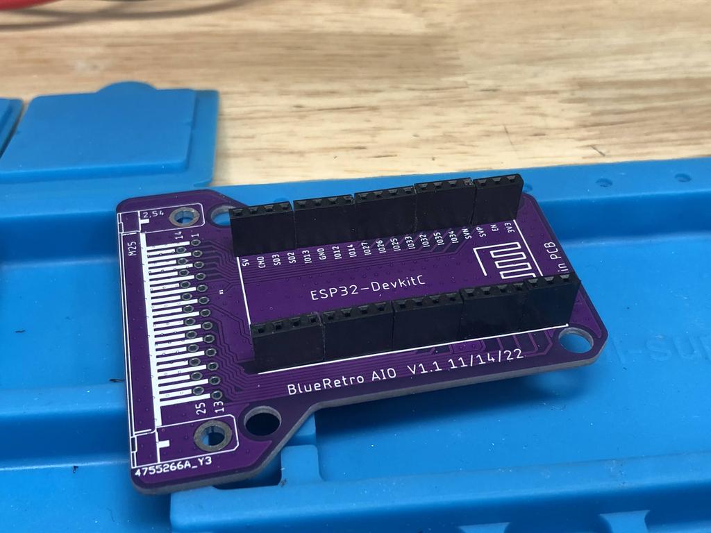
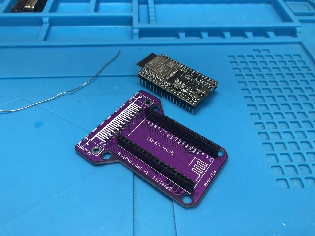
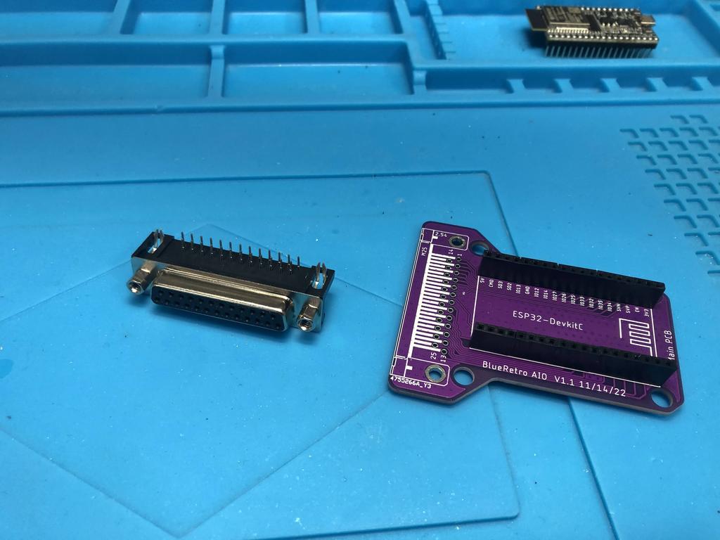
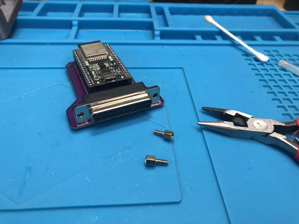
Here are the main parts:
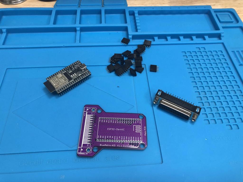
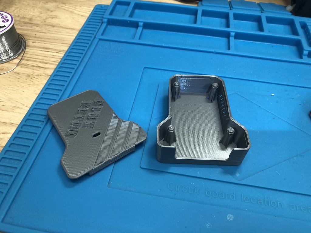
Along with the 3D-printed shell:
And the optional LED and resistor:
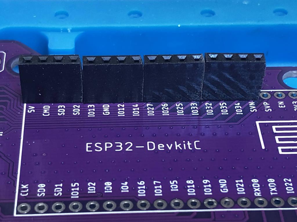
To save money, instead of buying two 19-pin sockets, I bought a bunch of 4-pin ones from AliExpress. Unfortunately, when inserting them into the PCB, I realized that they didn’t quite fit well together:
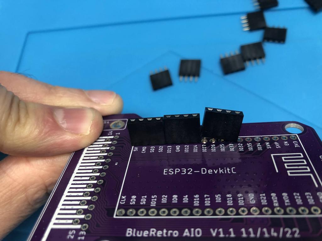
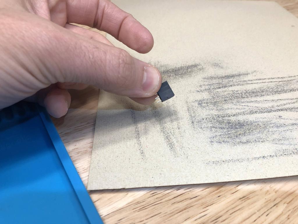
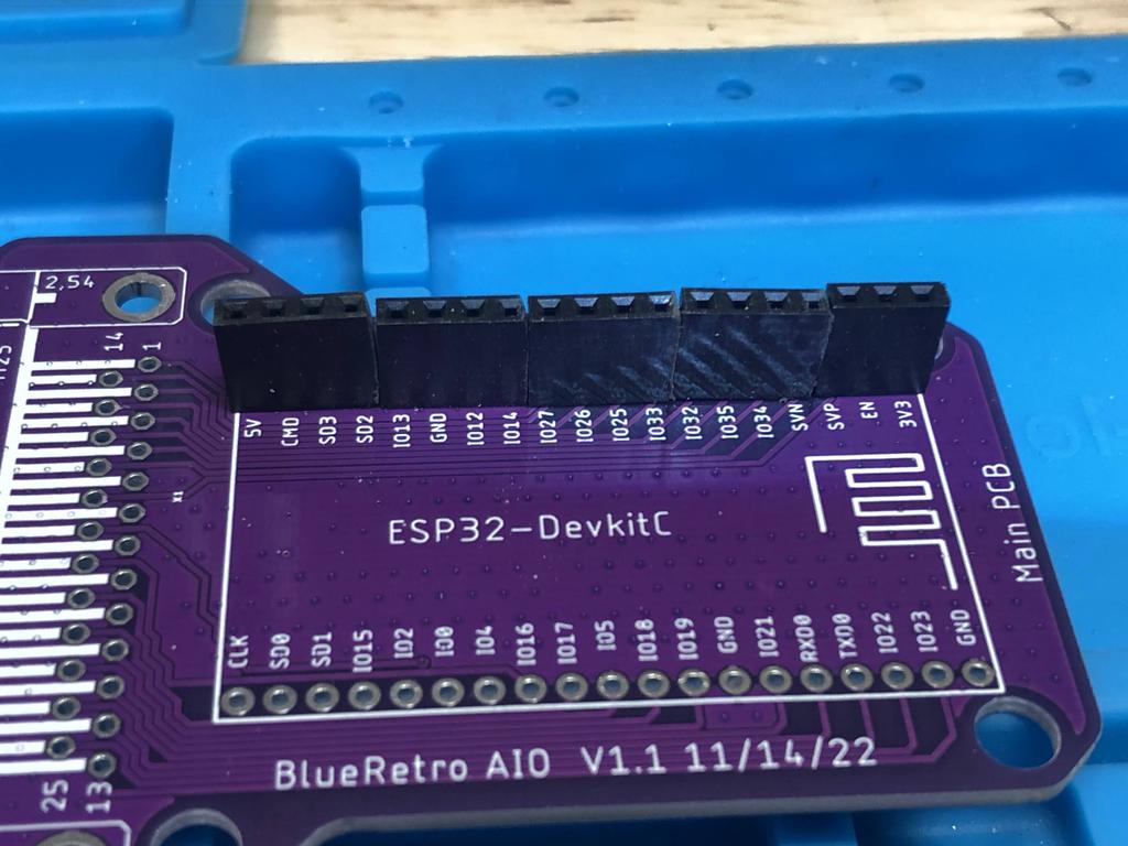
So I ended up filing the edges of each one with some sandpaper until they fit well enough:
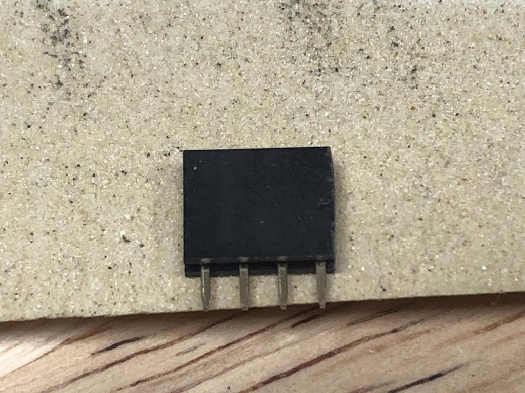
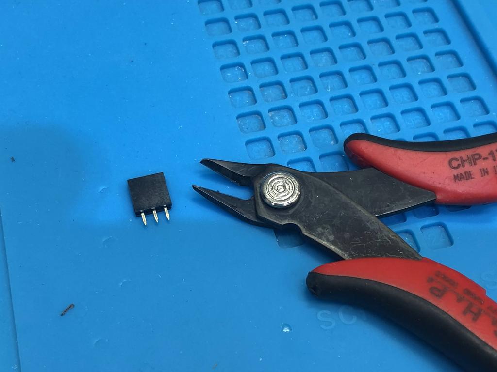
After inserting 4 of them on one side, the last one needed to be 3 pins wide, so I cut off the extra one with flush cutters:
I did the same for the other side, and to hold everything in place, I inserted the ESP32 board into them:
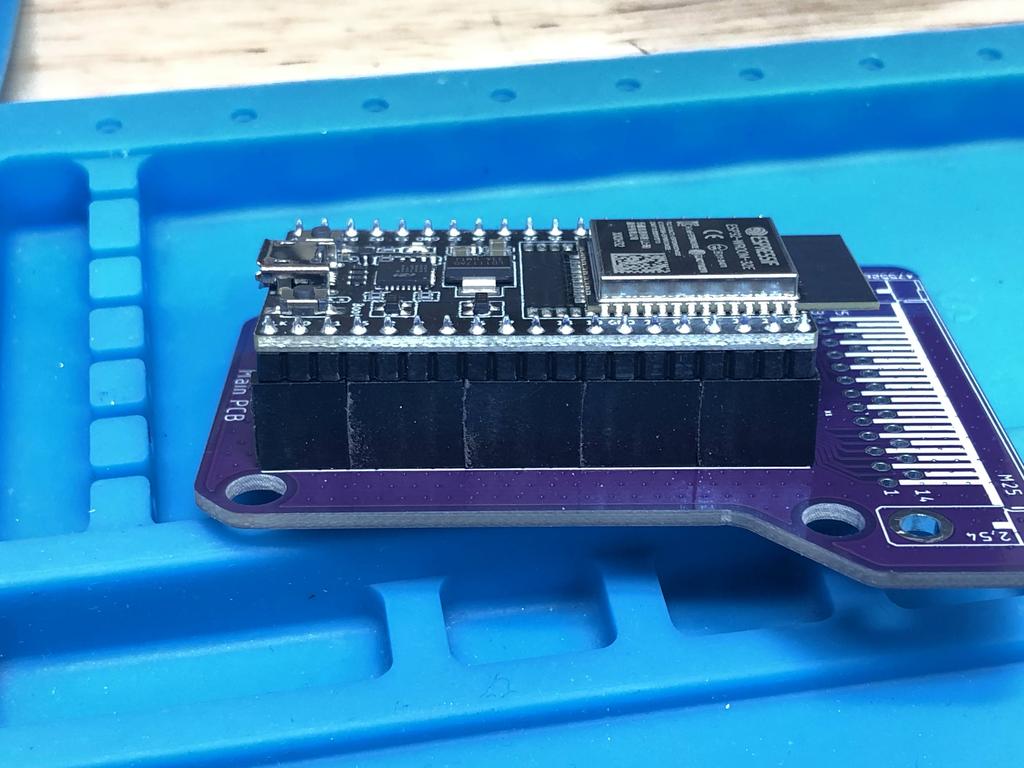 (Note that the ESP32 board is actually inserted the wrong way in the pic above, as this was only temporary to solder in the sockets).
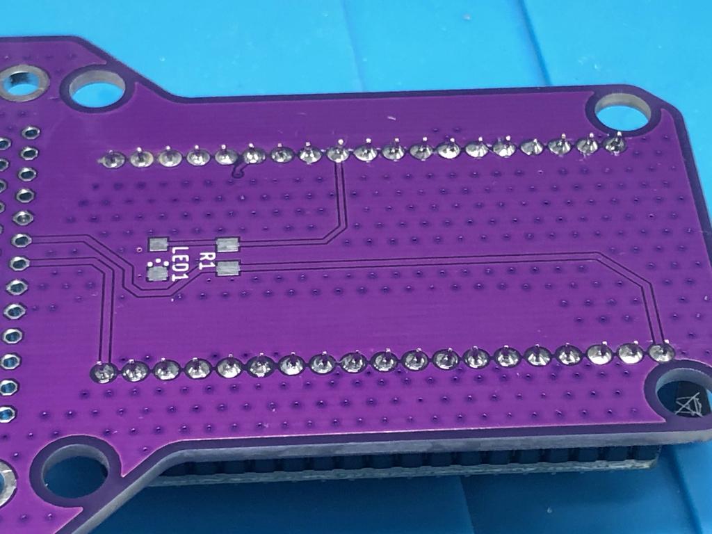
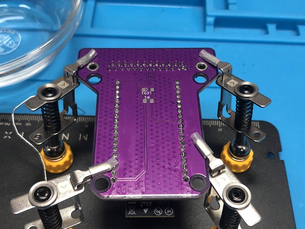
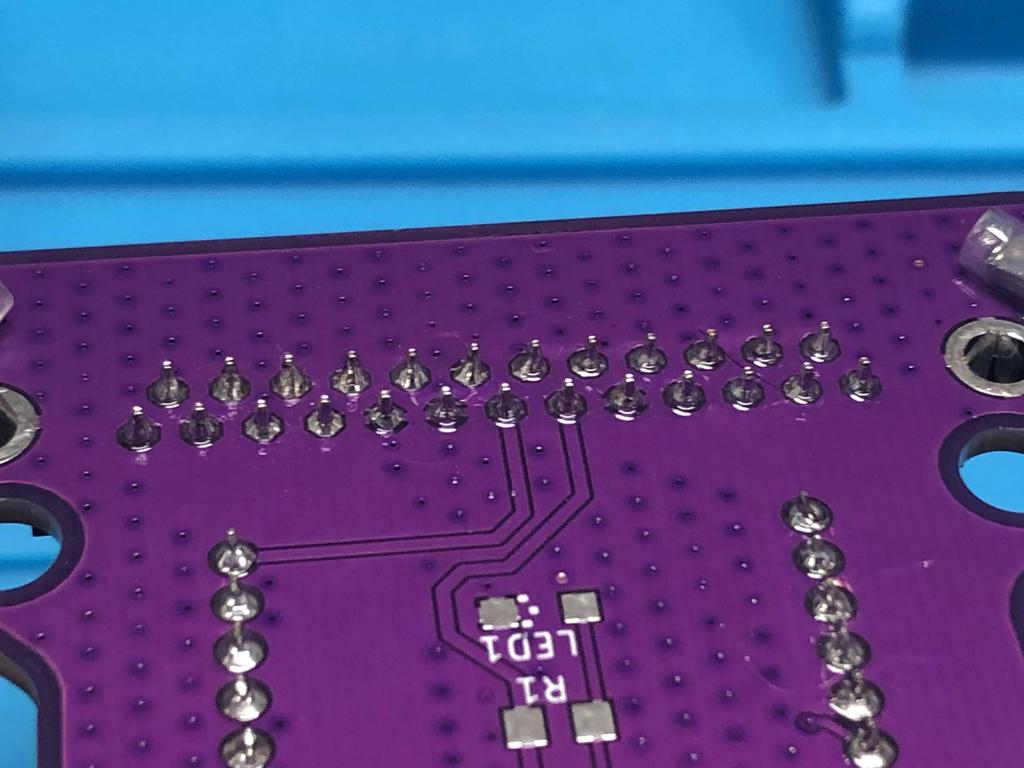
I soldered the pins to the underside:
This worked out okay, but I would recommend just getting the 19-pin sockets instead.
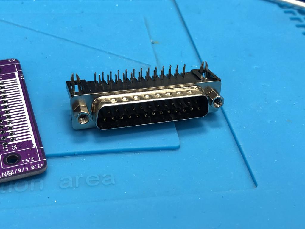
Next, I soldered the female DB25 connector to the PCB. Note that the AIO BOM suggests using a male connector for the receiver, and female ones for each console adapter. I went the opposite way, which is totally fine:
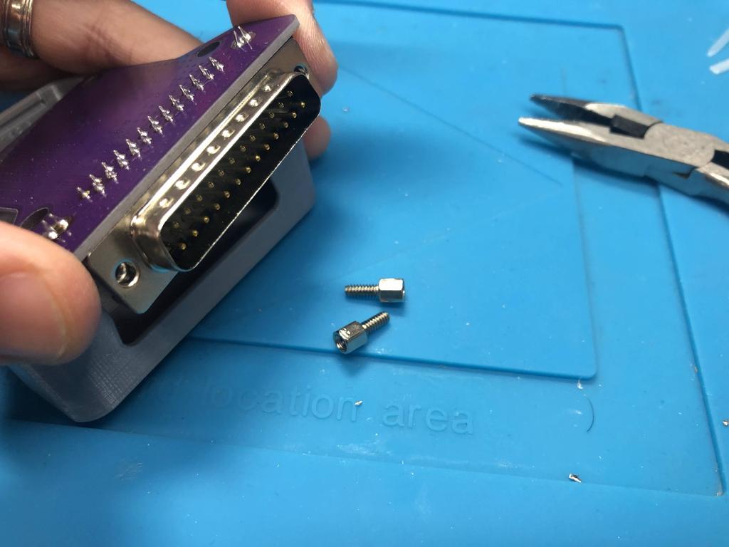
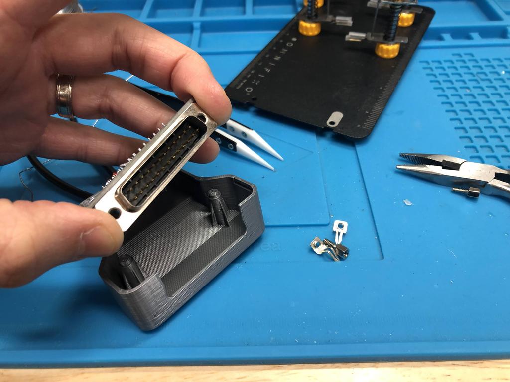
I removed the two screw posts from the DB25 connector. The 3D printed shells are made such that these posts should be removed, though the metal plate that is held by the screw posts is kept:
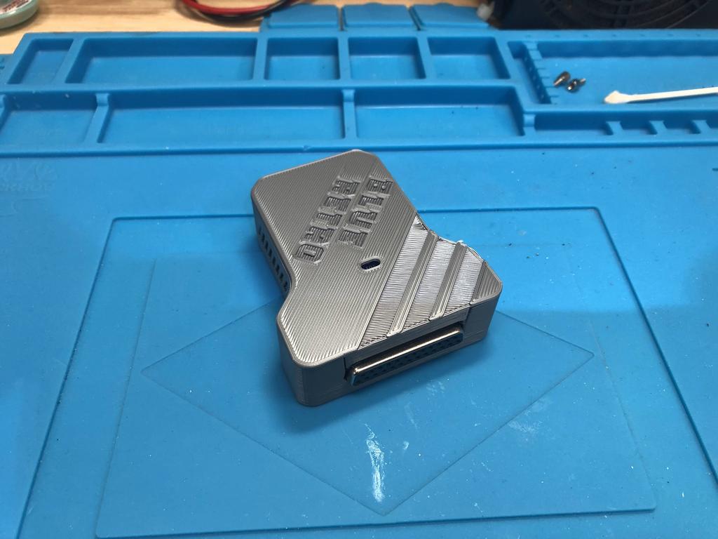
Finally, I placed the board into the shell, and closed it up:
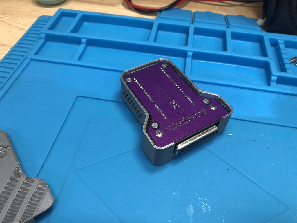
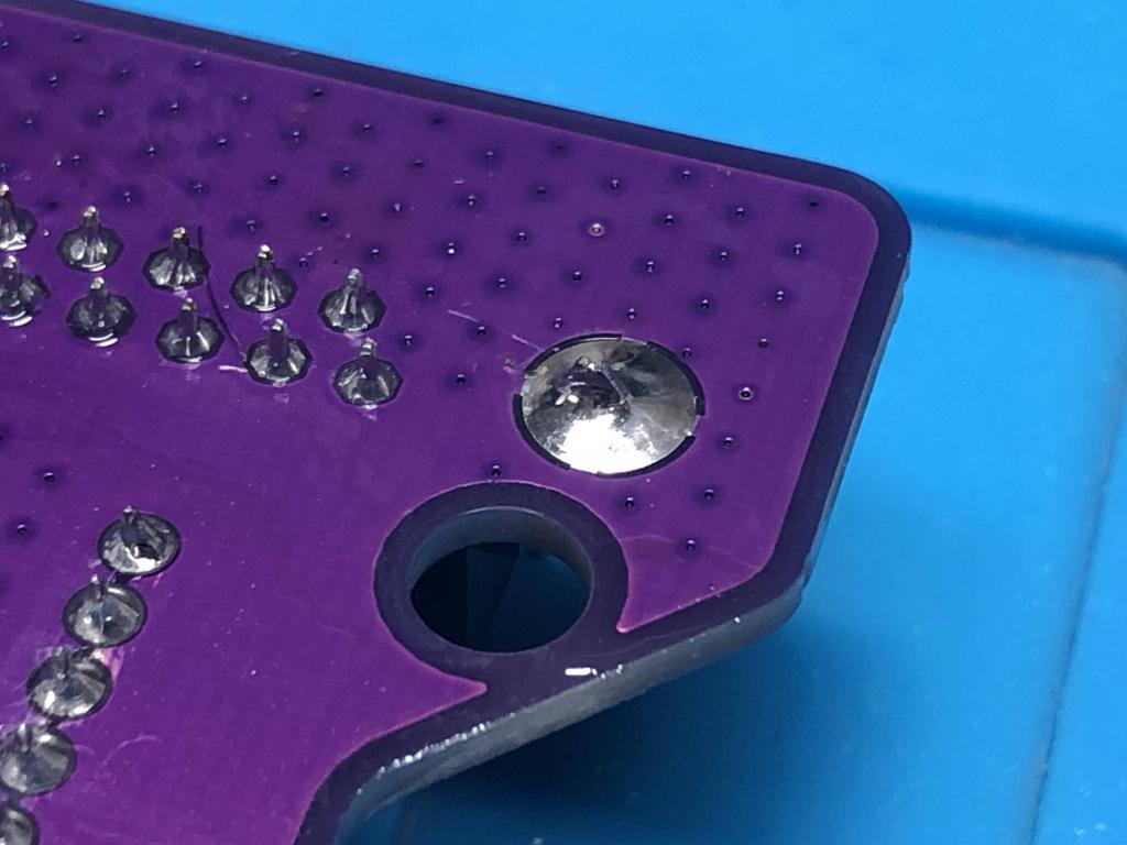
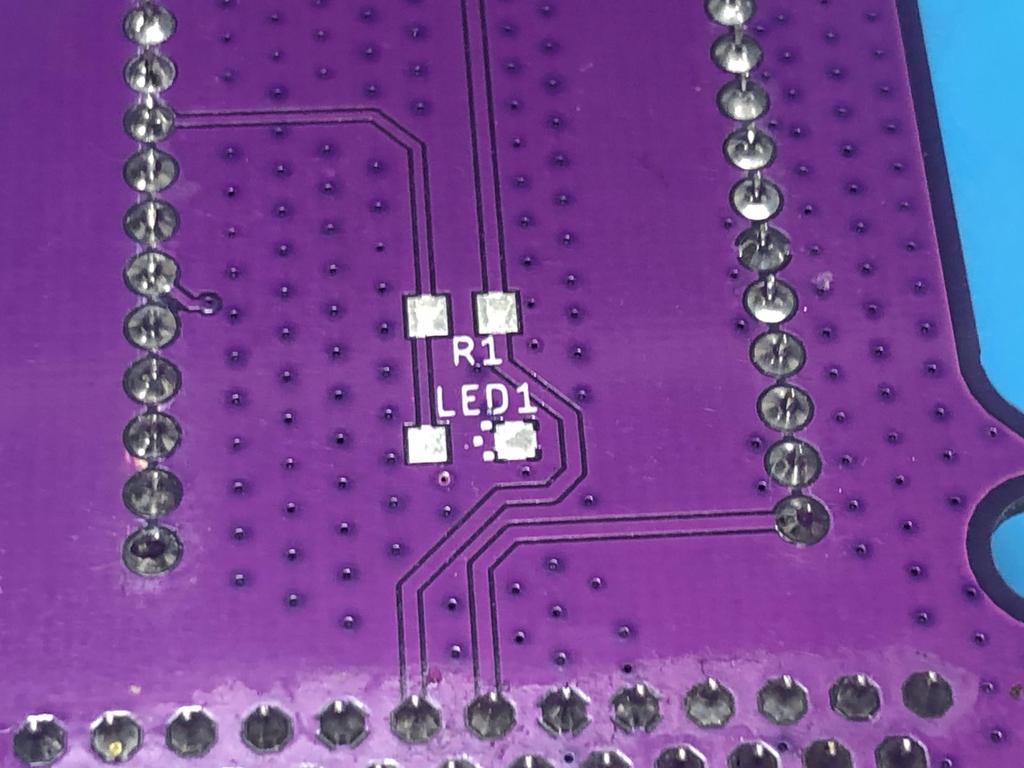
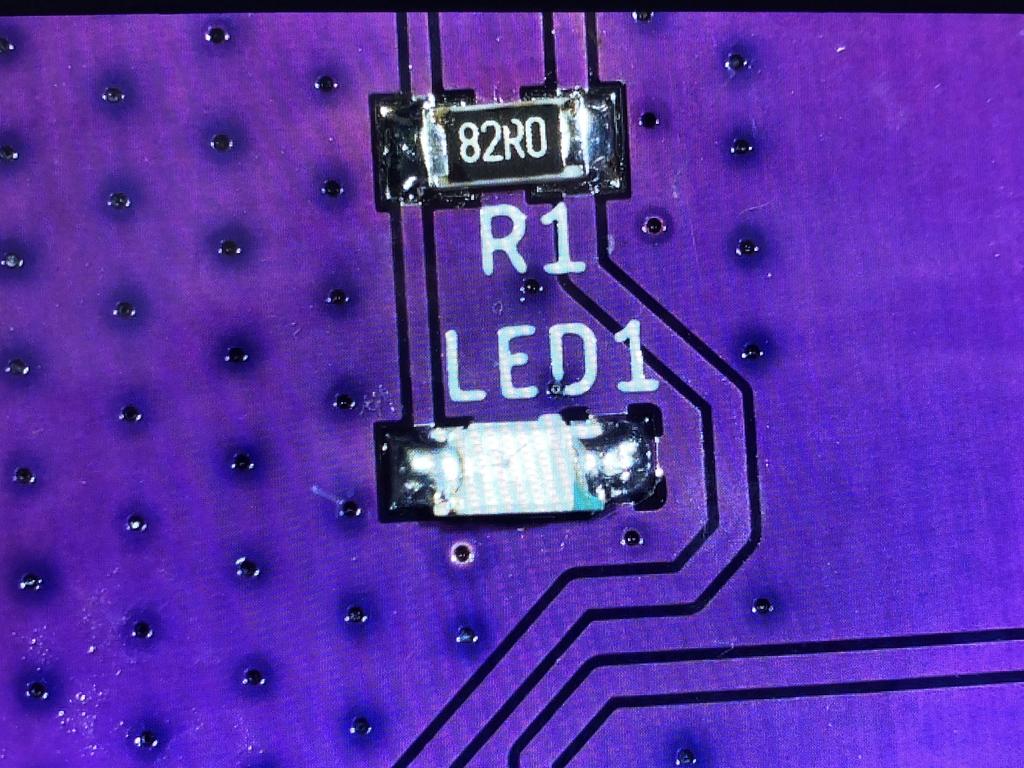
At this point, we can stop. However, I got the optional LED and resistor, which are useful for showing the status of the BlueRetro receiver (e.g. it flashes in pairing mode). I soldered on the LED and the resistor to the underside of the PCB:
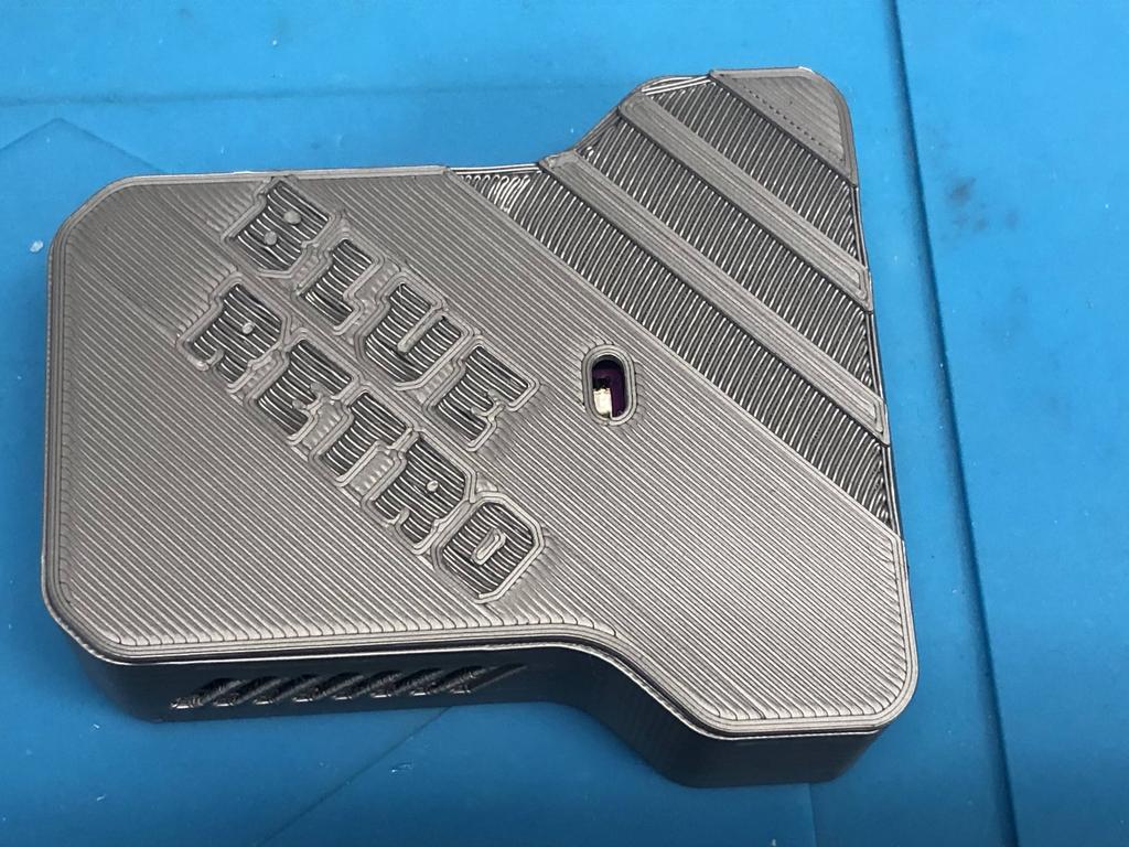
The LED shows through the hole in the 3D-printed cover:
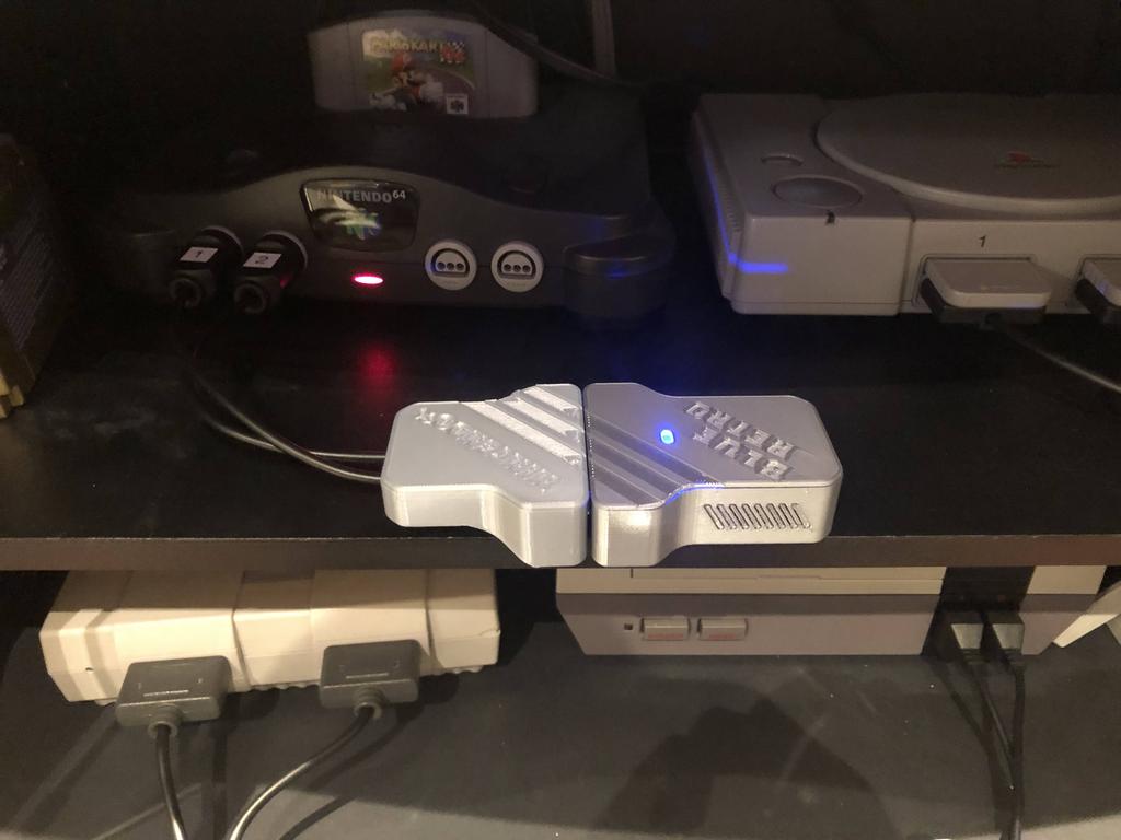
Here it is in action:
N64 #
The N64 is probably the easiest adapter to build, so let’s start with that one.
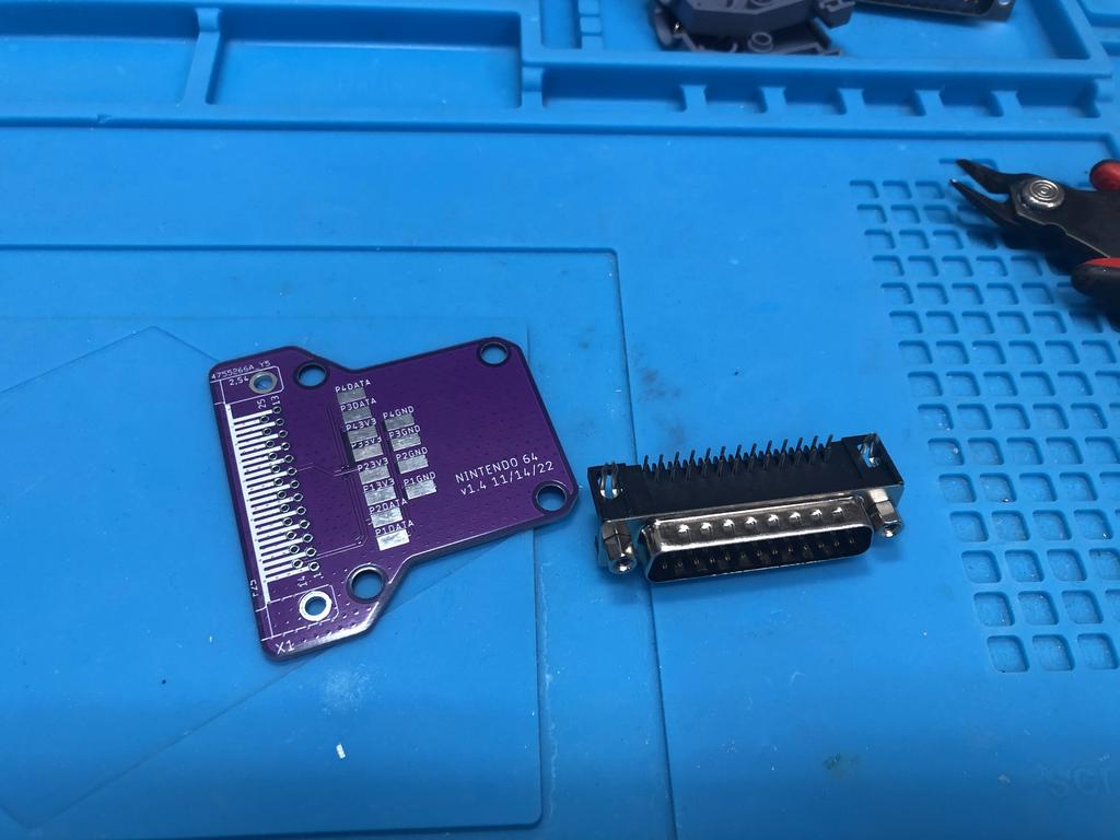
Parts:
- PCB
- 3D-printed shell
- DB25 connector (male, 90 degrees)
- N64 extension cables (1, 2, or 4)
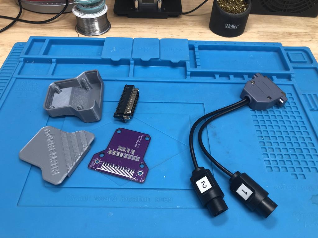
The N64 supports up to 4 controllers, but as I don’t expect to play 4 player games very often, I decided to only build a 2-player adapter.
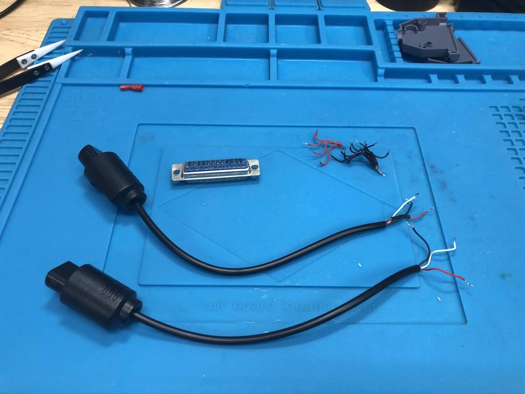
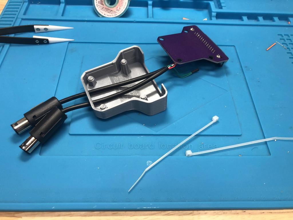
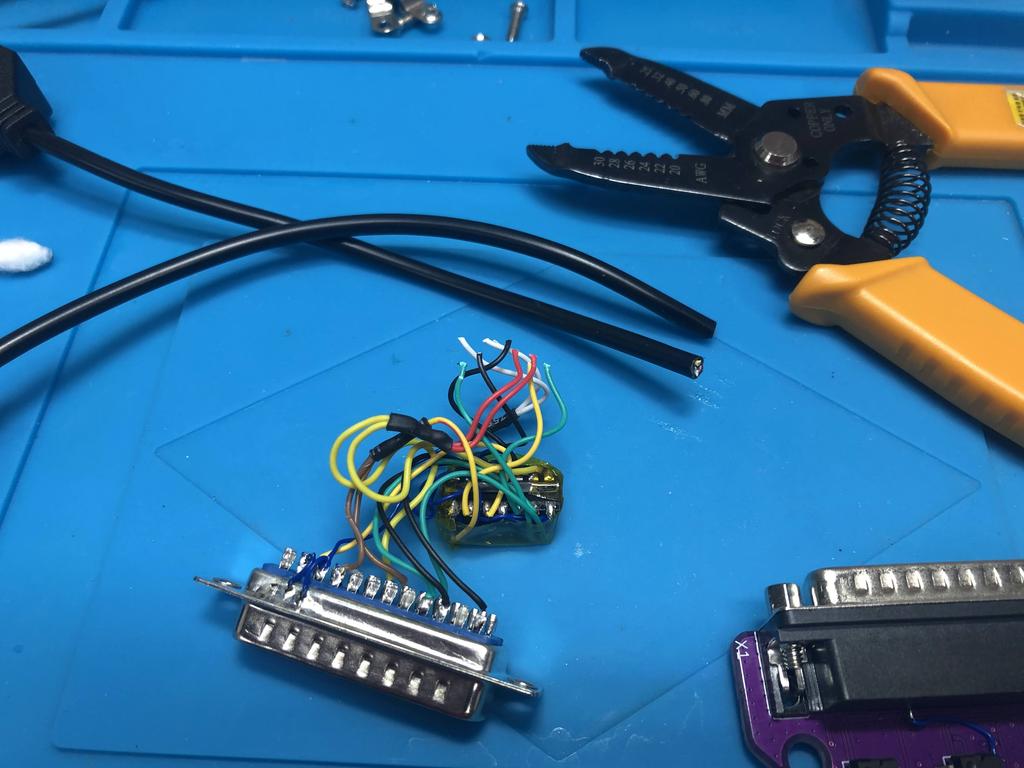
First, I undid my existing DIY adapter. If starting from scratch, you’d want to cut and strip the ends of the extension cables, and tin each end:
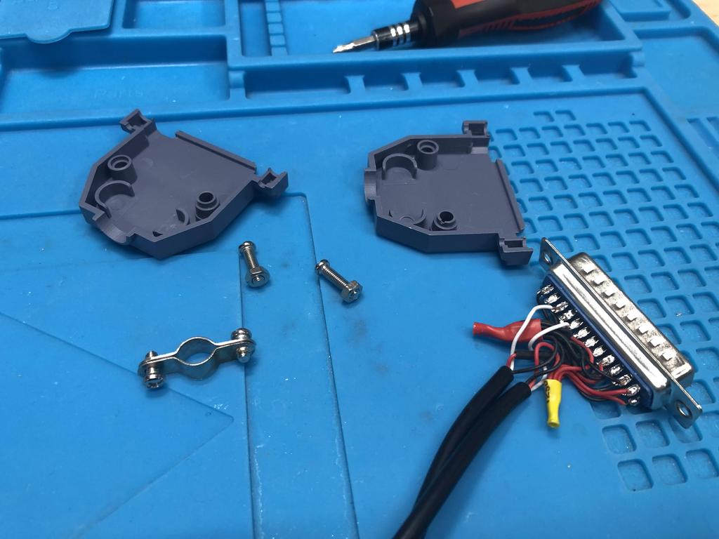
I inserted the two cables into the 2-player bottom shell:
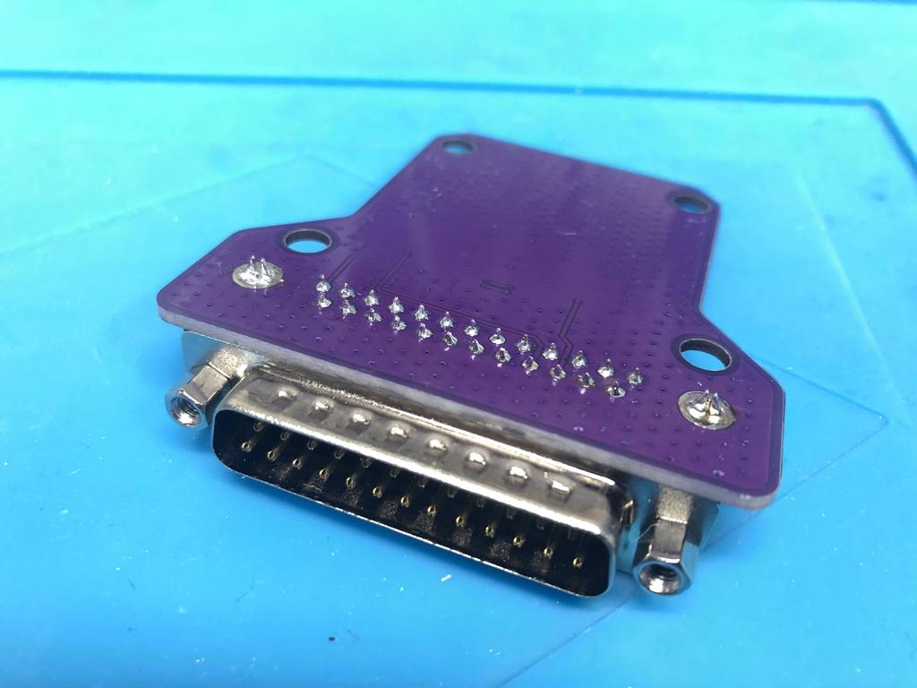
I then soldered the DB25 connector to the PCB:
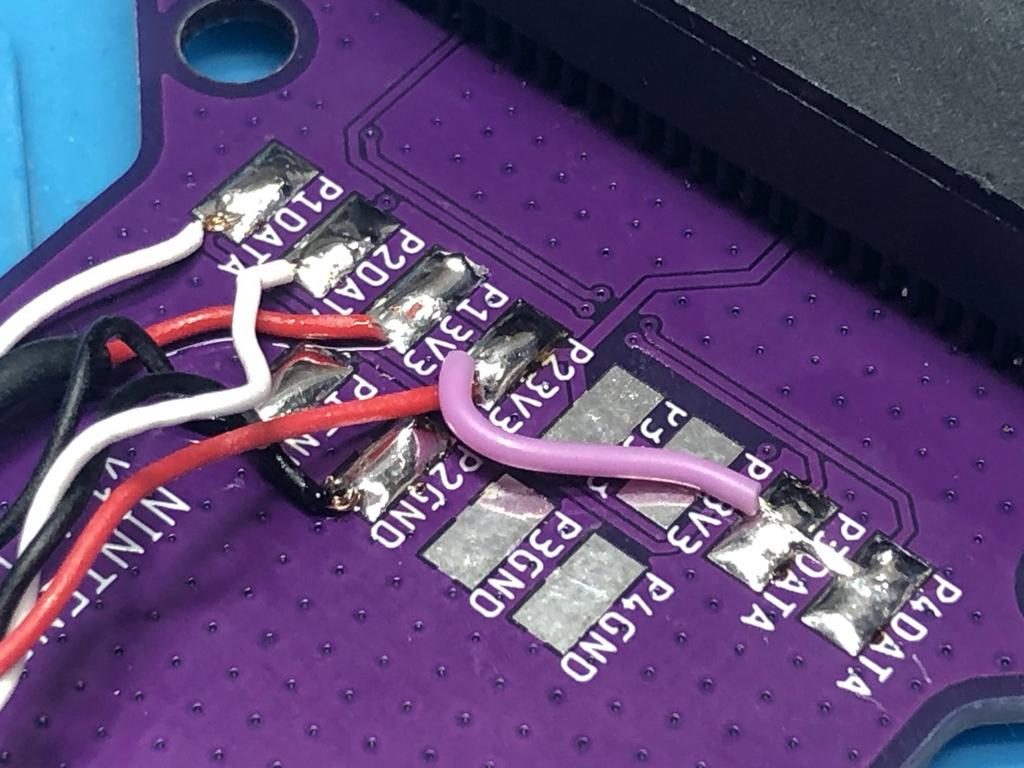
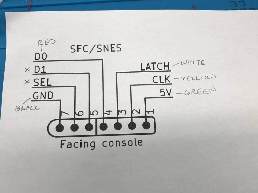
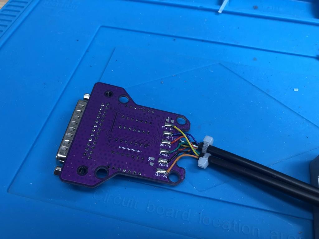
Next up was wiring the cables to the PCB. I referred to the schematic I had printed before where I had identified which color wire each of the three pins mapped to:
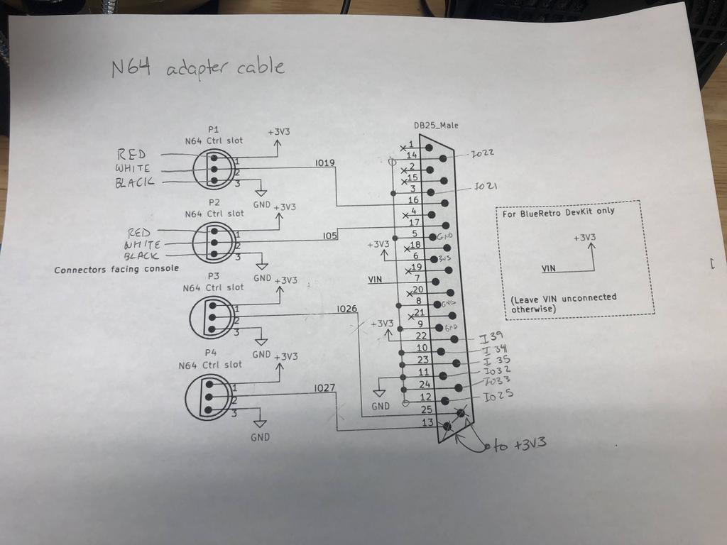
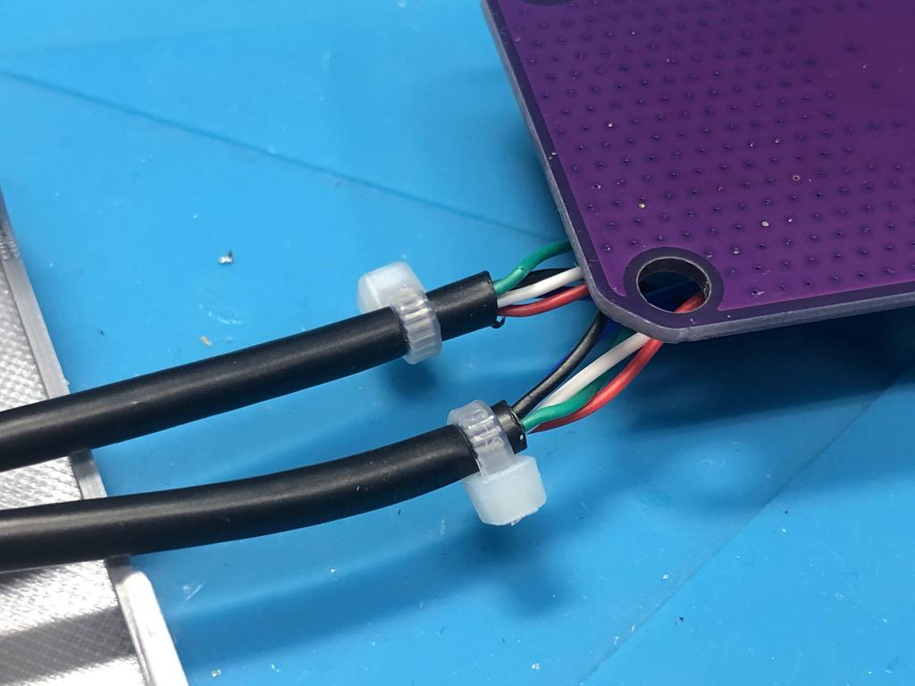
In my case, white is data, red is 3V3, and black in ground. So I soldered the three wires from the first controller to P1DATA, P13V3, and P1GND respectively. I then did the same for the second controller:
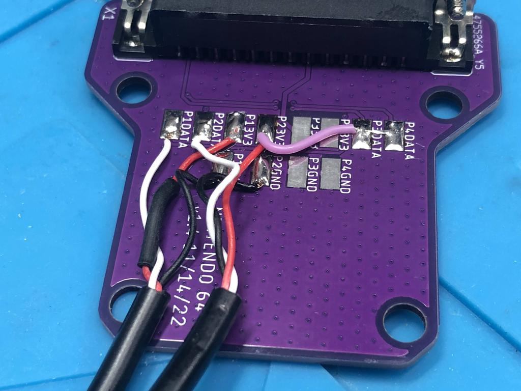
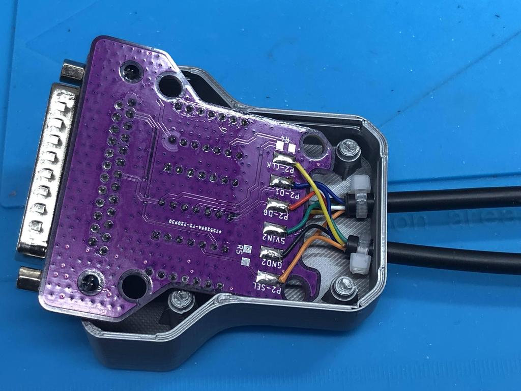
Since I decided not to connect player 3 and player 4 cables, as per the assembly instructions, I needed to connect P3DATA and P4DATA to 3V3. This is how the BlueRetro knows that these are not connected. I did this by soldering a short (pink) wire to P23V3 on one end, and the other end to both P3DATA and P4DATA:
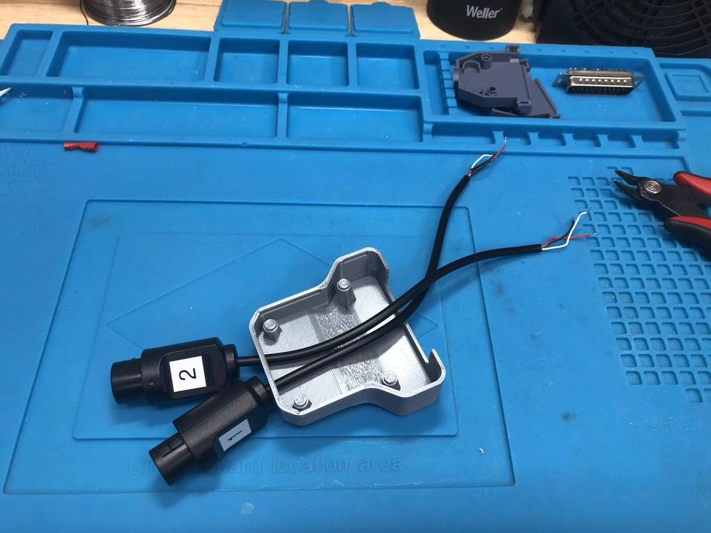
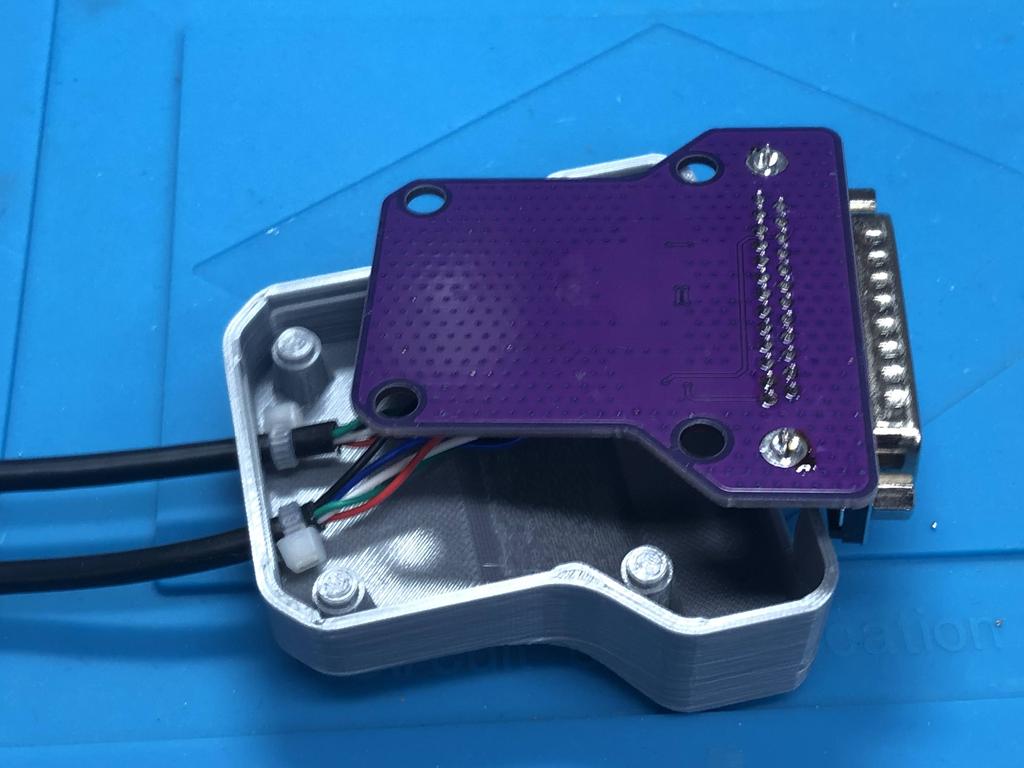
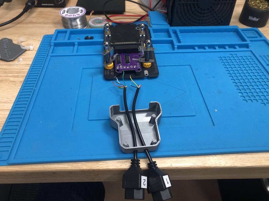
With the wiring done, it was time to put it all together:
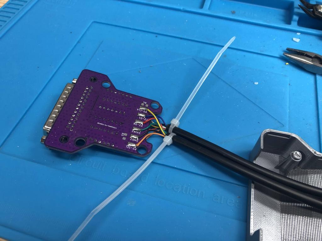
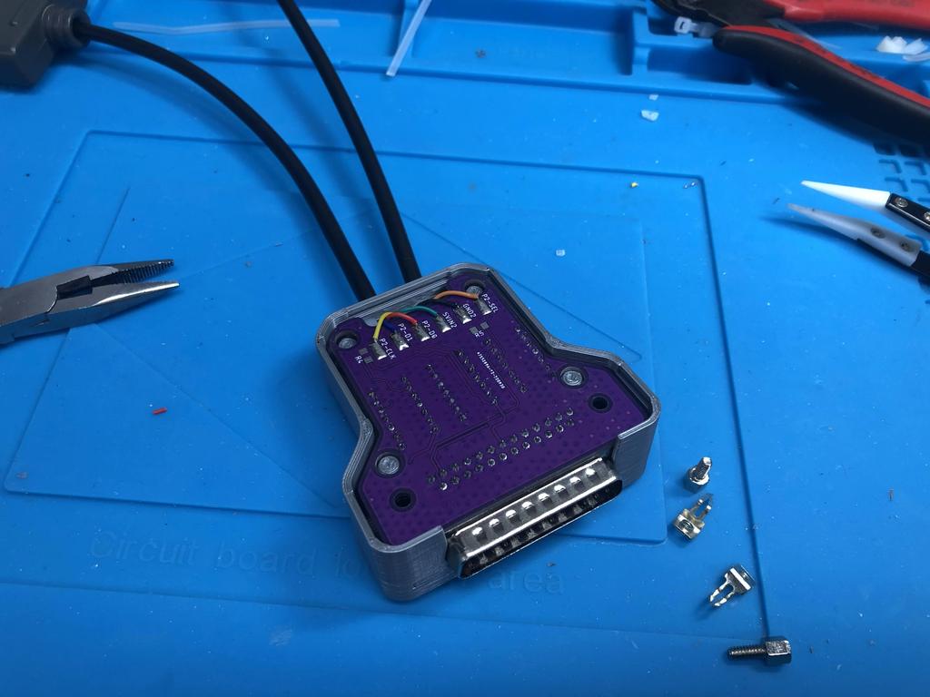
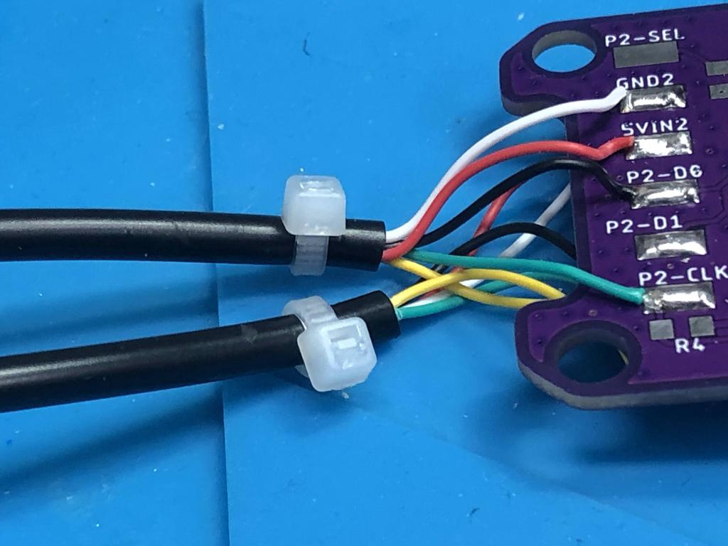
To avoid the wires being ripped off the PCB, I used a couple of small zip ties that I tied very tightly to the ends of the cables:
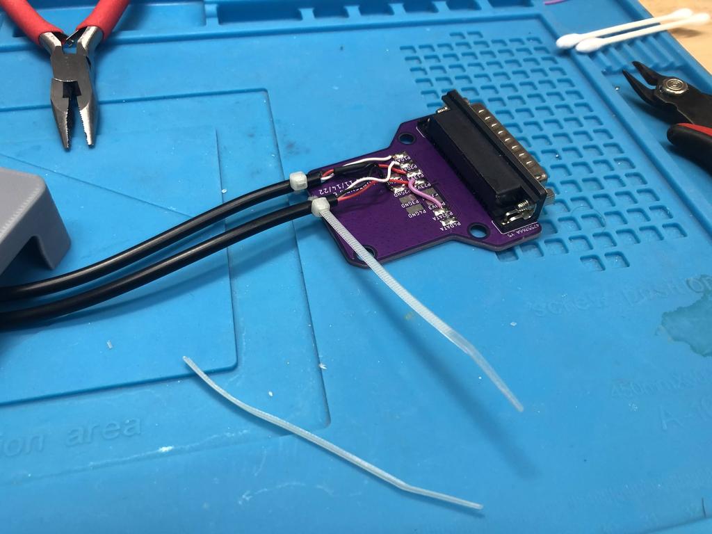
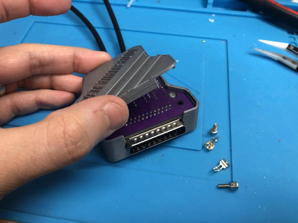
I then threaded the cables out, positioned the PCB in the shell, and closed it all up:
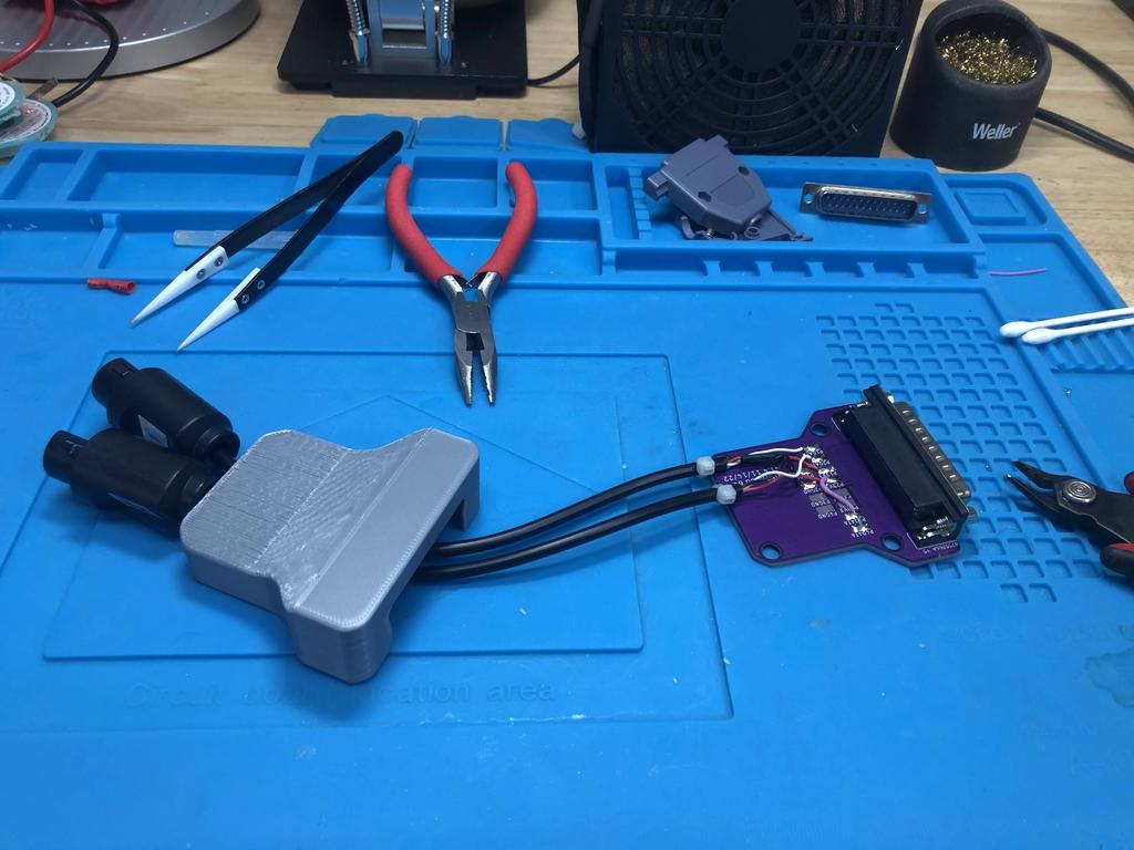
Done!
GameCube #
The GameCube adapter is about as easy as the N64 one, only with a few more wires to solder.
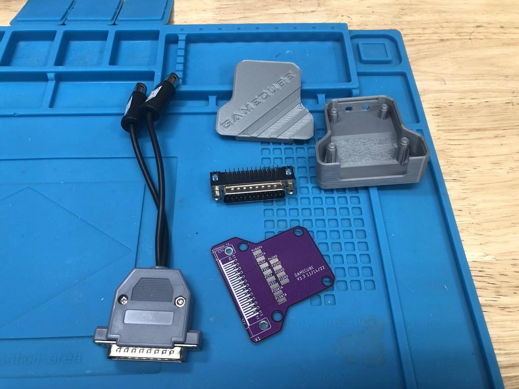
Parts:
- PCB
- 3D-printed shell
- DB25 connector (male, 90 degrees)
- GameCube extension cables (1, 2, or 4)
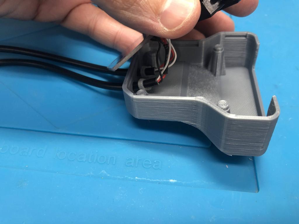
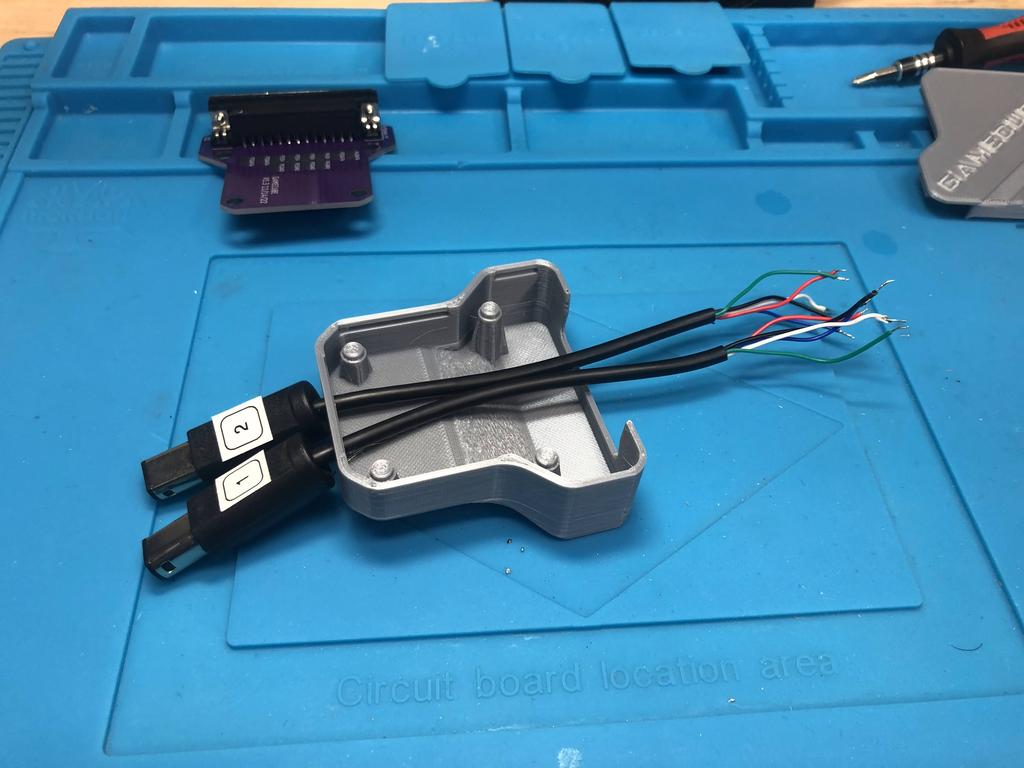
First, I undid my existing adapter. If starting from scratch, you’d want to cut and strip the ends of the extension cables, and tin each end:
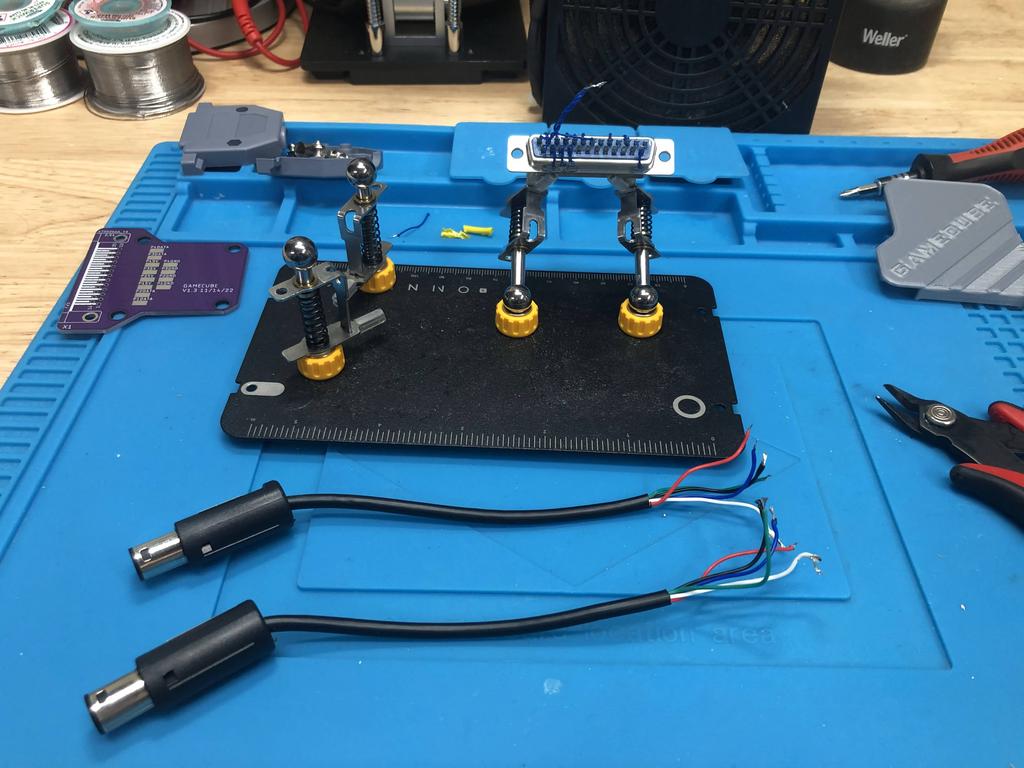
I inserted the two cables into the 2-player bottom shell:
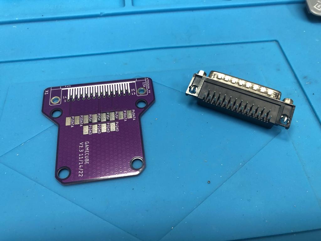
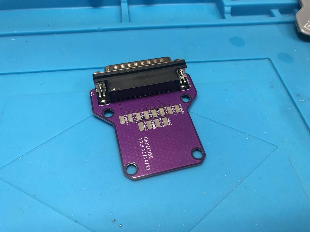
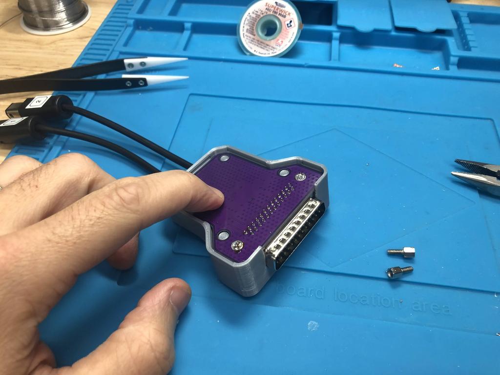
Next, I soldered the DB25 connector to the PCB:
Now for wiring the cables to the PCB. I referred to the schematic I had printed before where I had identified which color wire each of the three pins mapped to:
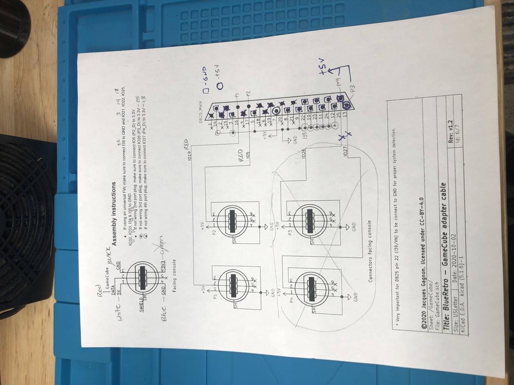
In my case, red is DATA, white is 5V, black and blue are GND, and green is 3V3, which is not used in this adapter.
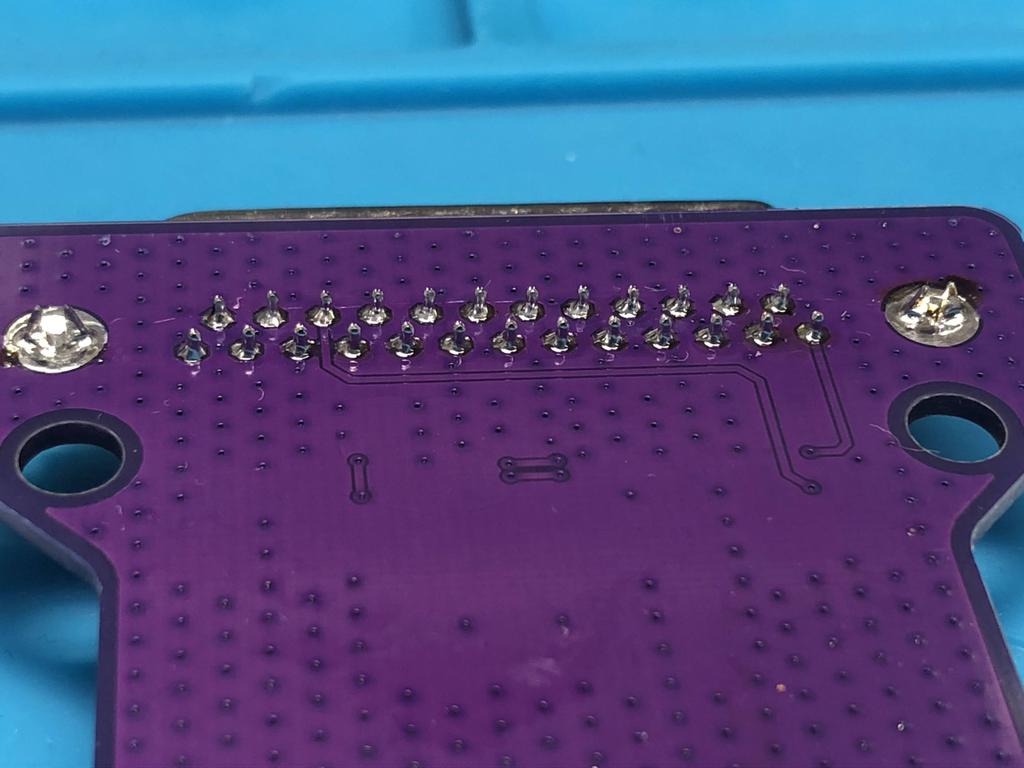
I started off by soldering the black and blue GND wires for player 1 and 2 to their respective pads, P1GND and P2GND:
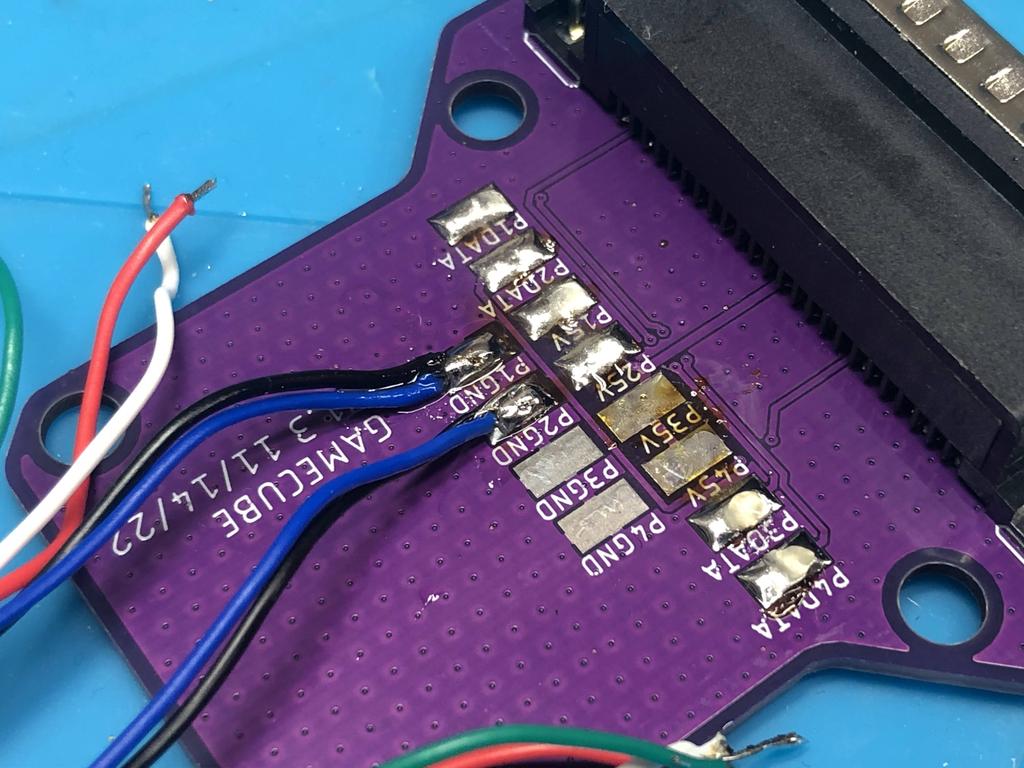
I then soldered the rest of the wires, player 1 red and white to P1DATA and P15V, and player 2 red and white to P2DATA and P25V:
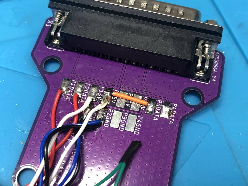
Similar to the N64 adapter, because I wasn’t connecting player 3 and 4 cables, I needed to connect P3DATA and P4DATA high, so I used a short piece of orange wire to connect these two pads to P25V. Note that the assembly instructions actually say to connect these to 3V3, which I could have done by hooking up the 2 green wires to these two pads; but the ESP32 module should be able to handle the 5V on these two pins.
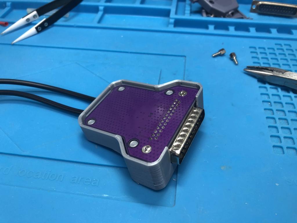
With the wiring done, I used zip ties to create strain reliefs:
Once again, the screw posts on the DB25 connector need to be removed, though the metal face plate remains:
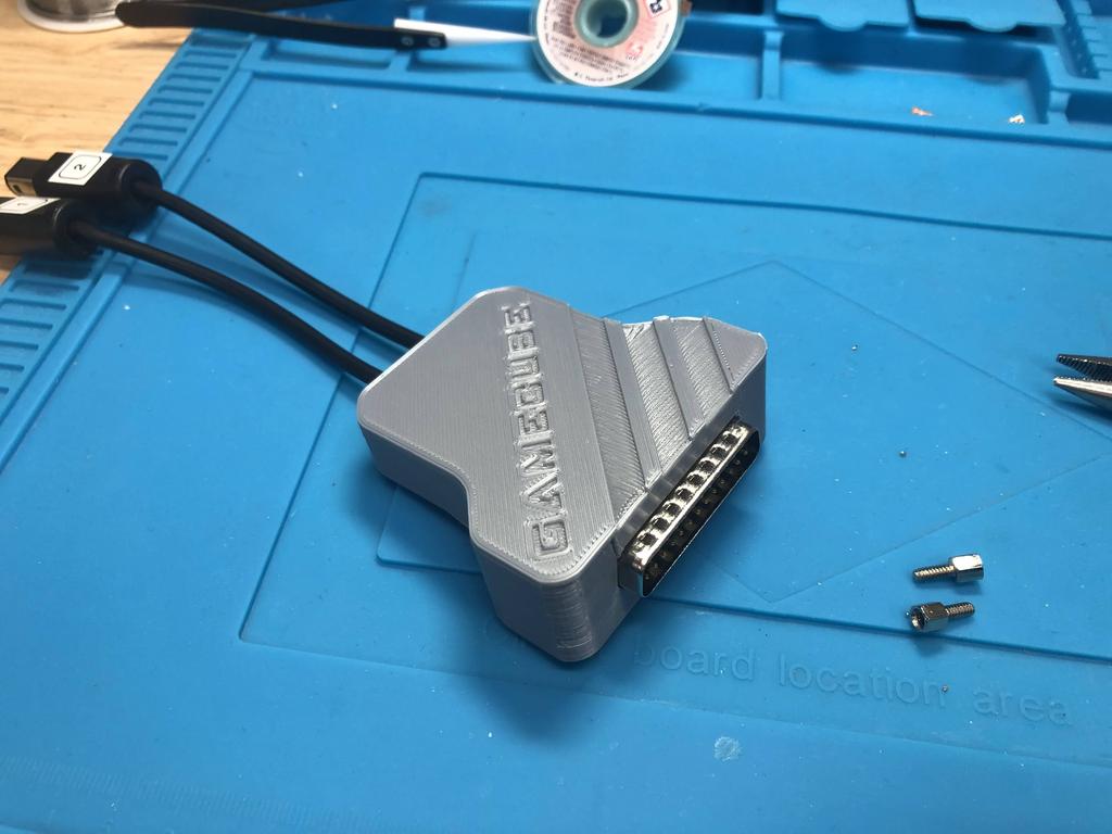
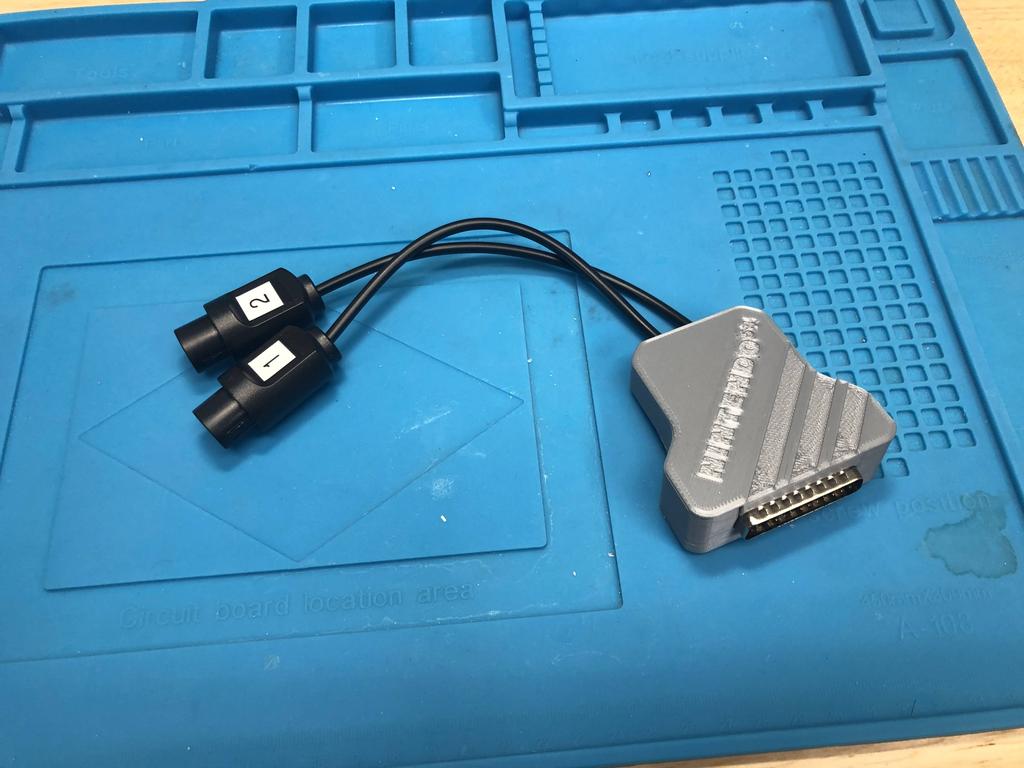
Done!
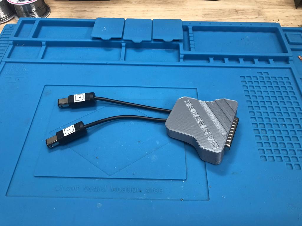
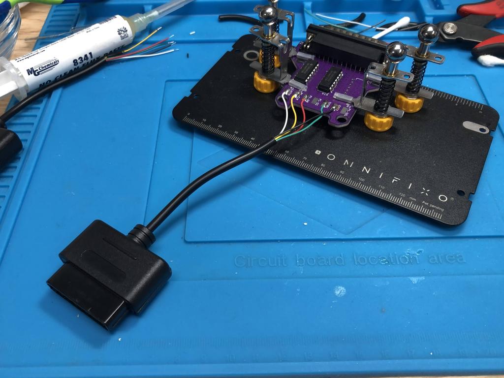
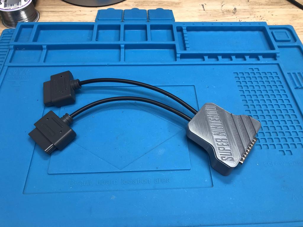
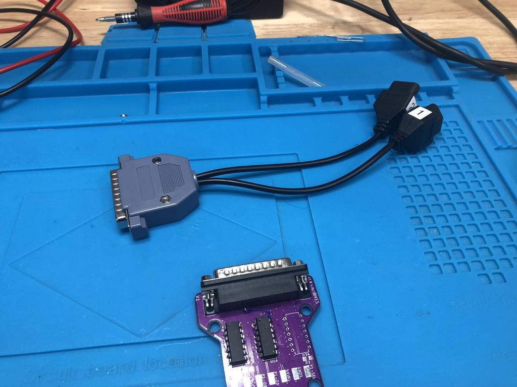
Here it is, hooked up to the receiver:
PSX/PS2 #
The PSX/PS2 adapter is also straightforward to build.
Parts:
- PCB
- 3D-printed shell
- DB25 connector (male, 90 degrees)
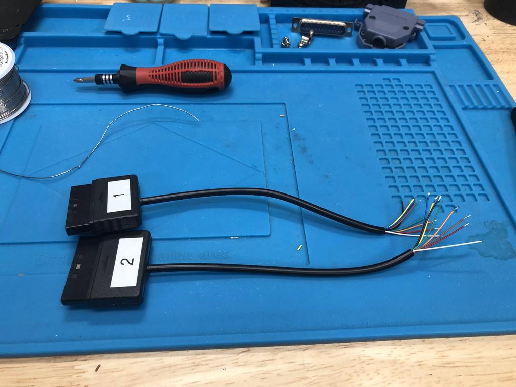
- PSX/PS2 extension cables (1 or 2)
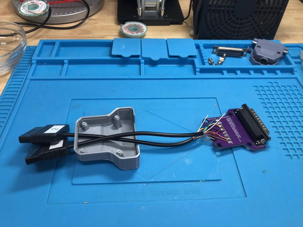
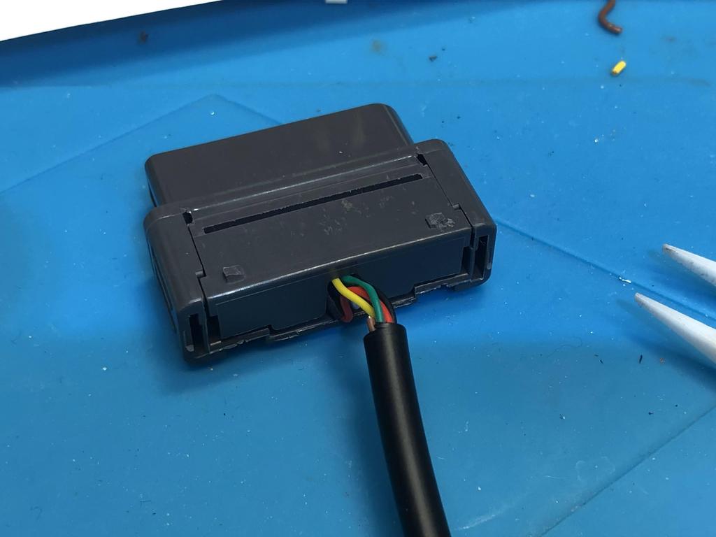
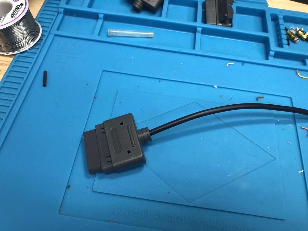
First, I undid my existing adapter. If starting from scratch, you’d want to cut and strip the ends of the extension cables, and tin each end:
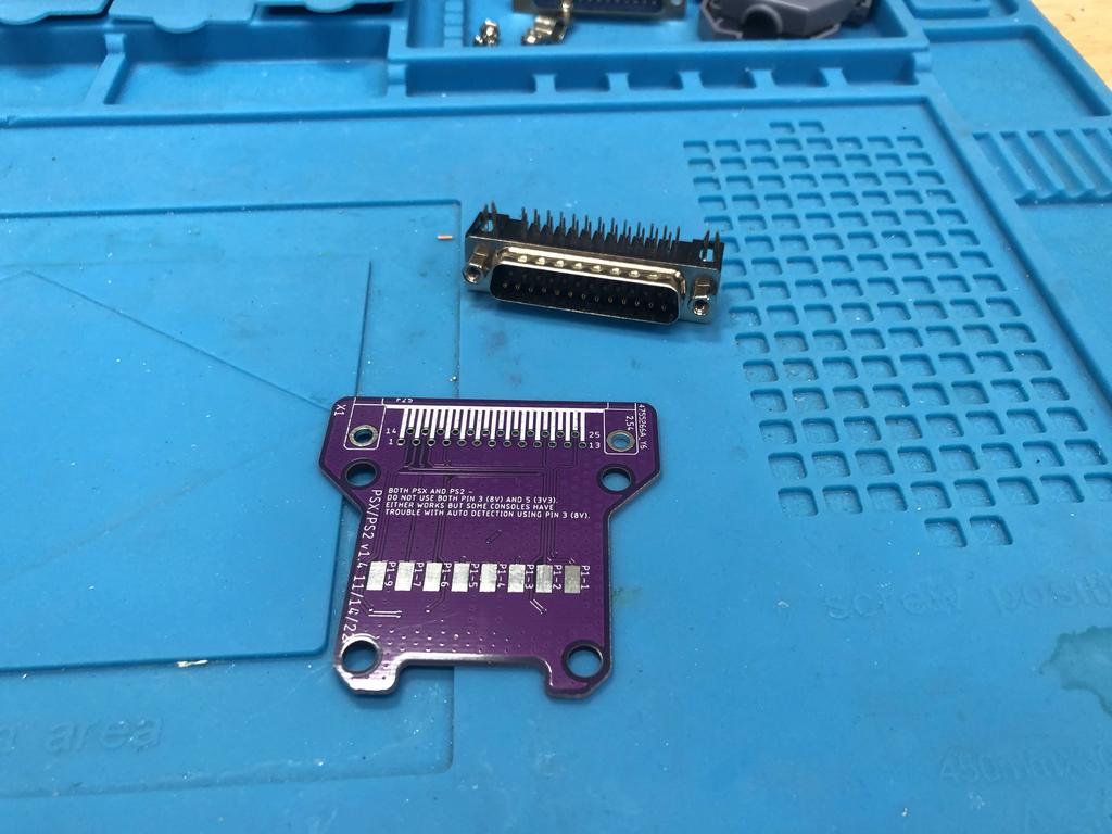
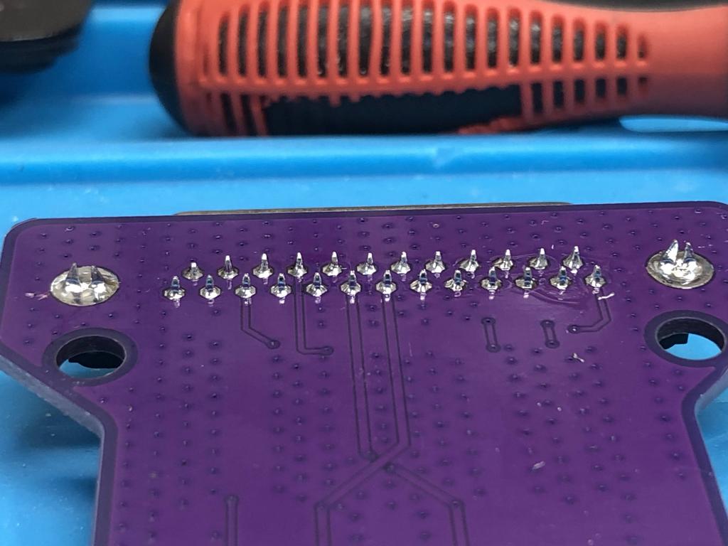
Next, I soldered the DB25 connector to the PCB:
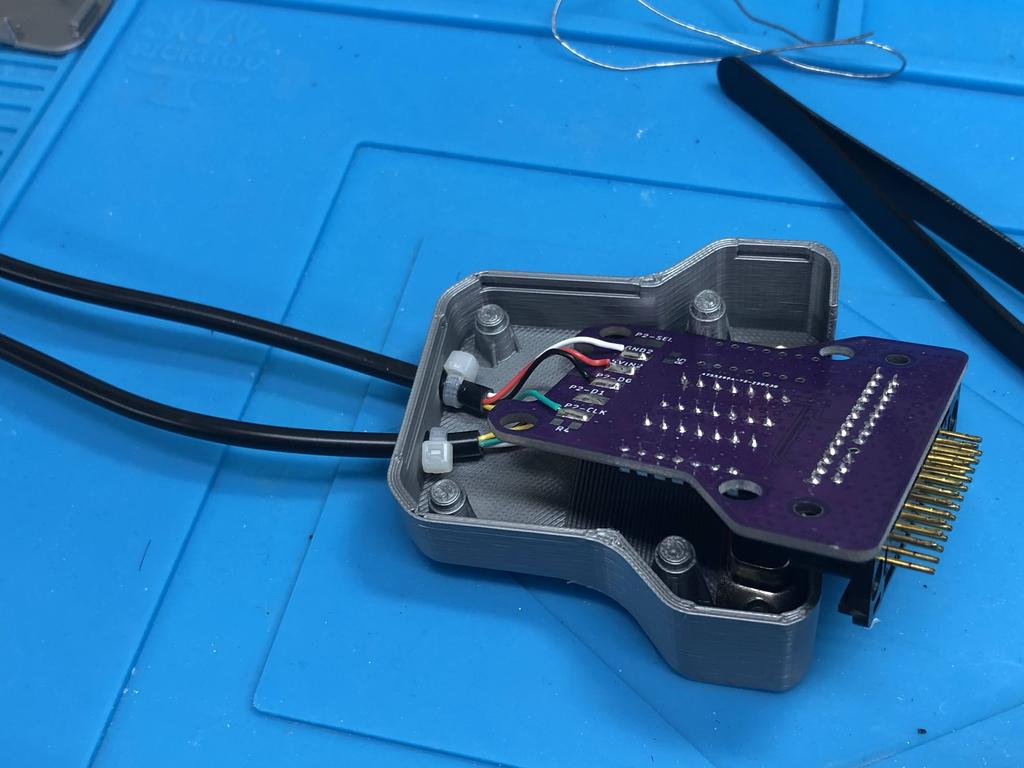
I threaded the cables through the bottom shell:
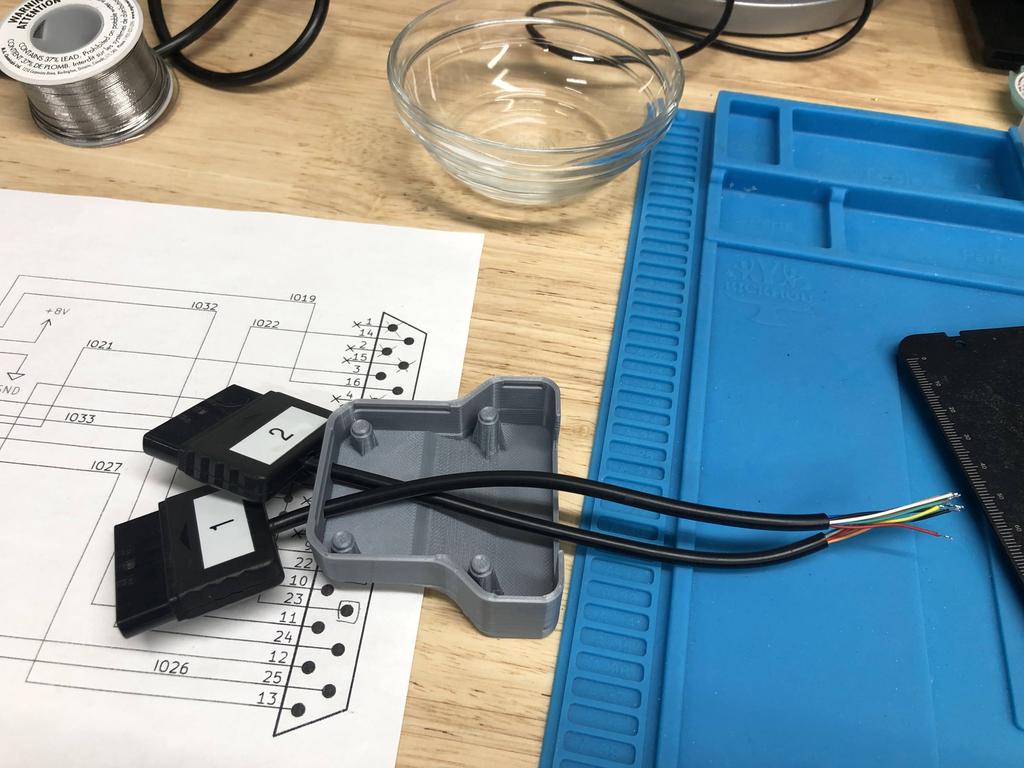
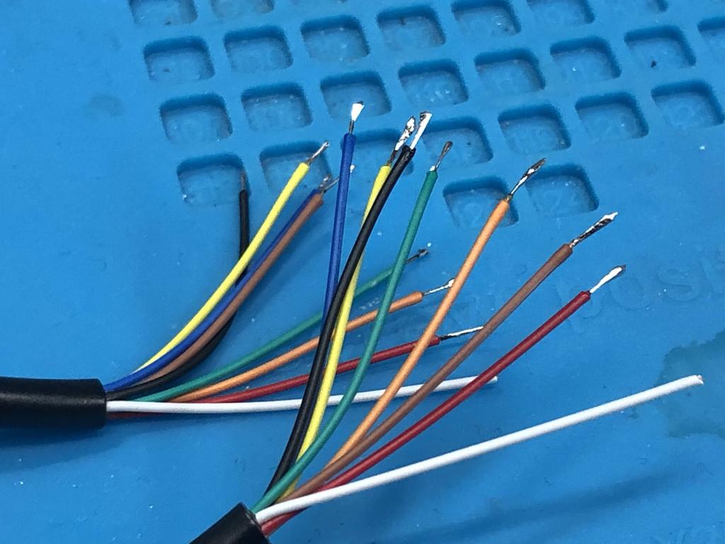
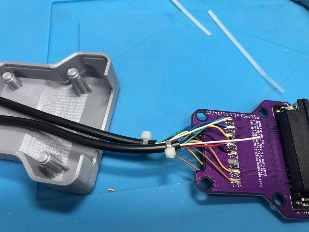
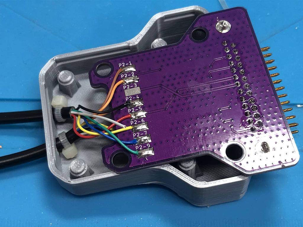
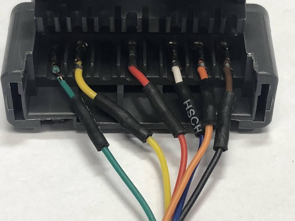
Now it was time to wire the cables to the PCB. I referred to the schematic I had printed before, where I had identified which color wire maps to which of the controller 9 pins:
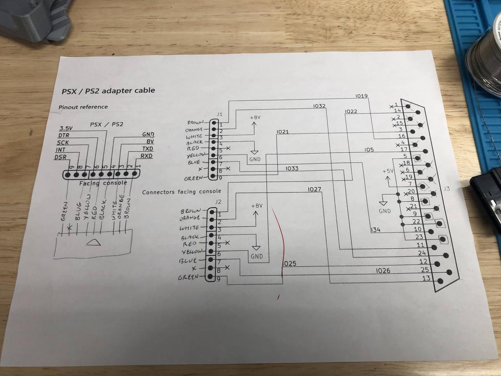
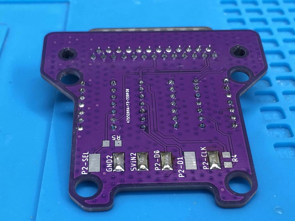
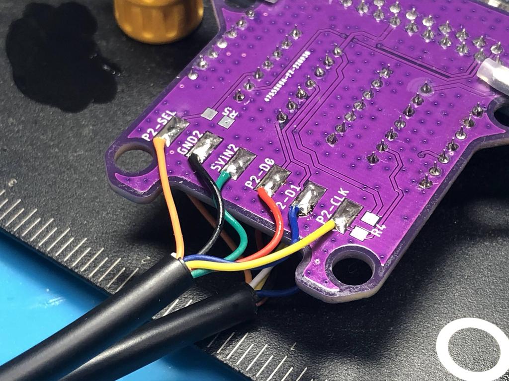
The PCB has all the player 1 pads on one side, and player 2 pads on the other side. I soldered the player 1 wires to each pad:
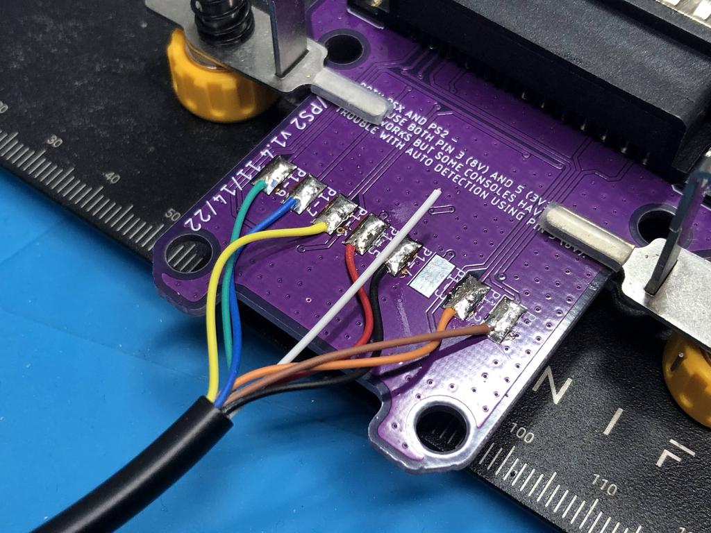
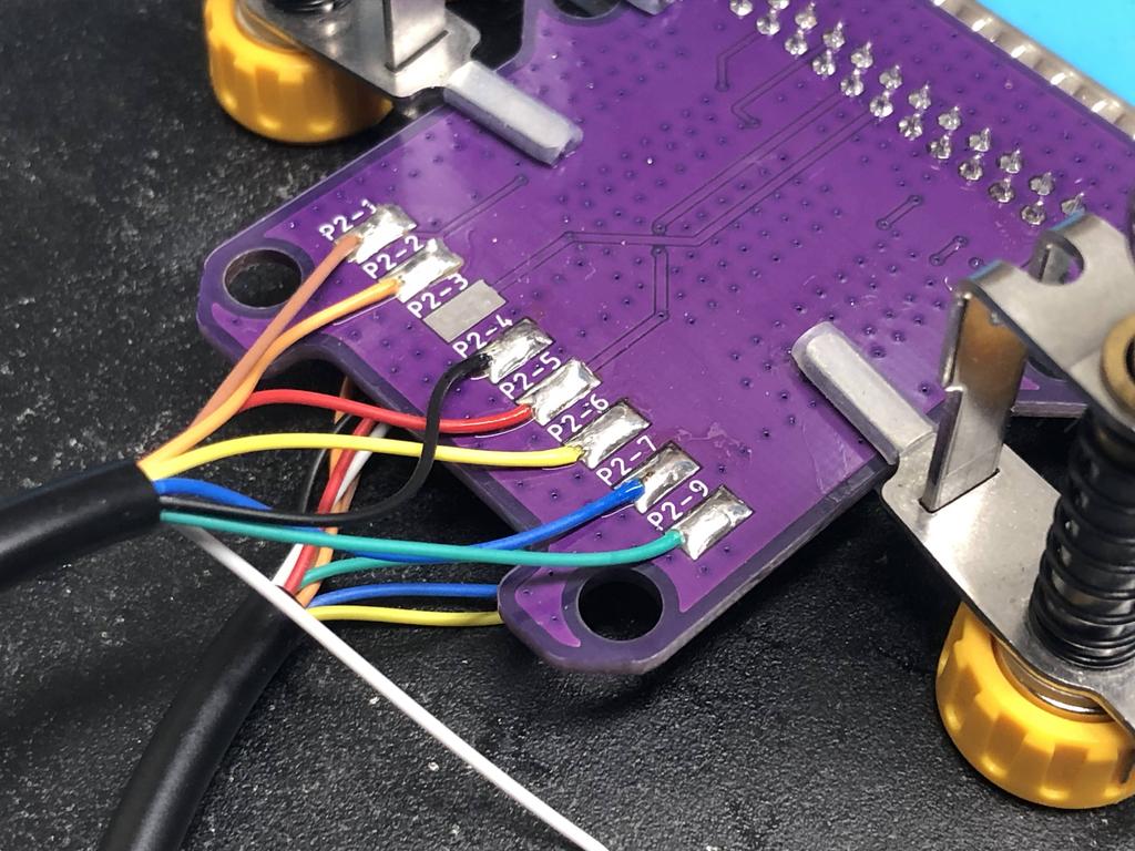
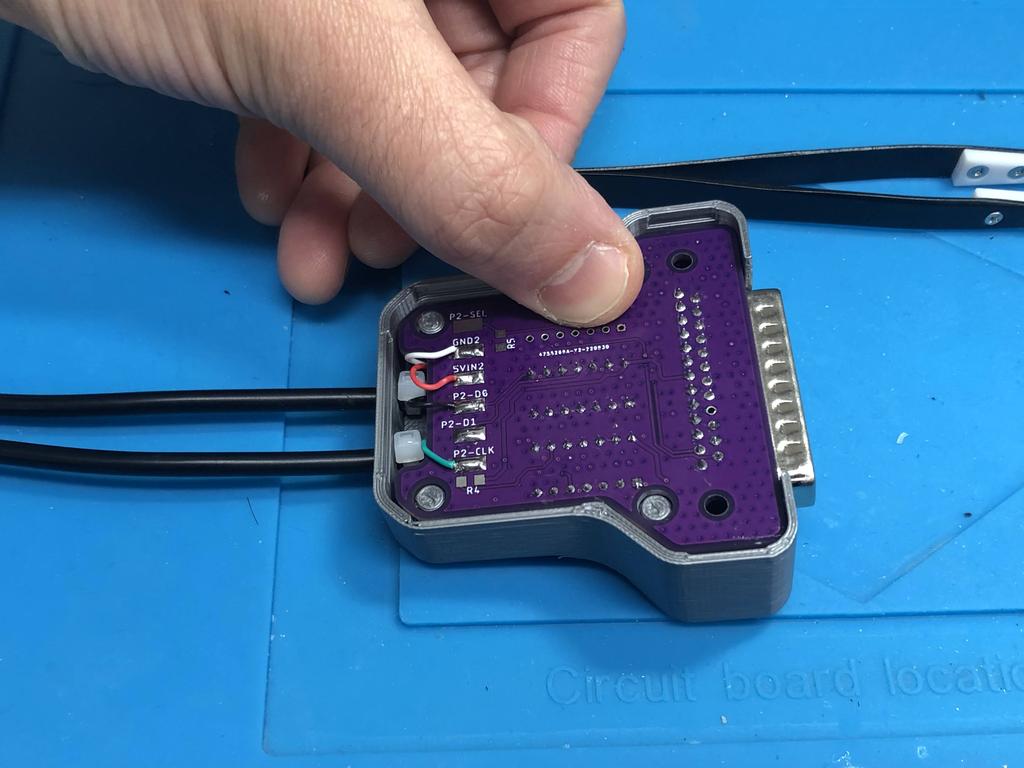
Then flipped the PCB and soldered the player 2 wires:
Note that on both sides, I did not solder anything to pads P1-3 and P2-3. This is because Pin 3 is 8V and Pin 5 is 3V3, and you should only solder one of these, not both for BlueRetro to work properly. I chose to solder to pin 5, and left the white wire (pin 3) disconnected.
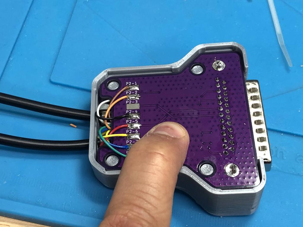
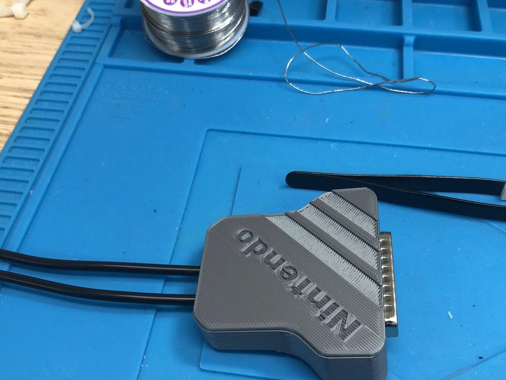
With wiring done, it was time to close things up:
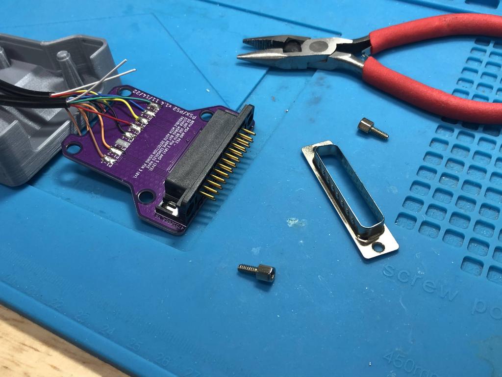
I removed the screw posts. Note that the metal face plate should be kept on the DB25 connector, unlike in this pic:
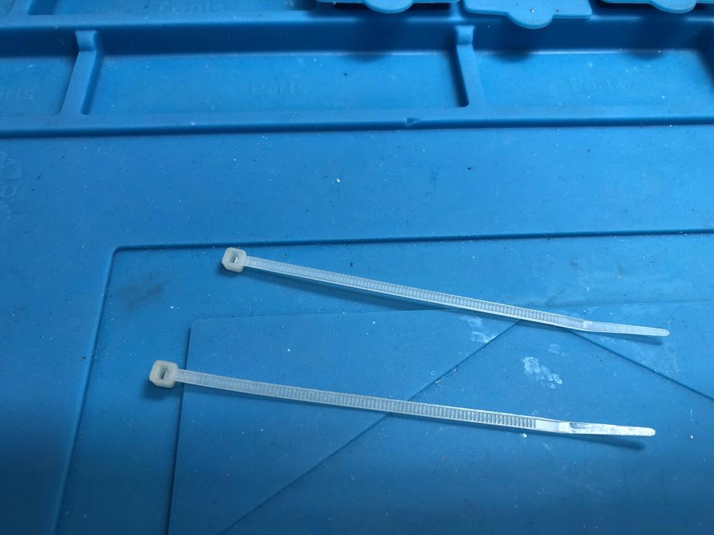
I used zip ties to create strain reliefs:
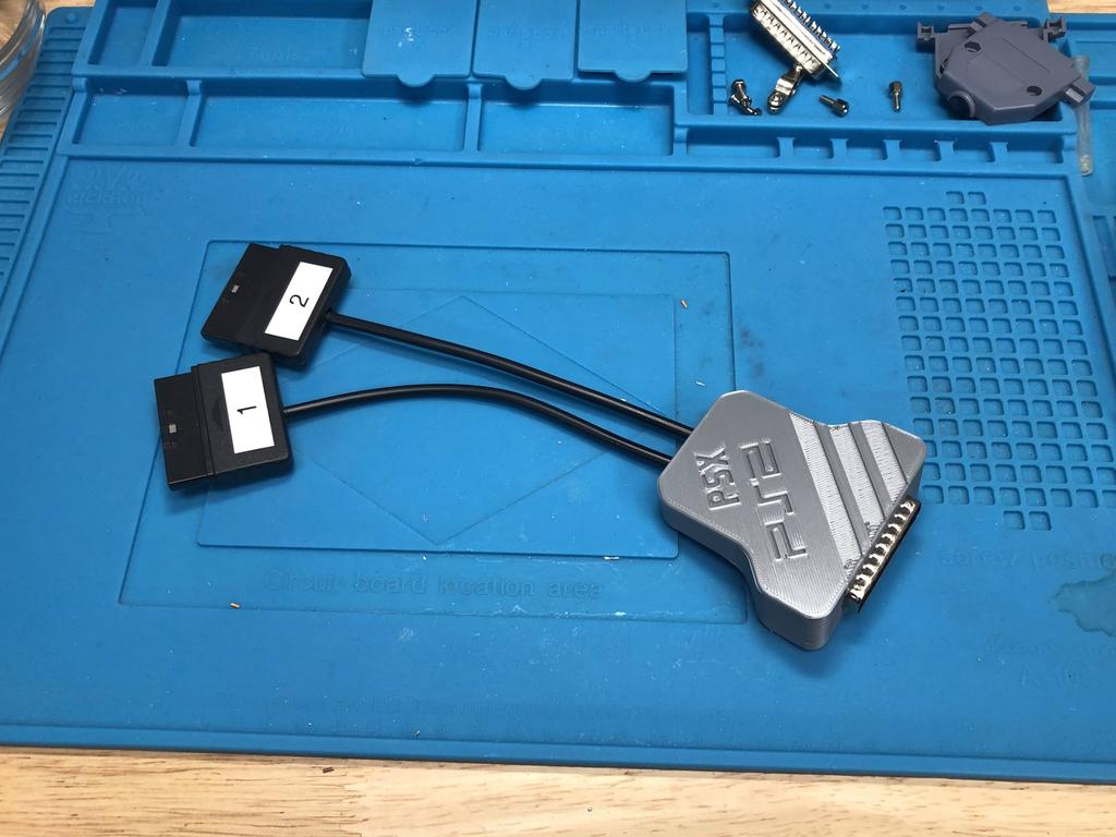
Then closed everything up:
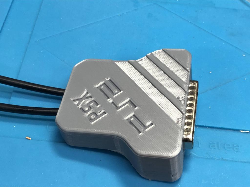
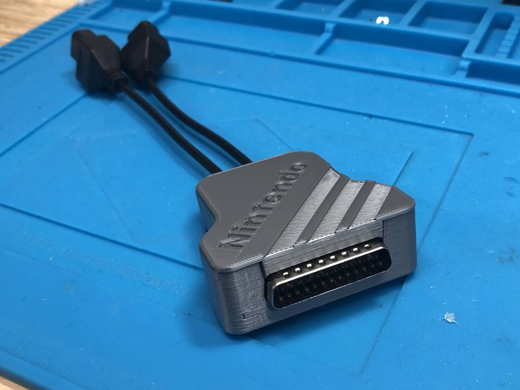
Done!
SNES - 2 Player #
The first time I made the SNES adapter, it only supported 2 players. I also didn’t have my 3D printer yet, so this build was a little bare-boned.
Parts:
- PCB
- DB25 connector (male, 90 degrees)
- SNES extension cables (x2)
- 74AHCT125N quad level-shifters (x2 for 2-player)
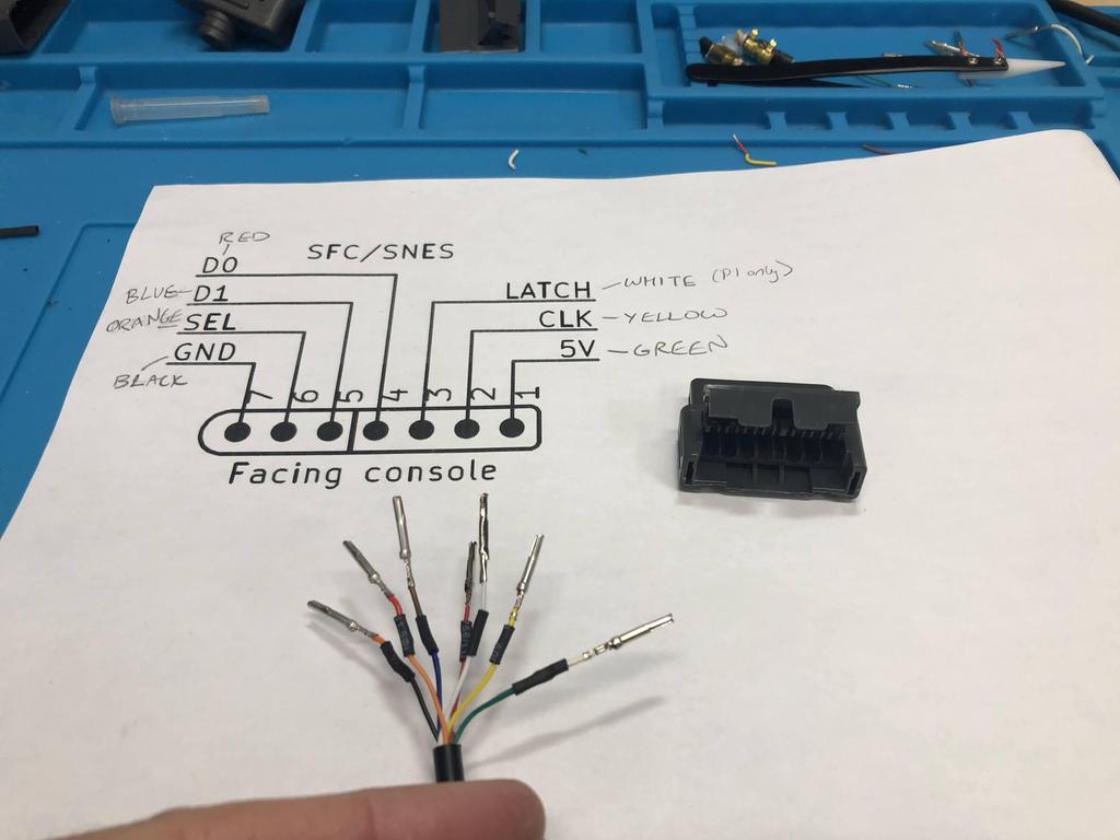
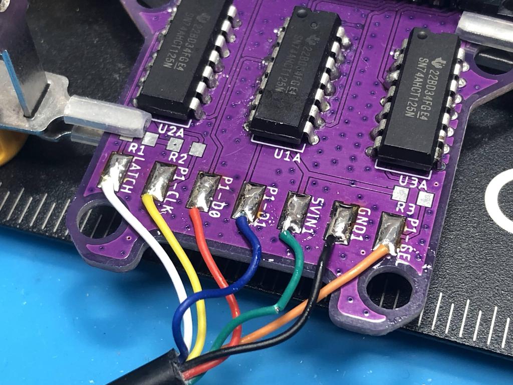
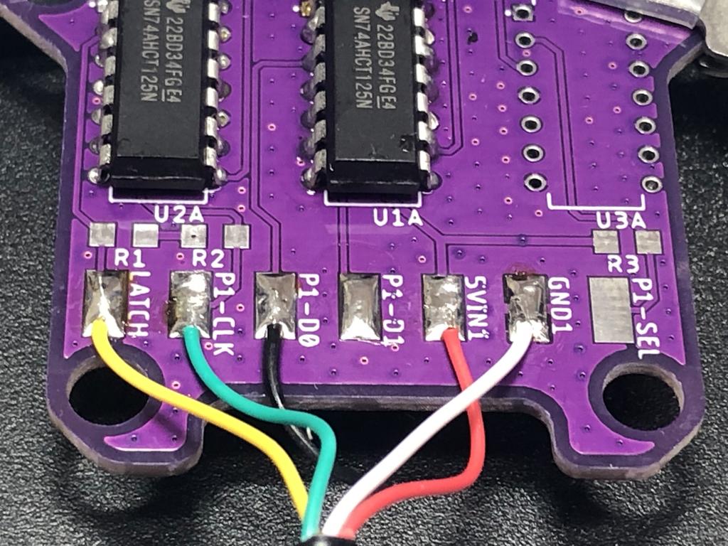
Looking at the schematic, it initially looks like we need to wire up 7 wires for the first controller, and 6 for the second, because the LATCH (pin 3) is not required for player 2:
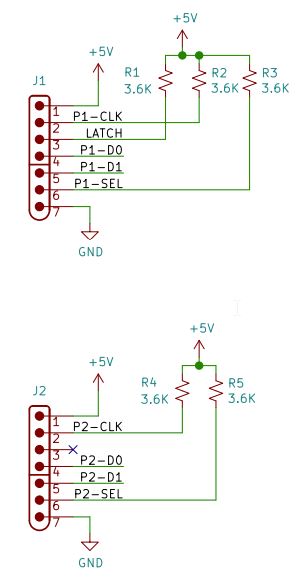
However, the rest of the schematic outlines connections in blue that only need to be made if you want multitap support:
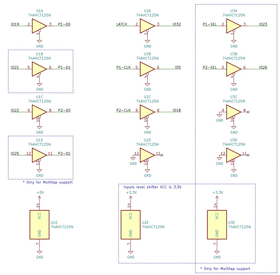
In this build, we’re only interested in supporting 2 players, so we don’t need to connect P1-SEL, P2-SEL, P1-D1, and P2-D1. We also don’t need a third level-shifter. So that means we only need 5 wires for the first controller, and 4 for the second. In fact, it turns out that SNES controllers (and extension cables) only have 5 wires in them. The other pins are left unpopulated, and were there for third-party adapters, such as the light gun and the multitap.
Alright, on with the build!
First, I cut, stripped, and tinned the extension cables:
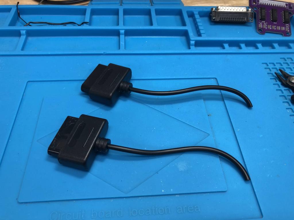
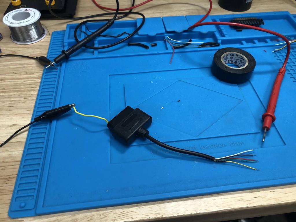
Using my multimeter, I identified the mapping of each pin to each wire color. You can see how there are only 5 wires:
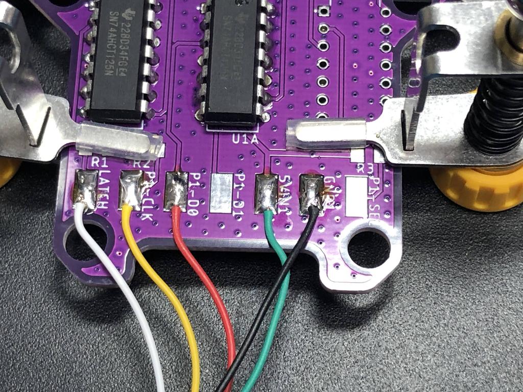
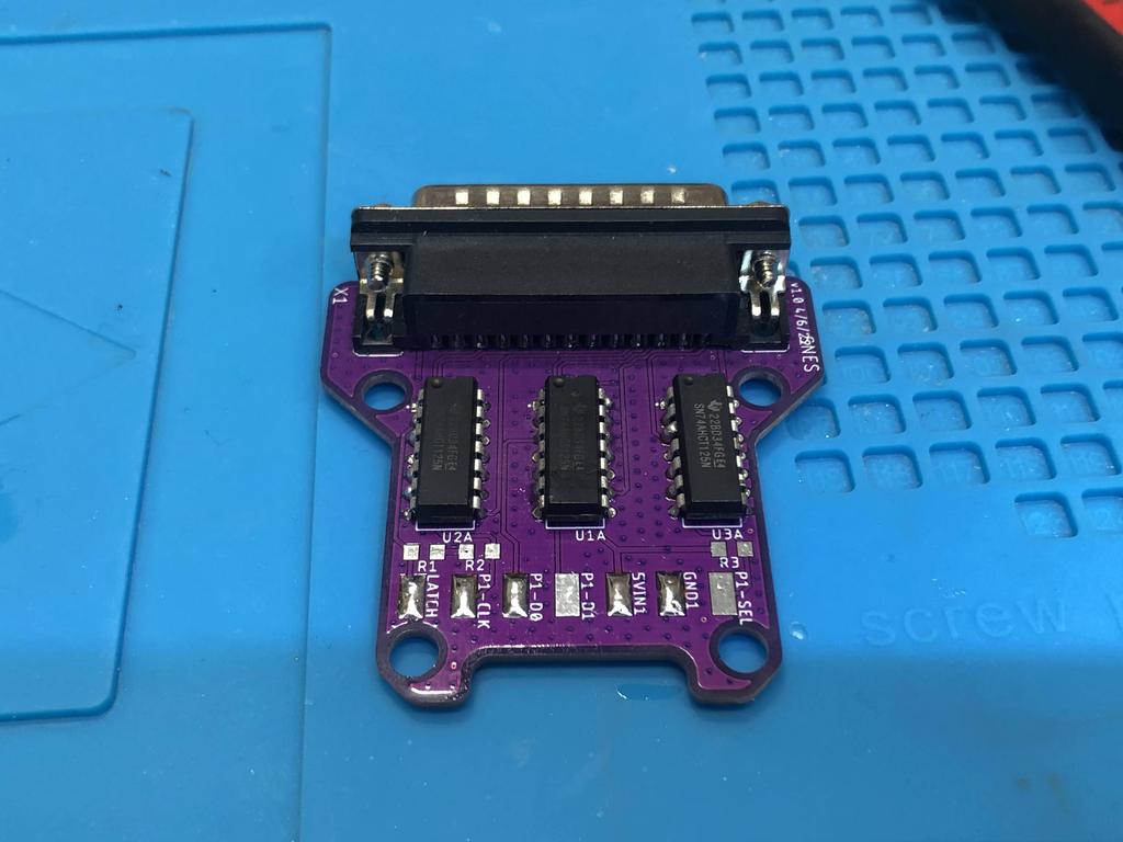
Next, I soldered in the 2 level-shifters to the PCB:
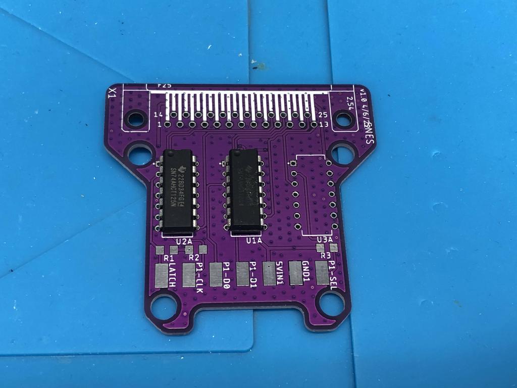
Then I soldered the DB25 connector:
If I had the 3D-printed shells, I would normally have inserted the controller cables into them here. But I didn’t, so I proceeded to solder each one to the PCB:
Player 1 side:
Player 2 side:
Note that the player 2’s latch wire (white) is not soldered to the board:
In retrospect, I realize that one thing I forgot to do is to “connect IO21 & IO25 to GND”, as per the assembly instructions, since we’re not enabling multitap support. Concretely, this means I should have soldered the P1-D1 and P2-D1 pads to one of the GND pads.
As I didn’t have my 3D printer yet, I used a couple of zip ties to secure the wires:
And with that, I was done. In the next section, I convert this one to support 4-player multitap mode, and add a proper shell.
SNES - Multitap #
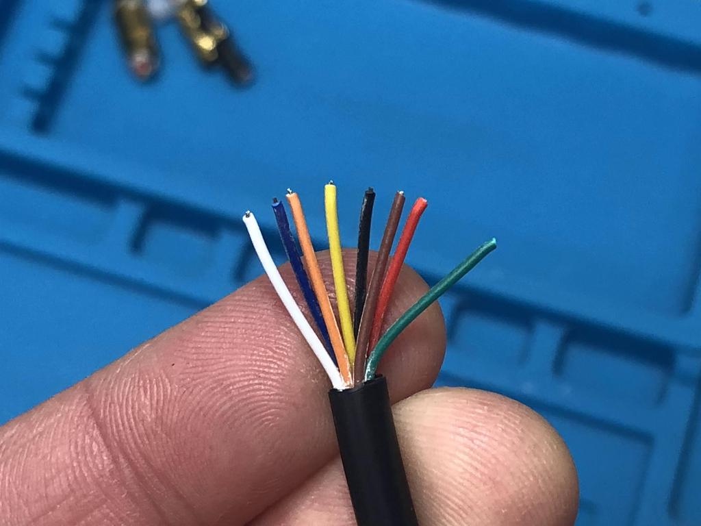
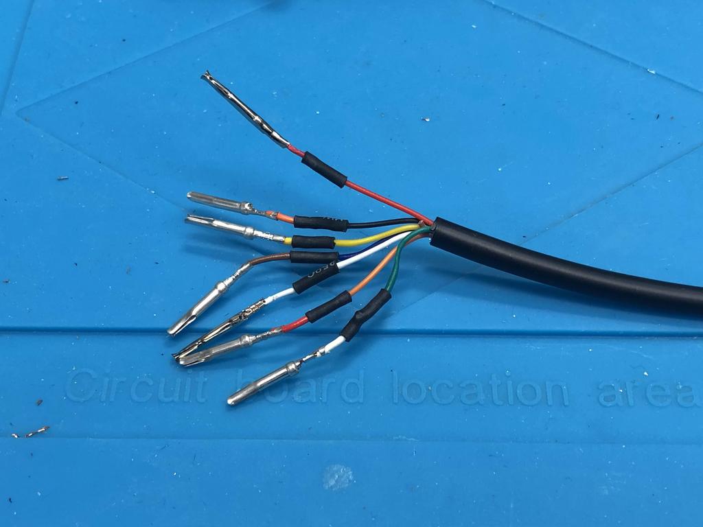
Making a multitap BlueRetro adapter is a bit more work because SNES controllers/extensions only have 5 wires in them, but we need 7 for the first player, and 6 for the second. This means we need a 7 wire cable for each controller, as well as 3 extra pin ends to insert into the SNES controller ends. All of this will be made clearer below.
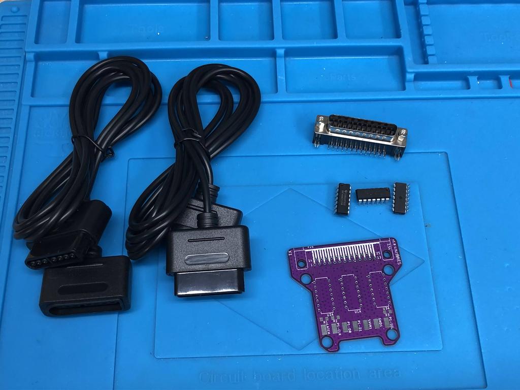
Parts:
- PCB
- DB25 connector (male, 90 degrees)
- 7 wire cable (can use a PSX/PS2 controller cable)
- SNES controllers/extensions (3x)
- 74AHCT125N quad level-shifters (x3 for 4-player)
First, I took apart the 2-player version I had made, and soldered in the third level-shifter:
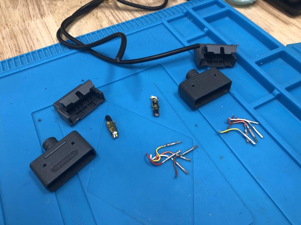
I had bought a lot of Super Famicom controllers on eBay with the intention of converting four of them into Bluetooth controllers using 8BitDo mod kits. As I didn’t need the cables, I decided to use the controller ends from two of them:
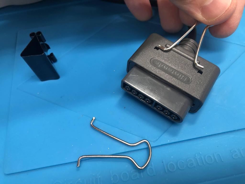
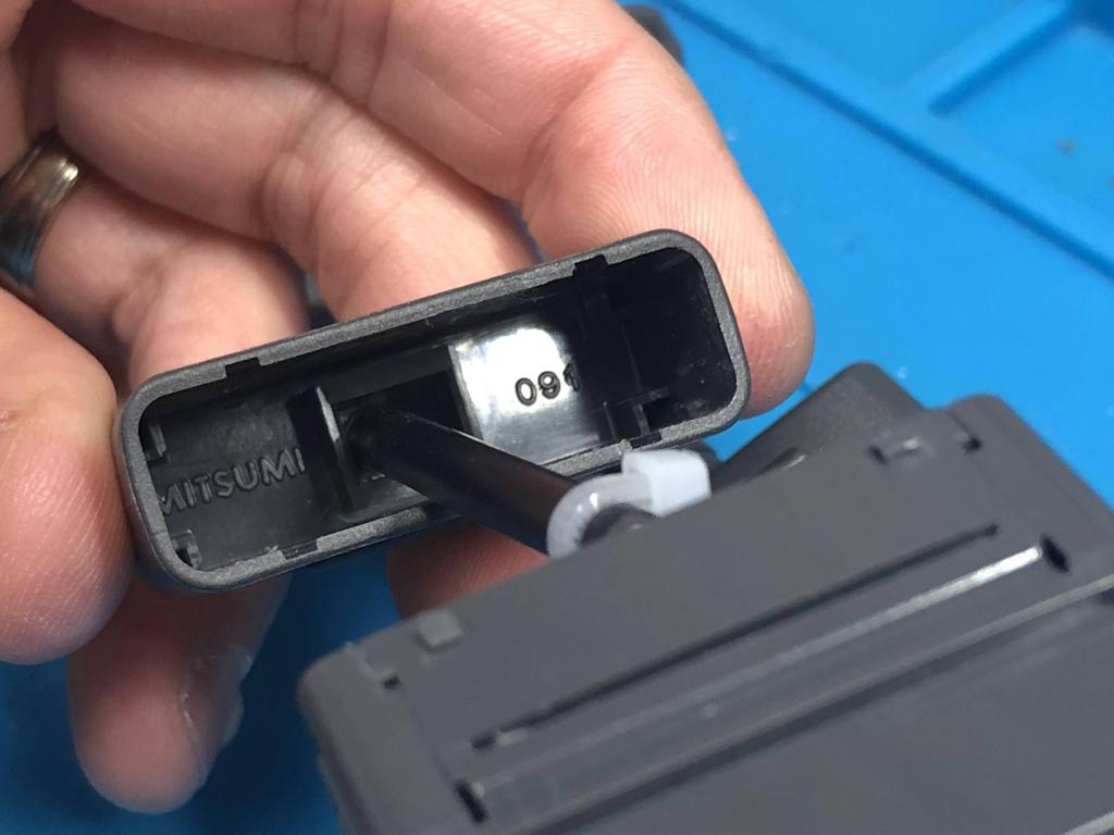
It turns out it’s really heard to open up the controller end. I made myself a little tool using one of those paper clips:
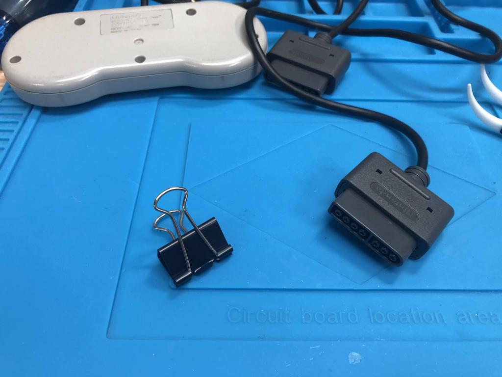
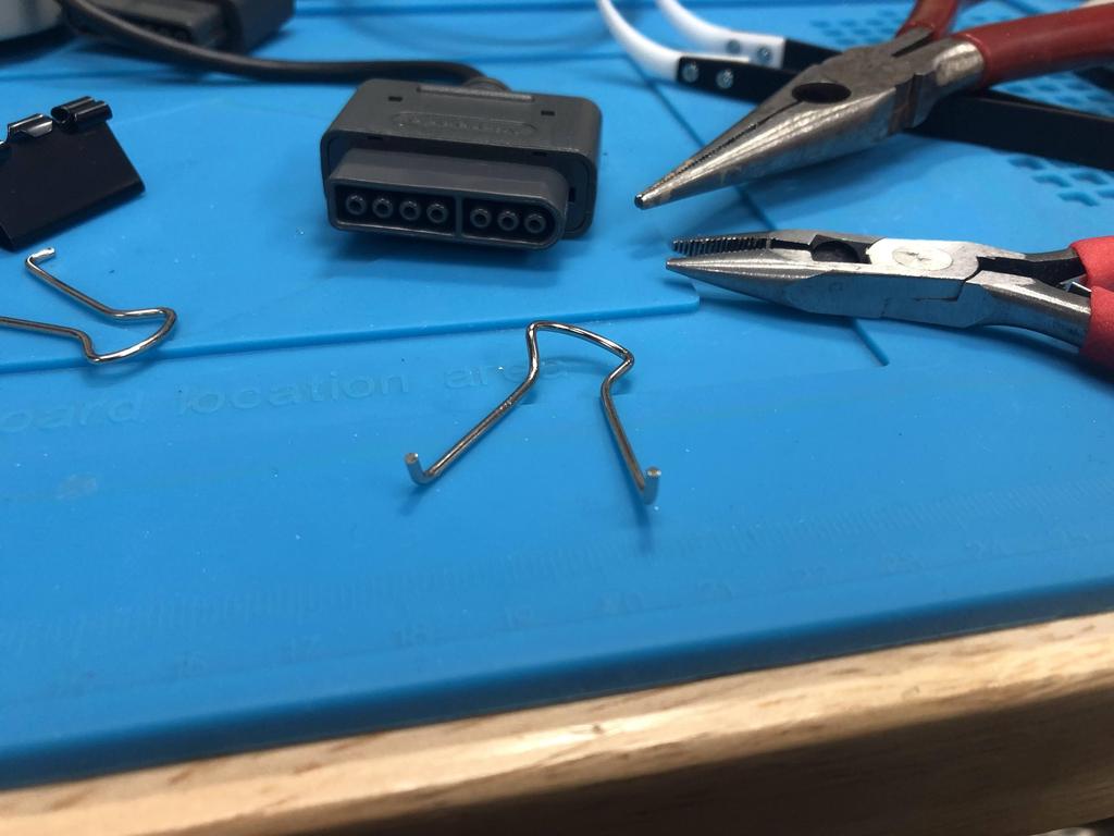
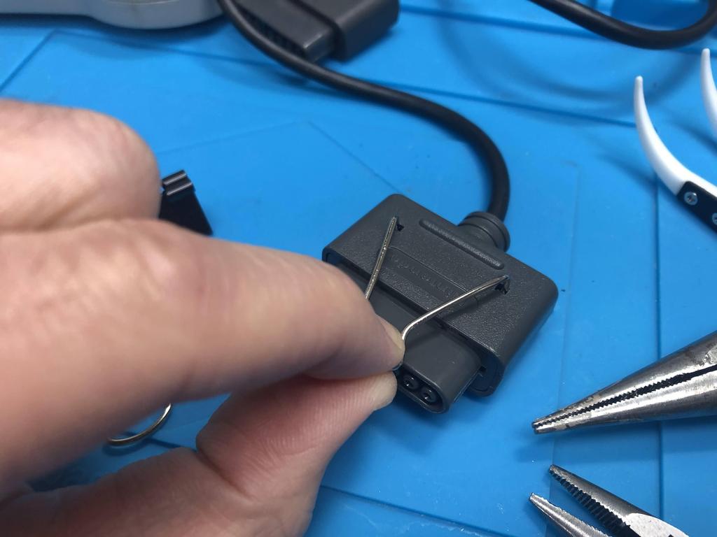
This was still really hard, so I ended up using a blade to cut off the two plastic pegs on the other side. Once cut, and using my tool, I was finally able to pry off the end:
Lifting up the plastic “door”, we can see how SNES controllers only have 5 wires in them, leaving 2 pins empty:
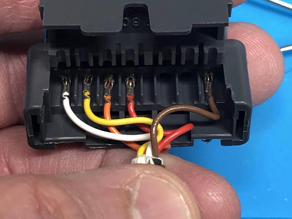
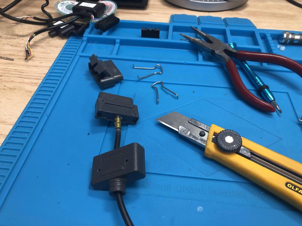
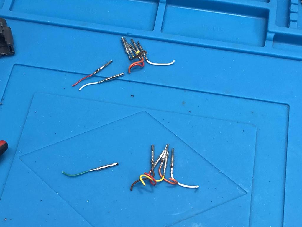
Our goal is to cut off all those metal pins and resolder them to a 7-cable wire. But for that, I needed 3 more pins, which I got from one of the extension cables:
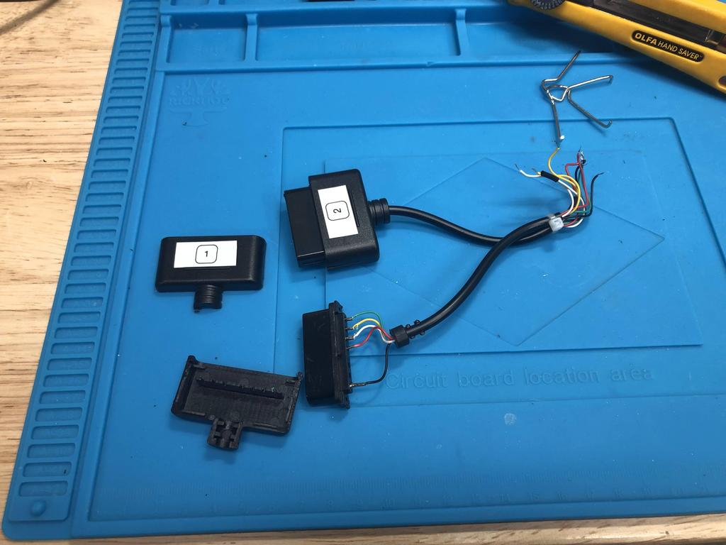
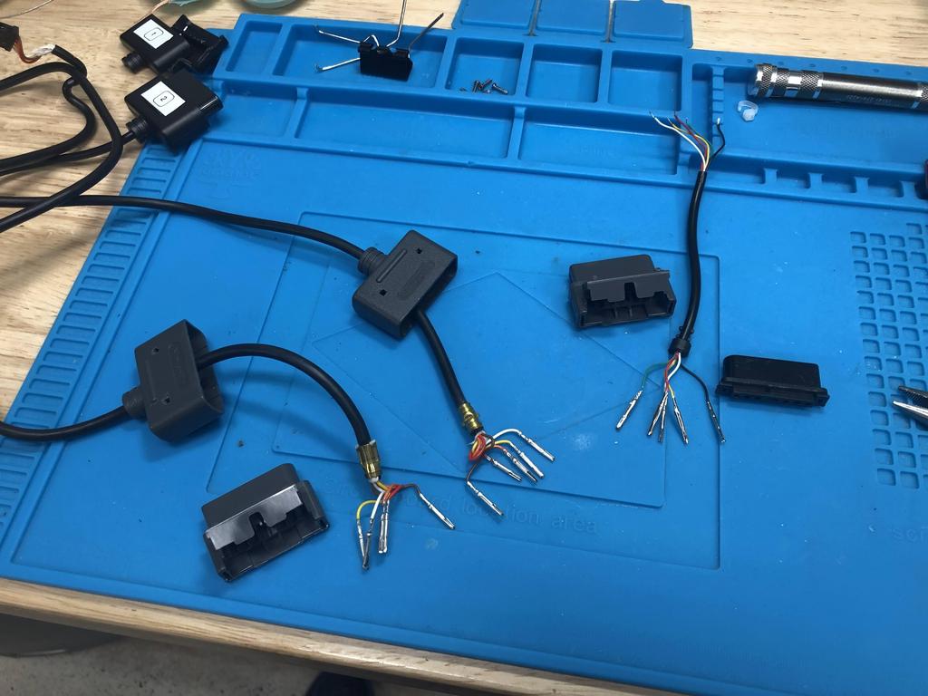
I cut off all the ends, keeping a little bit of the wire:
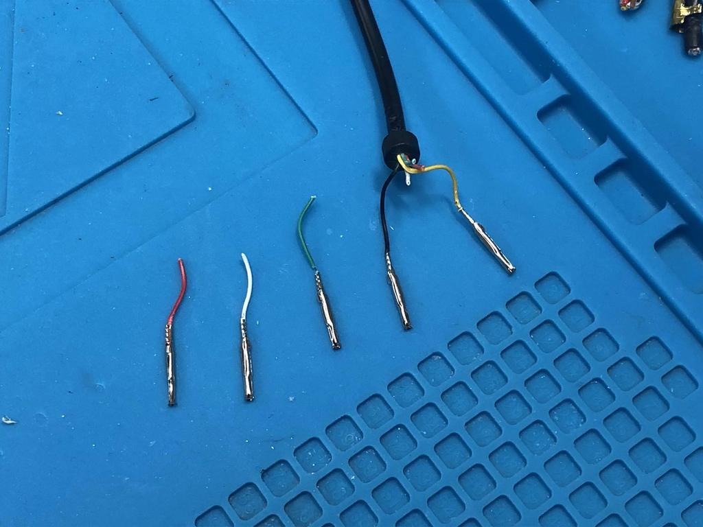
7 wires for player 1 (top), and 6 for player 2 (bottom):
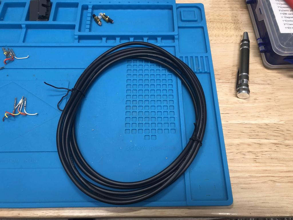
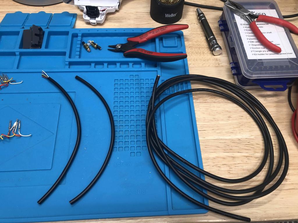
I used an 8-wire cable I had lying around. Another alternative is to use a PSX/PS2 controller cable, which has 7 wires in it:
I soldered the controller end pins to each cable:
I then reinserted the pins back into the controller ends, making sure they matched up with the schematic.
I slid the cap back on, but left it loose until the very end. It was a pain to remove, so I wanted to make sure everything worked first:
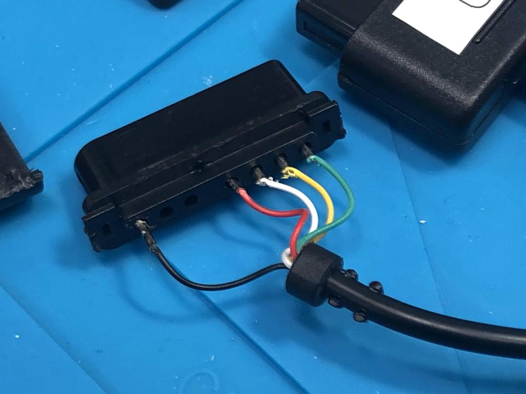
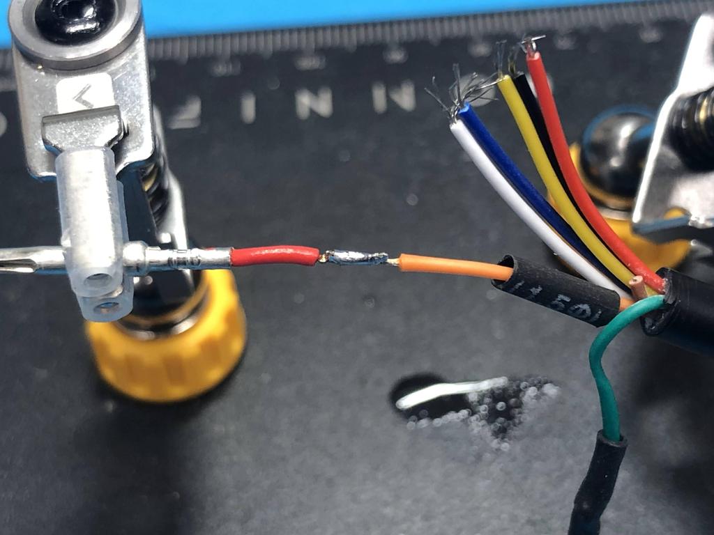
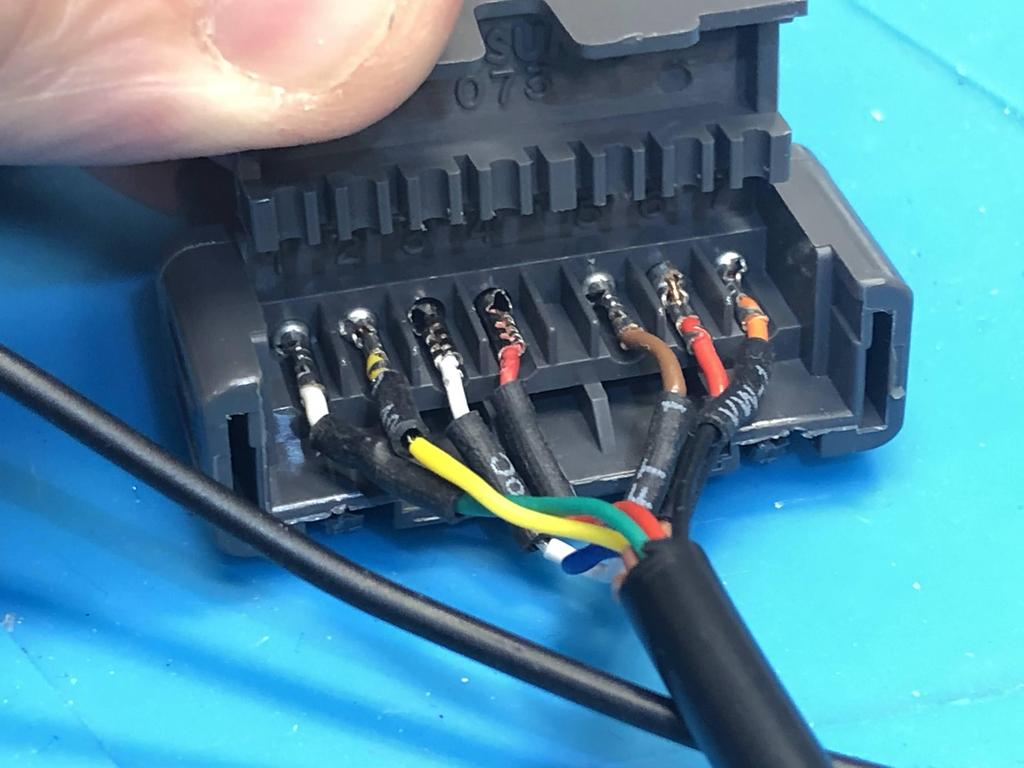
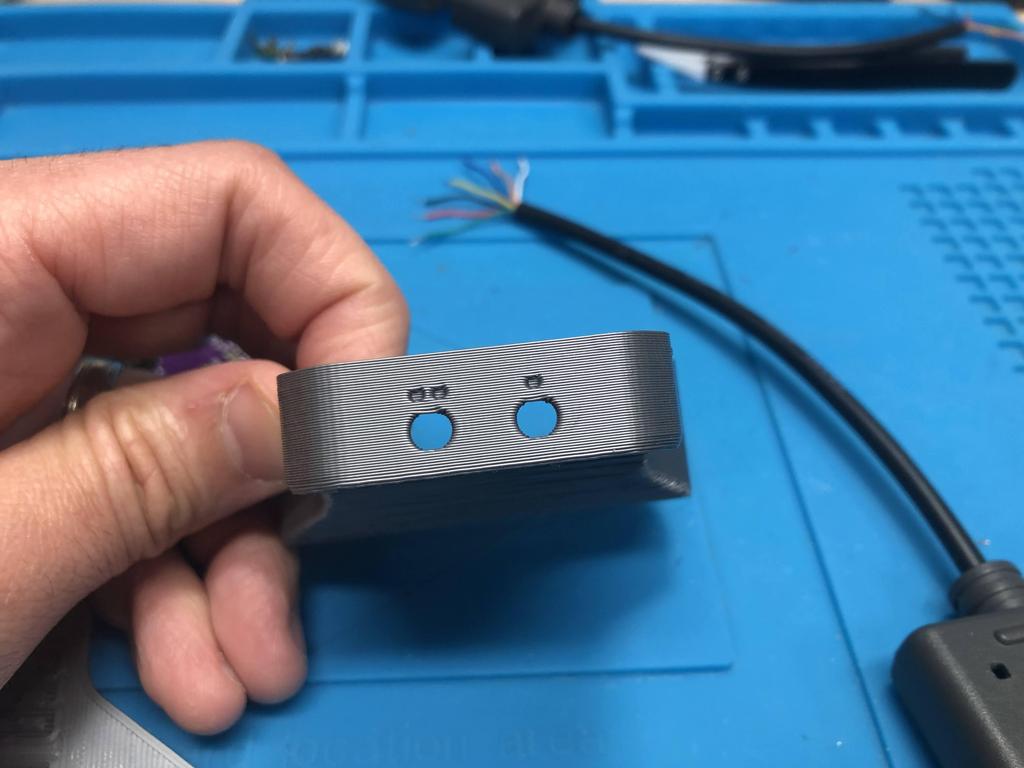
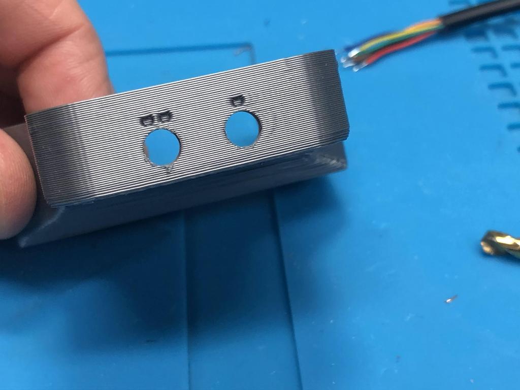
I inserted the player 2 cable wires, which is missing the LATCH wire (third from left):
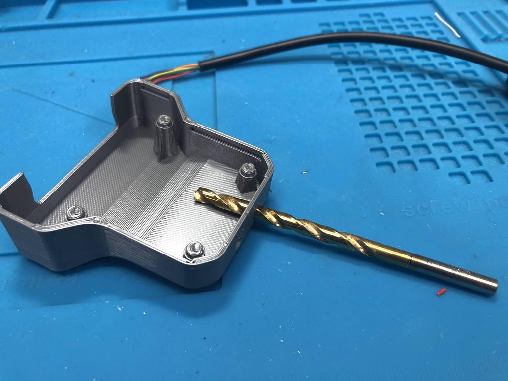
These cables were pretty thick, so to insert them into the bottom shell, I needed to make the hole bigger by manually twisting a drill bit through the holes:
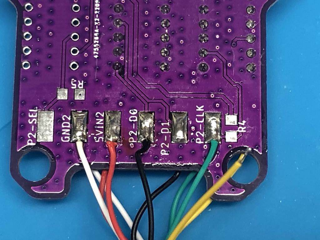
I soldered the player 1 wires to one side of the PCB:
Then player 2:
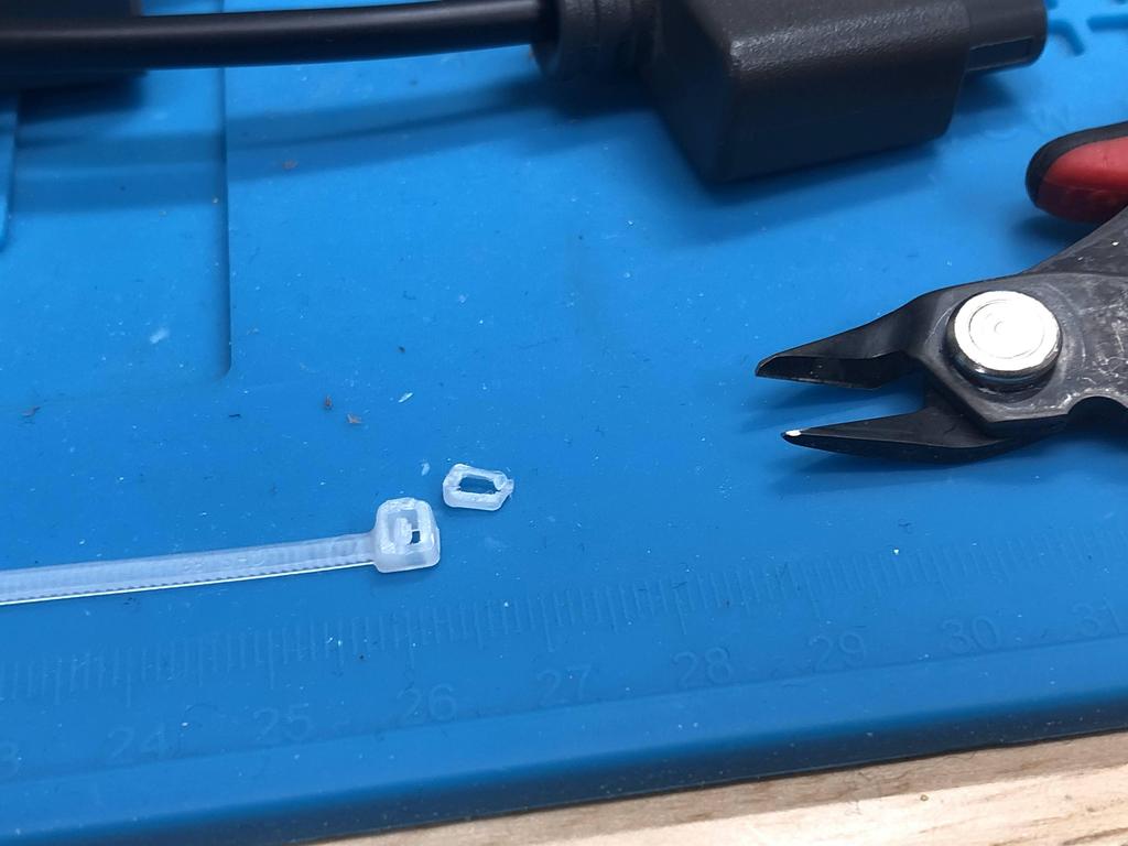
To close things up, I needed to add some kind of strain relief to the cable end:
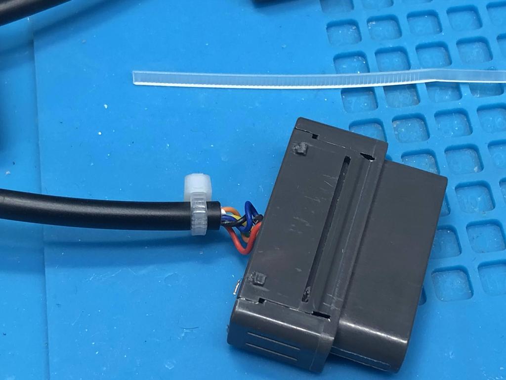
This didn’t quite fit in the little cavity inside the cable end cover, so I snipped a little off the zip tie, and that worked:
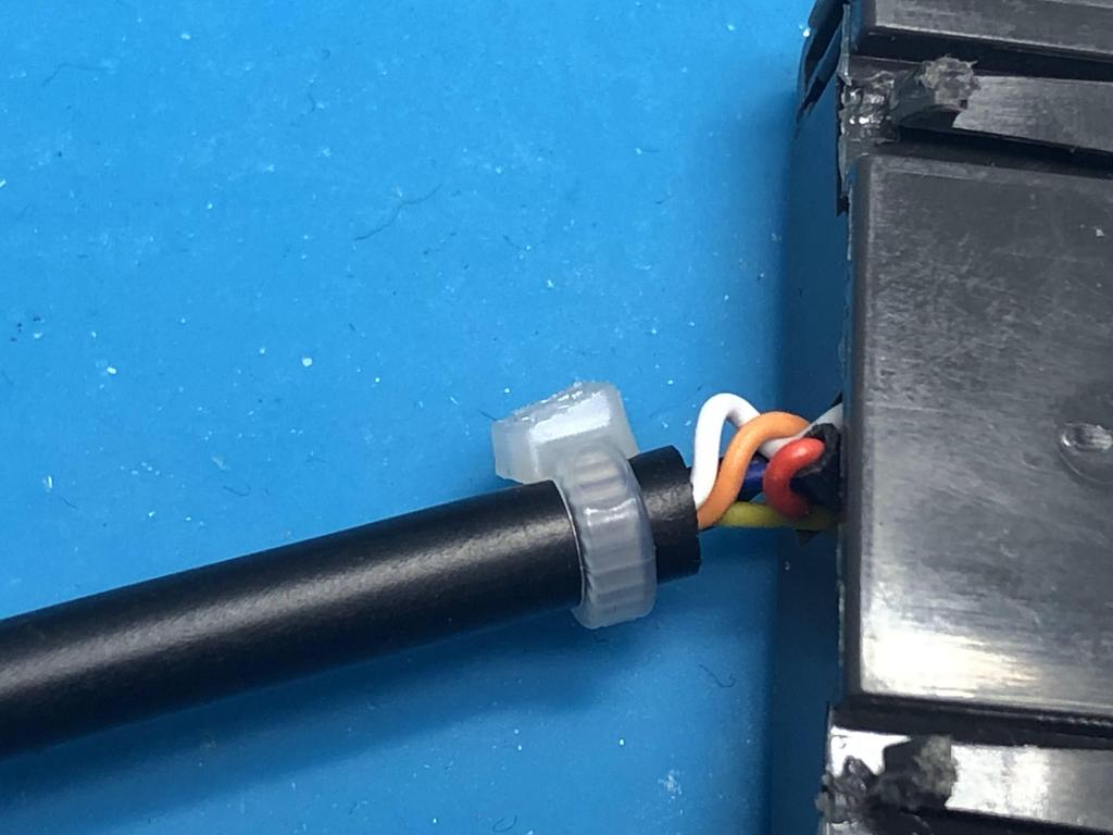
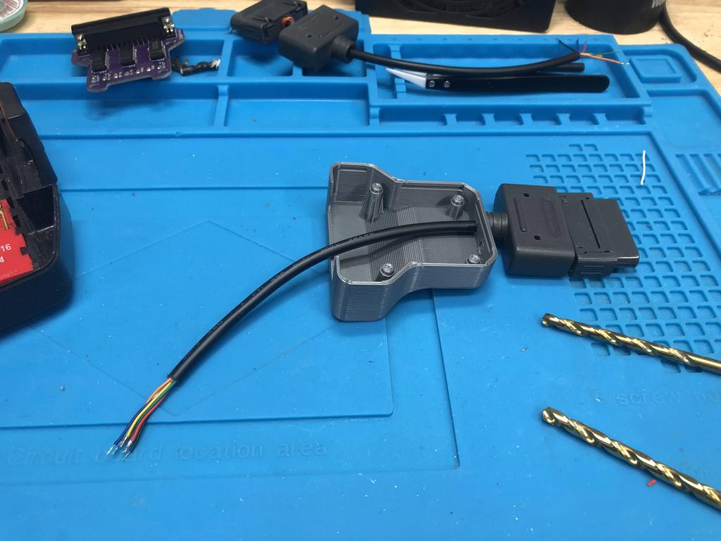
I also put the usual strain reliefs on the other end of the cables so that they stay inside the shell:
And closed everything up:
Done!
NES #
The last build I’m covering is the NES one. This one is simpler that the SNES one, but I cover it afterwards because I ended up using a SNES PCB instead of an NES one. The reason for this is that the NES and SNES controllers are very similar, as are the PCBs for both. Since JLPCB requires a minimum order of 5 PCBs, this also allowed me to save money and avoid printing 5 more for the NES.
Parts:
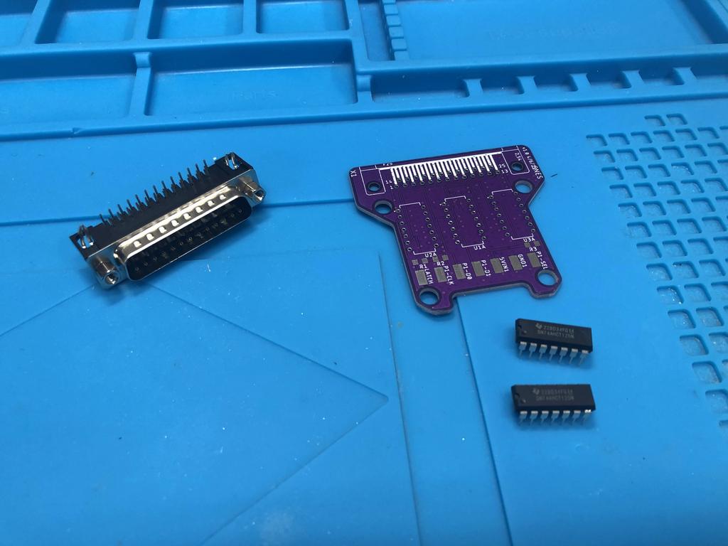
- PCB
- DB25 connector (male, 90 degrees)
- NES extension cables (x2)
- 74AHCT125N quad level-shifters (x2)
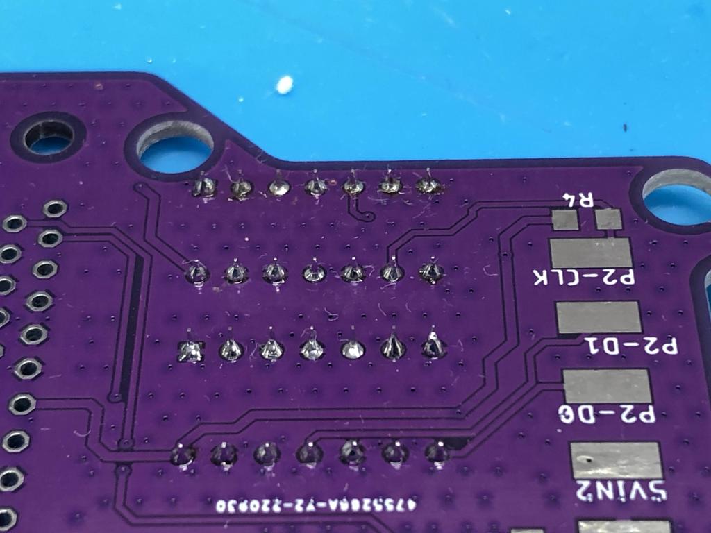
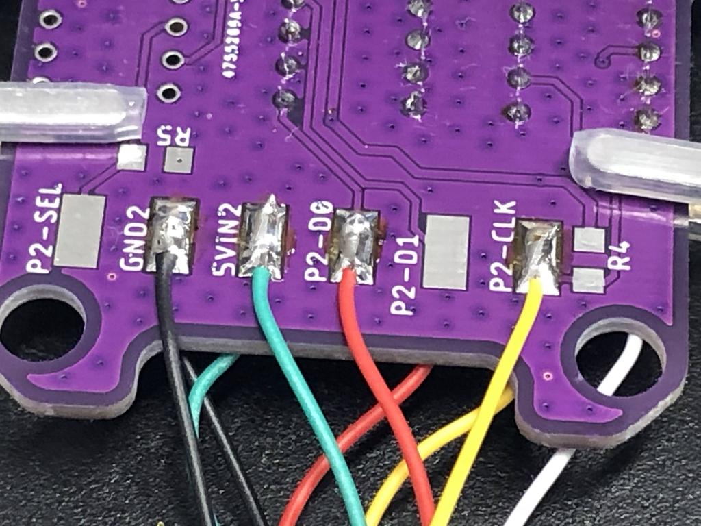
The first thing I did was compare the two PCBs online, and map out the differences:

Basically, the pads map this way:
| NES | SNES |
|---|---|
| P1-D0 | P1-D0 |
| P1-CUP | P1-CLK |
| OUT0 | LATCH |
| GND1 | GND1 |
| 5VIN1 | 5VIN1 |
| P2-D0 | P2-D0 |
| P2-CUP | P2-CLK |
| GND2 | GND2 |
| 5VIN2 | 5VIN2 |
The other important part is how the BlueRetro identifies that it’s the NES that’s connected, and not the SNES. The way it does this is by looking at pin 22 of the DB25 connector: if it’s tied to GND, then it’s a SNES, if it’s tied to 3V3, it’s an NES. The SNES PCB is designed to tie pin 22 to GND, so we need to address this.
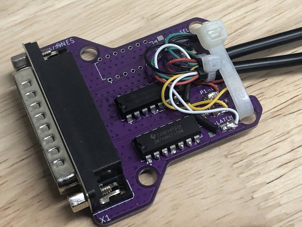
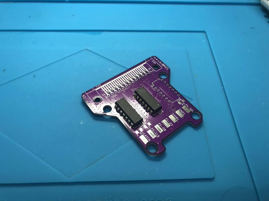
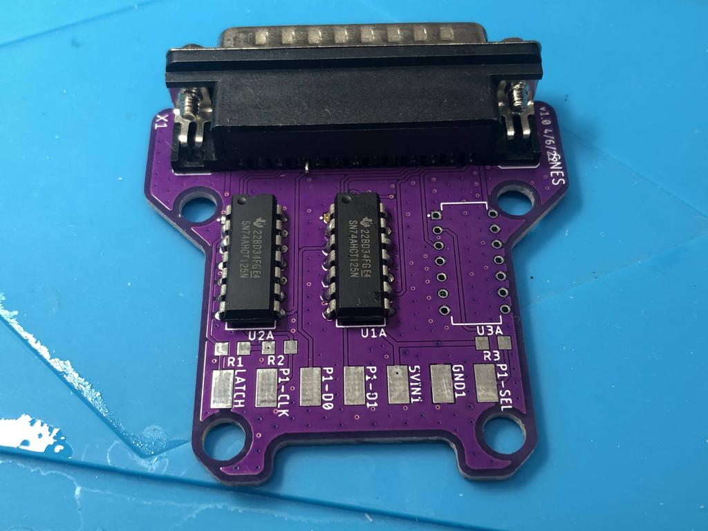
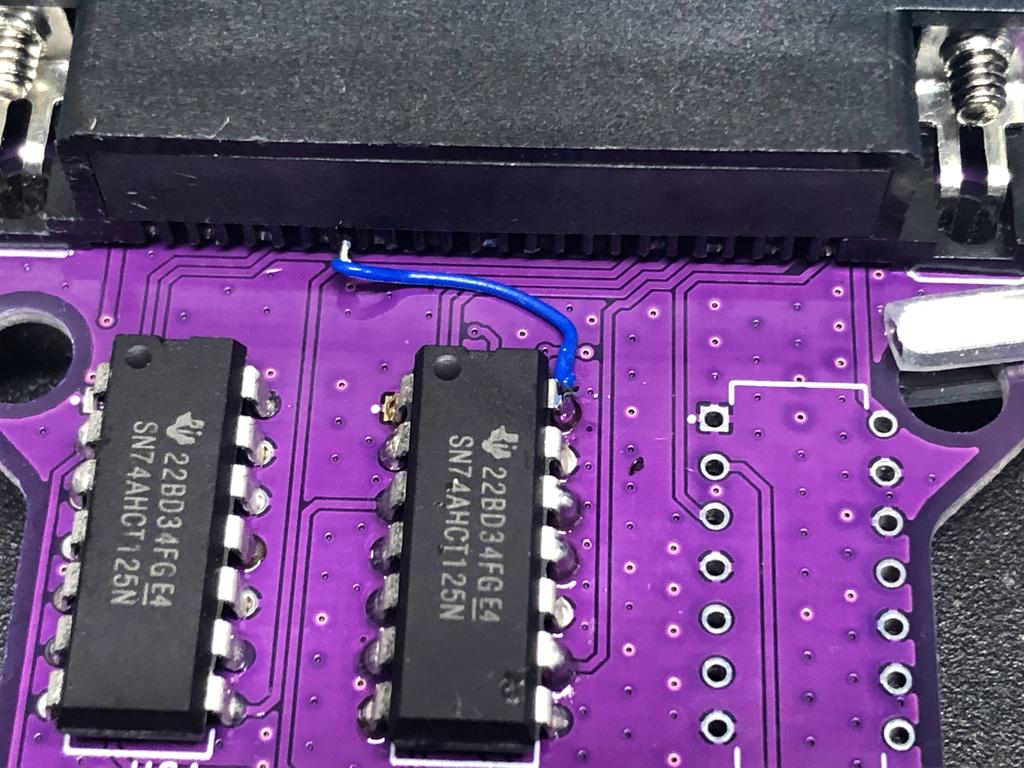
First, I soldered the two level-shifters to the PCB:
Now here is where we address pin 22 that needs to be tied to 3V3. What I did was bend pin 22 across this way:
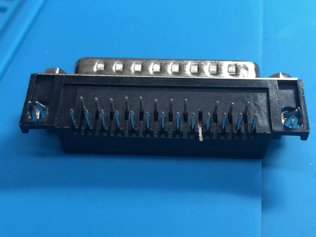
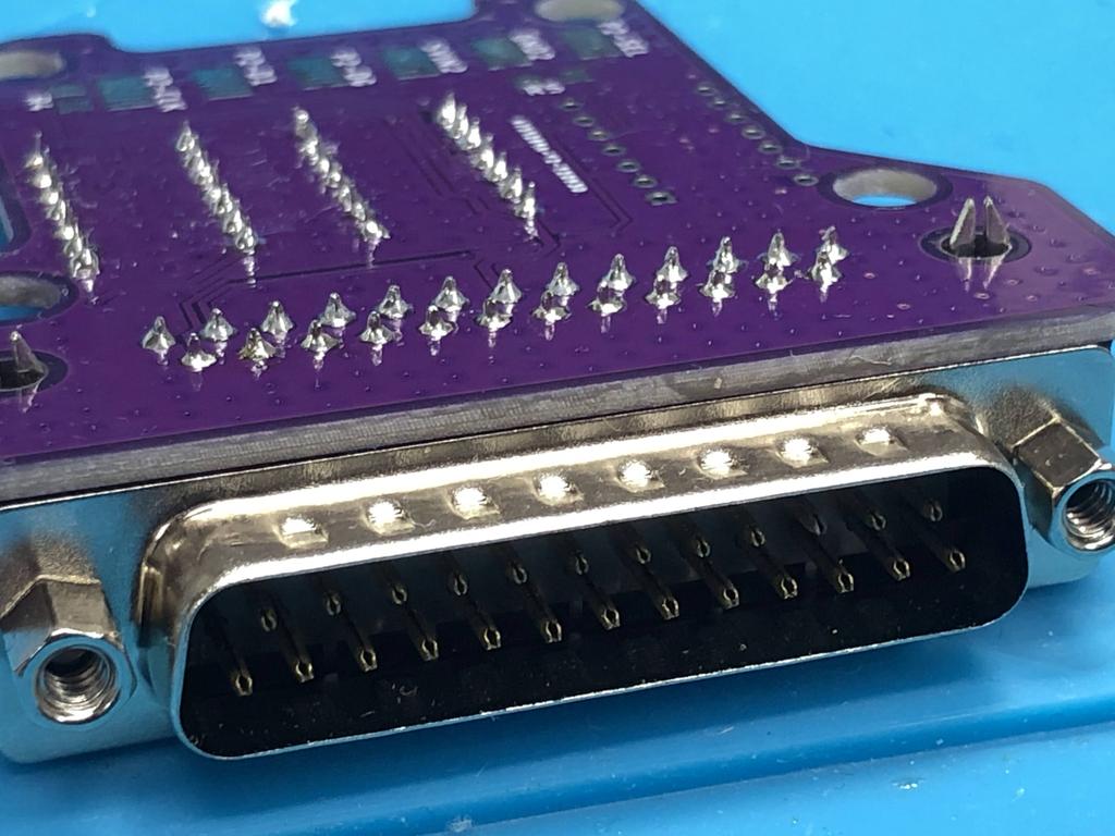
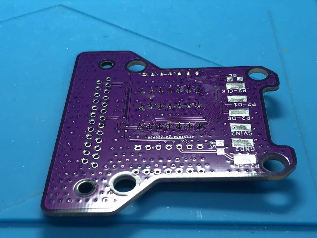
Then I soldered the connector to the PCB. Notice how one of the vias has no pin coming through it:
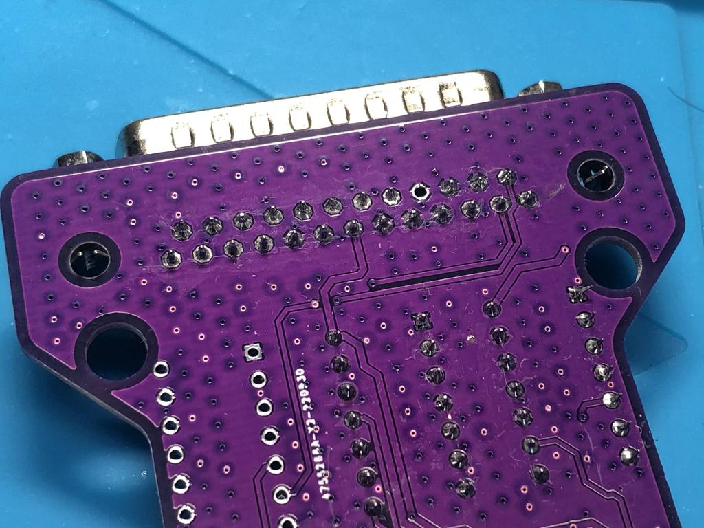
That pin 22 I lifted is visible on the other side:
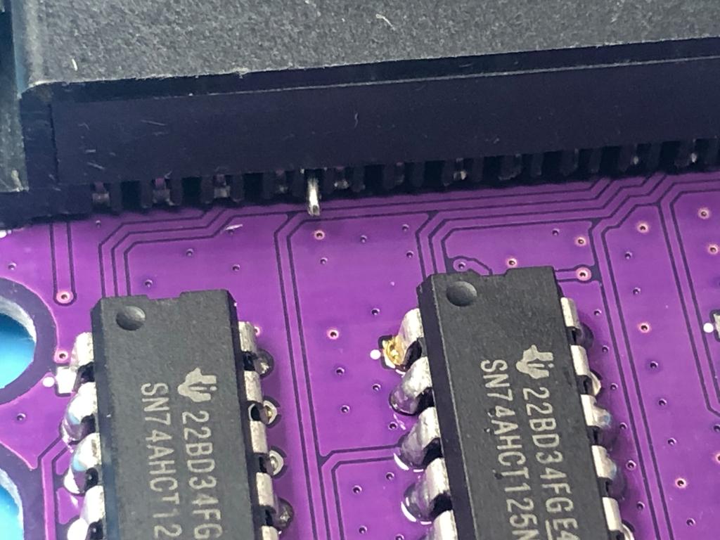
Since we need this to be tied to 3V3, I soldered a short wire from that pin to the 3V3 leg of one of the level shifters:
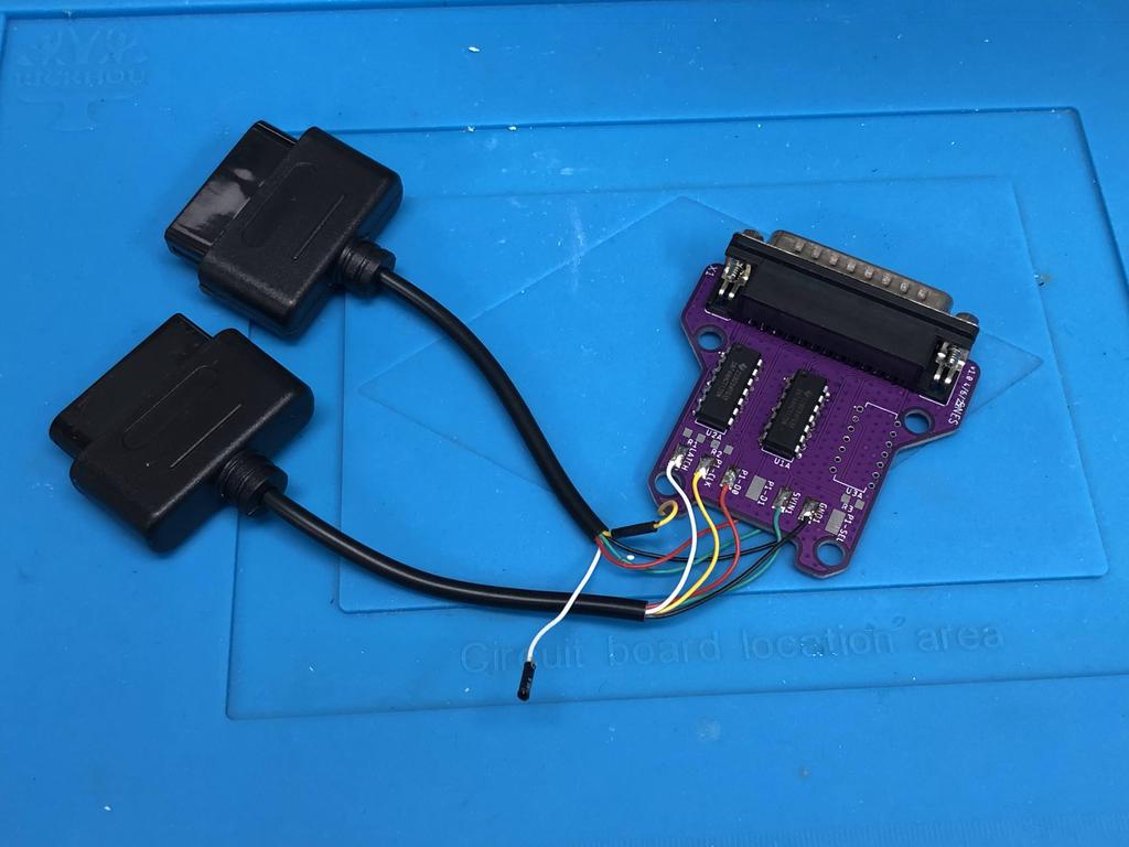
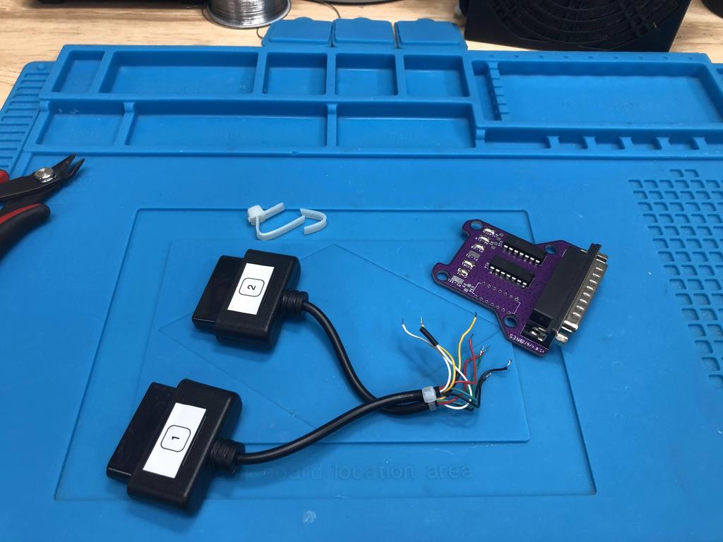
For the cables, I took apart the DIY adapter I had made before:
I stripped and tinned the wires, then passed the cables through the bottom shell:
I soldered the wires to the PCB, starting with player 1:
And player 2:
Finally, I removed the screw posts, added zip tie strain reliefs, and put it all together:
All done!
Thoughts #
I’ve already mentioned multiple times how much I love the BlueRetro project, so I’ll share my thoughts on the difference between these AIO units over the standard DIY through-hole method.
Overall, the main advantages to the AIO units are:
- They’re easier to build, as you get to solder wires to a PCB rather than to pins of a DB25 connector or level shifter.
- It’s easier to get the orientation right when connecting the receiver to the adapter, since the 3D-printed shell has a very clear “top” side that you need to line up.
- They just look nicer with the 3D-printed shell.
The disadvantages are:
- They’re more expensive to make, as you need to get the PCBs and 3D-printed parts made.
- The 3D-printed part models don’t print as nicely with FDM printers. The general shape and small grooves results in long bridges, which despite my best efforts, never looked as beautiful as I hoped.
Having said all that, I’m actually quite happy with these AIO units, and would definitely recommend them!