SNES 2-Chip RGB Filter Mod: SNS-CPU-GPM and SNS-CPU-RGB
A while back, I posted about how I modded my 2-chip SNES, model SHVC-CPU-01, to improve the video output quality using Buttersoft’s filter board, then later posted how user axmcxx performed a similar mod on his SNS-CPU-RGB-02. Well, another user on the ConsoleMods Discord named Toxic_Tripod0 reached out after modding various SNS-CPU-GPM-01/02 models, and graciously shared his pics and steps with me so that I can share it with the community on my blog. He also performed this mod on SNS-CPU-RGB-01/02 models, and we’ll go over some of the improvements he made for these.
SNS-CPU-GPM-01/02 #
Parts #
The list of parts is about the same as for the SHVC-CPU-01, with these differences/extras:
- Cap Kit - $4.95 on Console5
- 35V In 5V Out 2A linear voltage regulator - ~$1.10 each from Mouser
- 470uF 6.3V electrolytic capacitor - included in the Console5 cap kit, or $1.21 for 10 on AliExpress
- 1x 22uF X5R 0805 ceramic caps - $2.90 for 100 on AliExpress
- 11x 10uf X7R 0805 ceramic caps (instead of 8x) - $1.80 for 100 on AliExpress
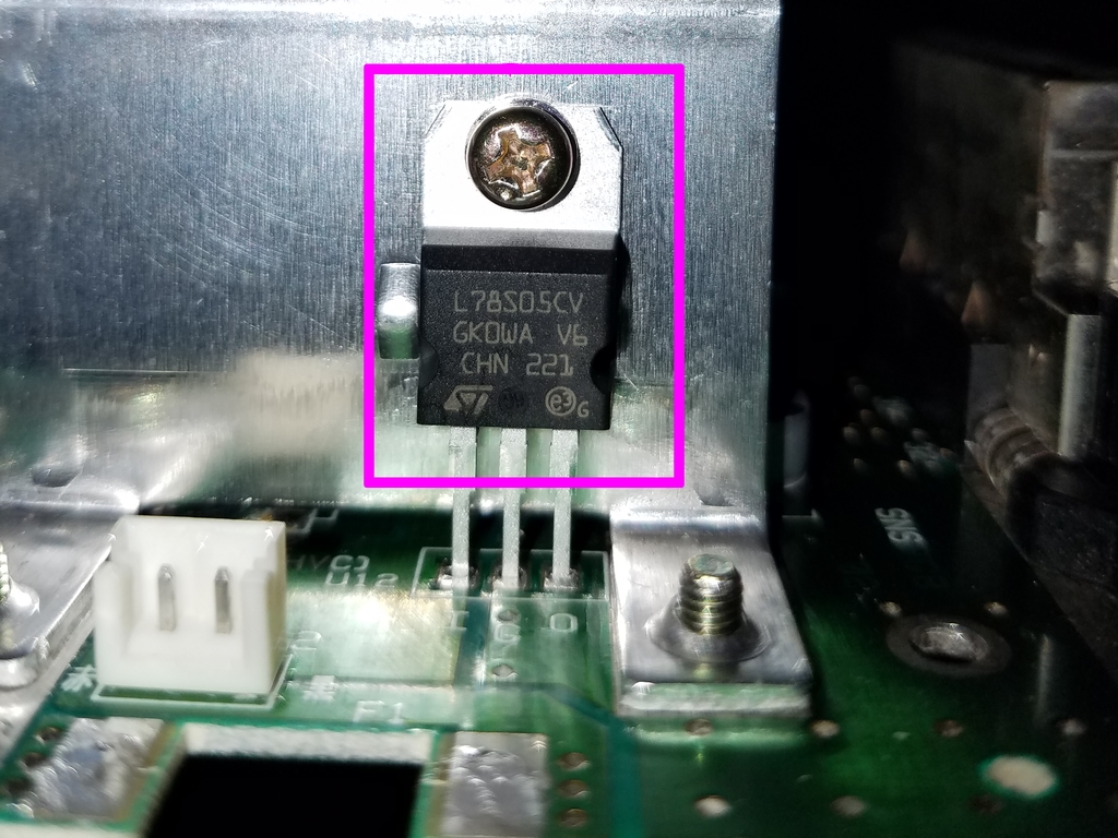
Note that the voltage regulator is difficult to find as they are no longer in production. Look on Mouser, Digikey, eBay, or AliExpress, and make sure it’s rated for 2A - most are 0.5A or 1A, and also rated for 35V input - most are 6.5V. The higher current rating means it runs cooler.
The Build #
Toxic_Tripod0 took apart his SNES, and then recapped it using a capacitor kit from Console5. He recommends this, especially after seeing that upon removal, most caps had leaked underneath. Leaking capacitors indicates that they are no longer working optimally, which not only affect their performance, but can erode and cause damage to the main board. Unfortunately, I don’t have any pics of the recap, but Console5 provides excellent documentation and images to follow.
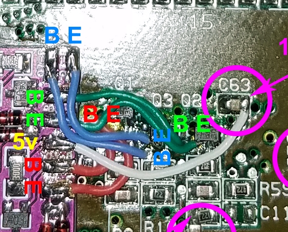
Next, he followed the steps on my first post on how to populate the filter board PCB. As with the SHVC-CPU-01, he removed and transferred the 3 transistors - this time at locations Q3, Q4, and Q5 - to the PCB, and wired them up:
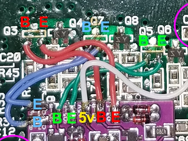
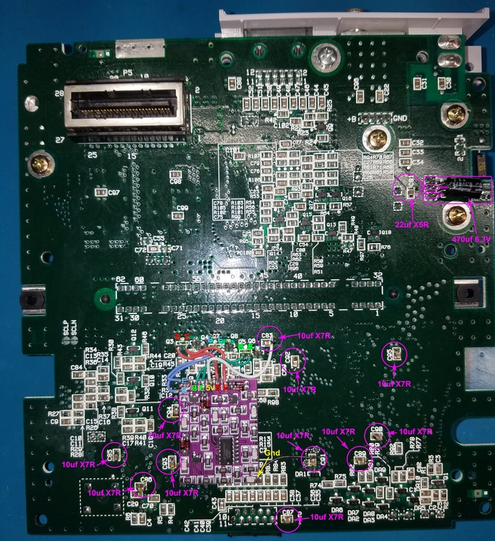
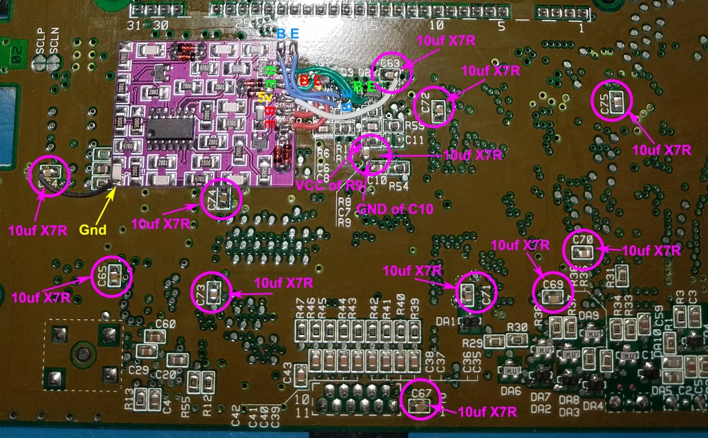
Next, he stacked the eleven 10uF ceramic caps on top of the existing ones at these locations (he actually recommends replacing them entirely rather than stacking):
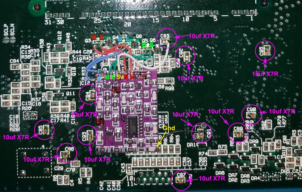
In the picture above, we can also see that the 5V supply for the PCB is connected to the right-hand side of C83, while the board’s ground is connected to the top of C91.
Here is where we diverge from the previous posts. The original voltage regular is known to produce enough noise or ripple that it can result in a single thick white vertical line across the screen. To address this, Toxic_Tripod0 replaced the regulator with a new one:
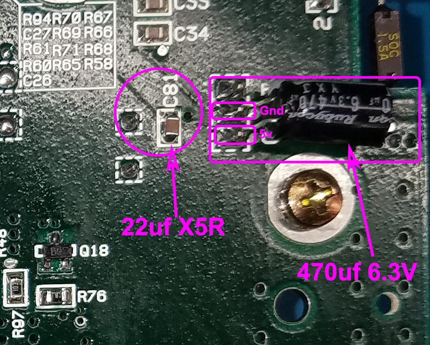
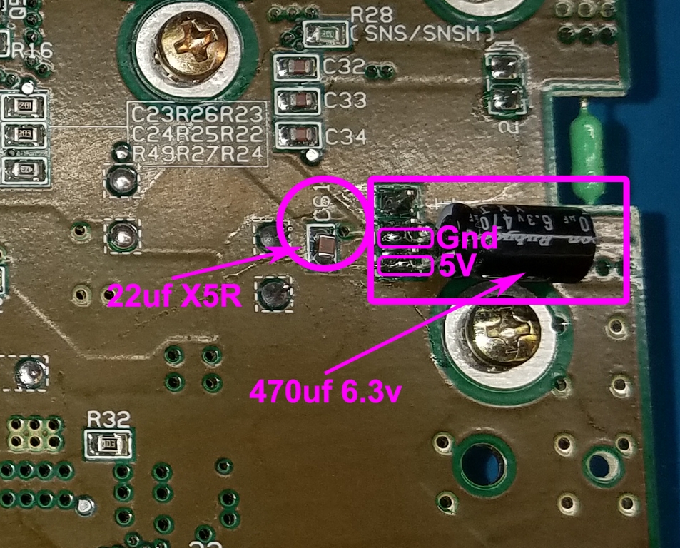
Finding a new regulator can be difficult, so another option, as described on RetroRGB, is to add a 470uF electrolytic capacitor between the 5V and GND pins of the regulator, and to replace the 1uF cap next to it with a 22uF one. Toxic_Tripod0 had already replaced the regulator, so doing this mod was not really necessary, but since the Console5 cap kit came with the 470uF cap, he went ahead and did it anyway:
Note that even if the SNES does not display the thick white line, Toxic_Tripod0 found that doing this mod helped to dim the faint vertical lines (“jailbars”) that he was seeing.
Finally, he lifted pin 27 on PPU2, as this has the greatest impact on reducing jailbars:
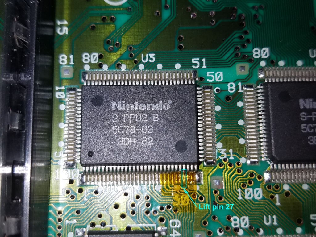
Note that Toxic_Tripod0 did not lift pin 3 on PPU2 because he did not notice any diagonal lines, as is common on SNS-CPU-RGB models. Lifting pin 3 results in the composite and s-video signals losing their color signal, so it’s better if it can be avoided.
Here’s a complete picture of all the mods made to the underside of the main board:
SNS-CPU-RGB-01/02 #
As I’ve already covered axmcxx’s mod of a SNS-CPU-RGB-02 before, we’ll focus on the differences here.
Parts #
As usual, get the parts listed for the SHVC-CPU-01, with these differences/extras:
- Cap Kit - $4.95 on Console5
- 3x extra transistors (2SA1037AKT146Q) - $0.30 each from Digikey
- 35V In 5V Out 2A linear voltage regulator - ~$1.10 each from Mouser
- 470uF 6.3V electrolytic capacitor - included in the Console5 cap kit, or $1.21 for 10 on AliExpress
- 1x 22uF X5R 0805 ceramic caps - $2.90 for 100 on AliExpress
- 12x 10uf X7R 0805 ceramic caps (instead of 8x) - $1.80 for 100 on AliExpress
Unlike the SHVC-CPU and SNS-CPU-GPM models, we need to leave the 3 transistors on the main board, which is why 3 more need to be bought.
The Build #
Toxic_Tripod0 took apart his SNES and recapped it using the kit from Console5. Next, he followed the steps on my first post to populate the filter board PCB, this time installing the three new transistors on the PCB.
On the main board, he lifted the ‘base’ leg of each of the three transistors at Q1, Q2, and Q3, and then wired up to the mod board as follows:
Here’s a pic from axmccx’s install that shows more clearly how to lift the transistor legs, using some kapton tape to ensure it doesn’t short with the pad on the main board:
![]()
Next, he replaced the twelve 10uF ceramic caps at the following locations:
Above, we can also see that the 5V supply for the PCB is connected to the right of C63, while ground is connected to the left of C64. Also, the 10uF cap that sits between R9 and C10 is actually floating - there are no pads to solder to:
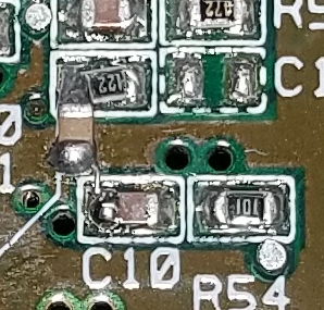
Toxic_Tripod0 used a wire to bridge the gap between the two locations, as the cap is too small. If you have a 1206 10uF capacitor, it might fit better. The reason for this capacitor is that on the schematics for the SHVC-CPU model, there is a filter cap between the green line at that point and ground, but this cap is missing from the SNS-CPU-RGB models entirely.
As with the SNS-CPU-GPM, he then replaced the voltage regulator:
On the underside of the board, where the three pins of the voltage regulator are soldered, he added a 470uF electrolytic capacitor on the 5V and GND pins of the regulator, and also replaced the 1uF ceramic cap at C61 with a 22uF X5R:
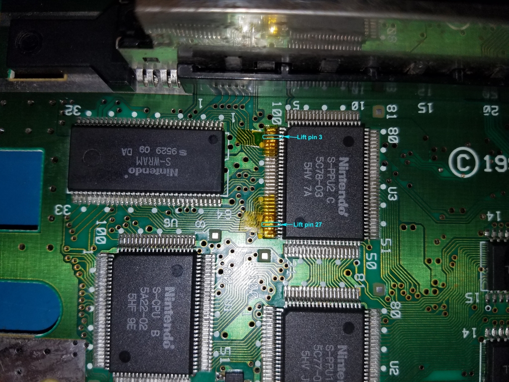
Finally, he lifted pins 3 and 27 on PPU2, to fix diagonal lines and jailbars respectively:
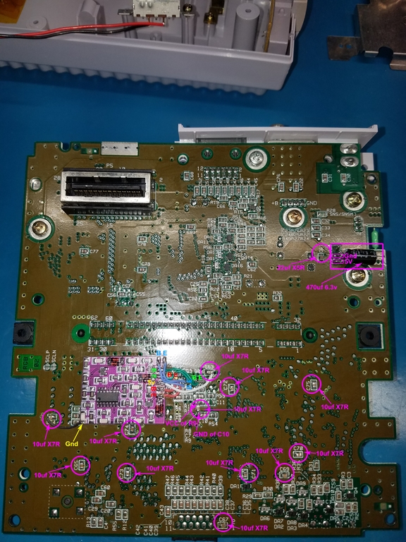
Here’s a complete picture of all the mods made to the underside of the main board:
Summary #
I thought it might be useful to summarize all the mods made along with what they fix in a table:
| Modification | What it fixes |
|---|---|
| Recapping the top side of the board | Saves main board from damage, and may clean up signals. |
| Installing the filter board | Reduces blur and ghosting in video output. |
| Replacing/stacking 10uF ceramic caps | Further helps in reducing noise in video output. |
| Replacing voltage regulator | Helps reduce thick white line across the screen, as well as jailbars. Also runs less hot, so may prolong lifetime of caps underneath the regulator’s heatsink. |
| 470uF cap on voltage regulator | Can be used instead of replacing the original voltage regulator, though less effective. |
| Replacing 1uF cap with 22uF cap next to regulator | Further helps in reducing the thick white line across the screen. |
| Lifting pin 3 on PPU2 | Reduces diagonal lines. NOTE: composite and s-video output lose their color signal. |
| Lifting pin 27 on PPU2 | Most effective at reducing jailbars. |
Thoughts #
Unfortunately, Toxic_Tripod0 did not take before/after pics, as he felt that it was difficult to see the differences this way. However, we can expect that the differences should be at least as good as what I’ve shown in the previous two posts, if not better considering the extra mods that were made. Toxic_Tripod0 told me that in person, the video output from his modded SNS-CPU-GPM looks identical to the 1-chip or the Jr.
Anyway, our hope is that this post is useful to those looking to perform a similar mod. Huge thanks to Toxic_Tripod0 for sharing his pics and experience!