Making a gbs-control video scaler
I’ve been playing most of my retro consoles on my 20” CRT, which has been great, but there are times - like when playing four-player Micro Mages on the NES - when you really want to play on a big screen. Unfortunately, older consoles like the NES output a 240p image, and newer TVs like my 70” 4K don’t accept this low resolution signal. The fix is to use a scaler, like the RetroTINK or OSSC to scale up the resolution to at least 480p, but these always seemed a bit expensive. Then I watched this video from Voultar where he shows how to build a scaler for about $35 USD.
The project is called gbs-control, and it’s basically a mod of the GBS8200, a cheap scaler that was apparently developed for arcade owners to convert their cabinets from using CRTs to LCD panels. The scaler itself is apparently not very good on its own, but Robert Neumann developed an open-source firmware that you can flash on the popular (and cheap) ESP8266 microcontroller, and wire up to a GBS8200 to take control of it and make it a much better scaler. Check out the README for more details.
UPDATE 2023-11-07: For a more in-depth install, check out my more recent post on building a gbs-control.
Parts #
I ordered the parts I needed:
- GBS8200 board (eBay $22 USD)
- ESP8266 board (AliExpress $4 USD)
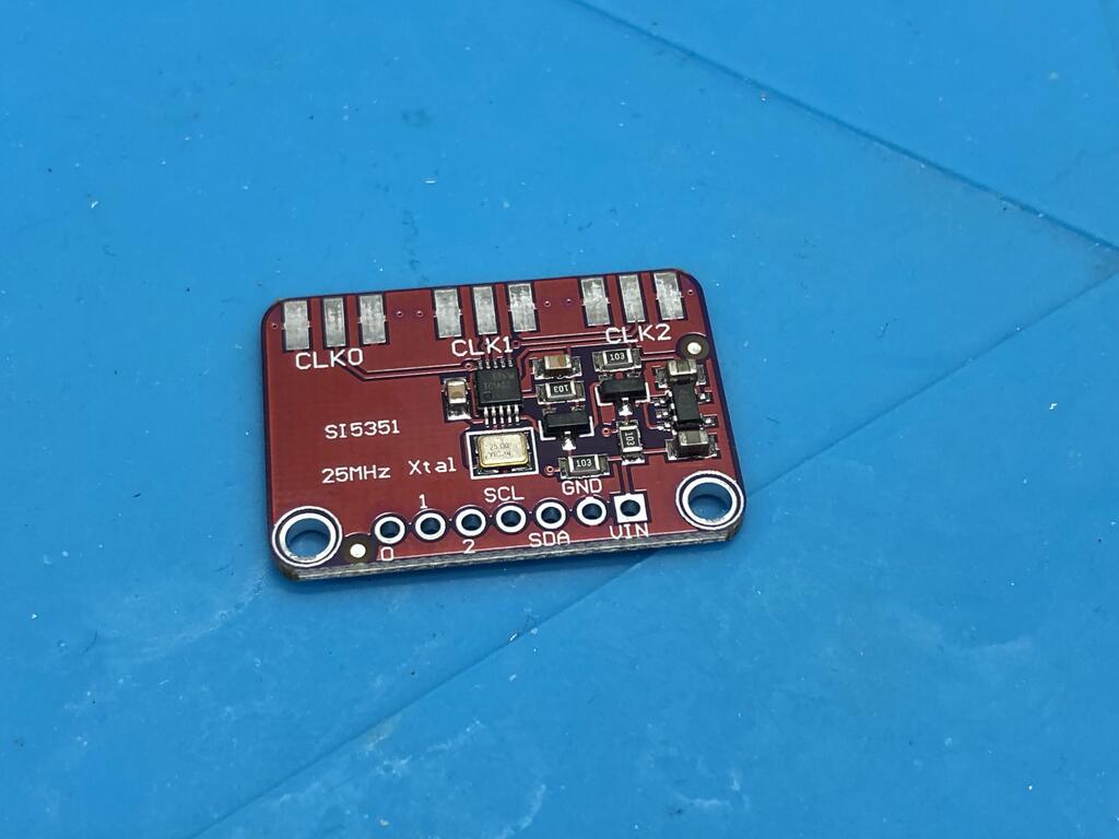
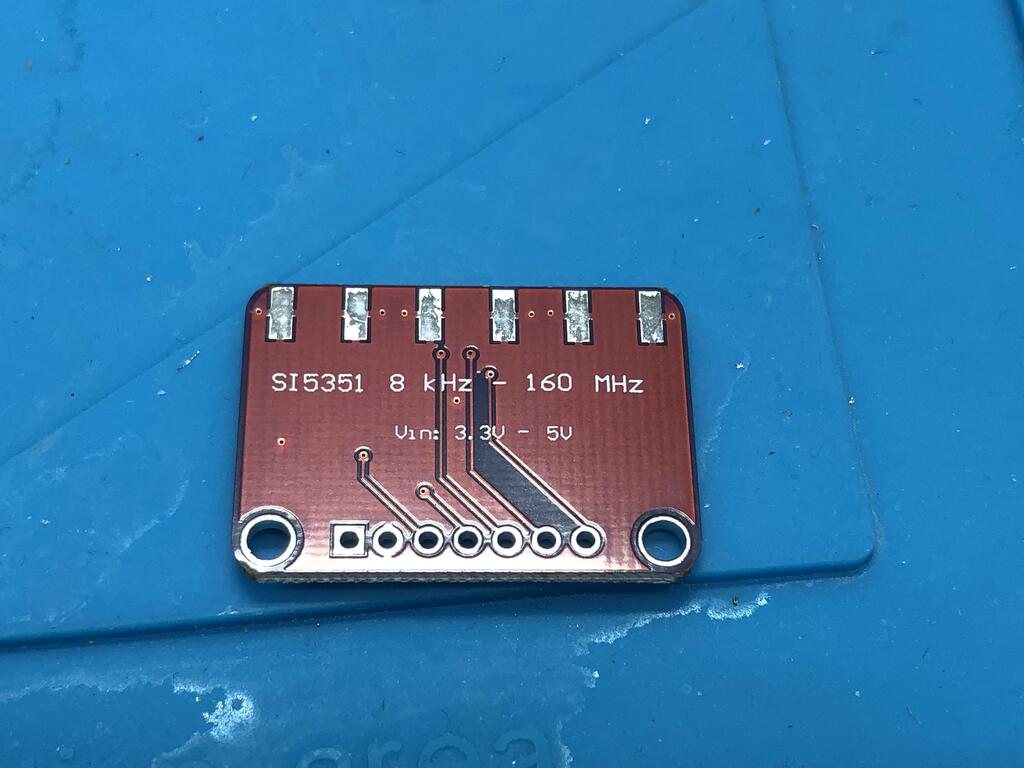
- Si5351A Clock Breakout Board (AliExpress $4 USD)
- 0805 SMD 10uF caps (AliExpress $2 USD for 100 pcs)
- VGA male to HDMI female converter (AliExpress $4.30 USD)
The Build #
Mostly following Voultar’s video, along with reading the official instructions on how to build the hardware, it wasn’t very hard to put this project together.
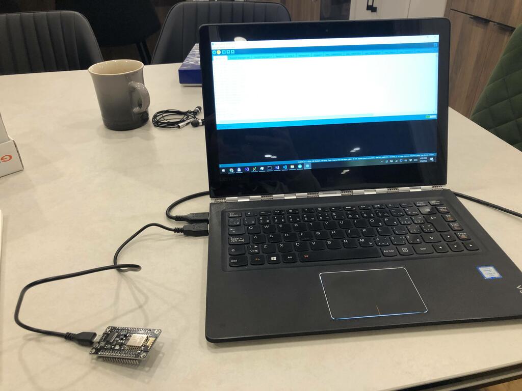
First order of business, load up the firmware onto the ESP8266:
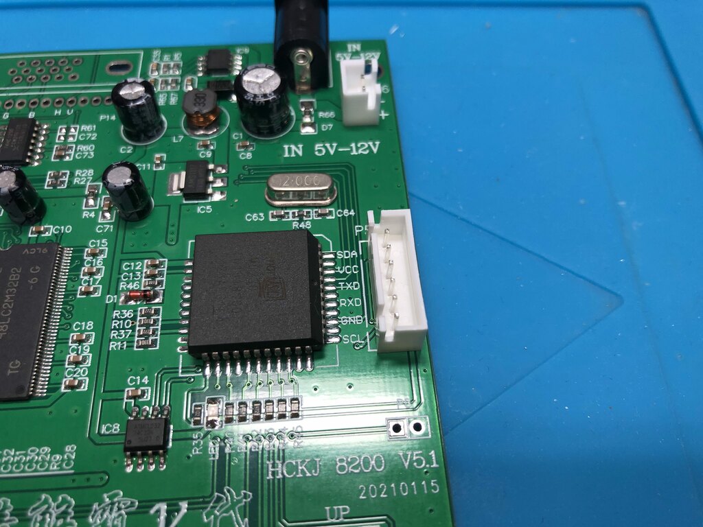
Then I removed the socket on the side of the GBS8200 board:
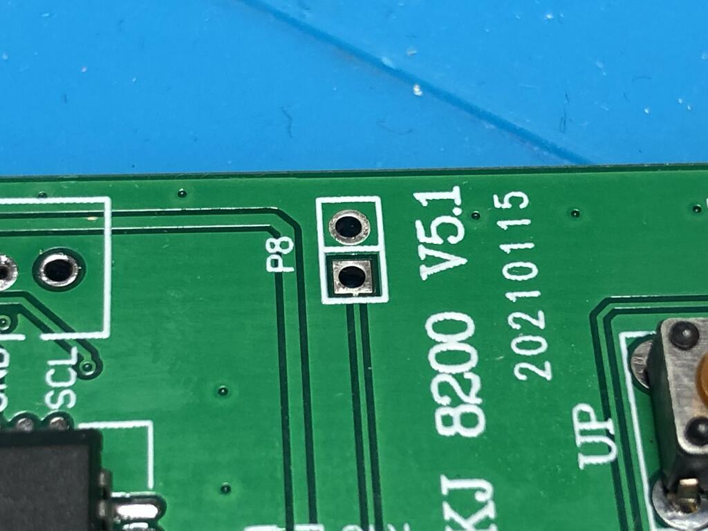
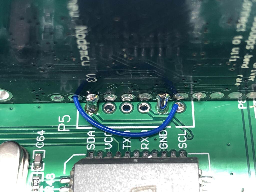
Next I bridged P8 to enabled debug mode, which allows the ESP board to take control (see the next photo for where it’s actually bridged):
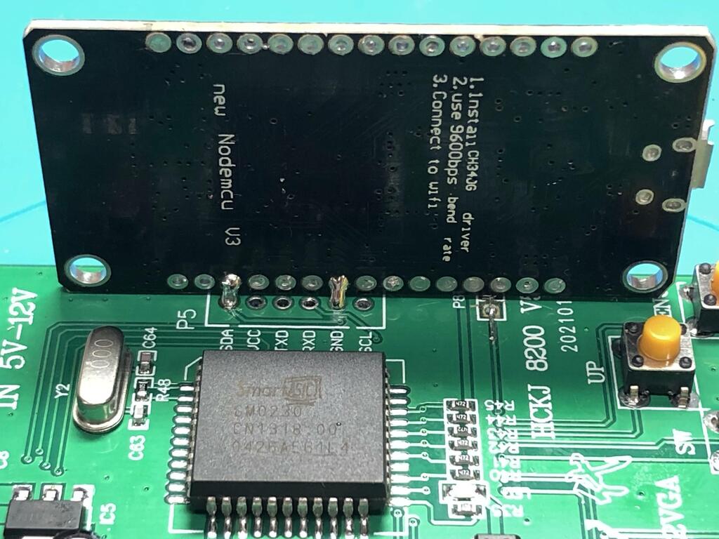
Following Voultar’s method, I soldered the ESP board sideways onto the GBS board:
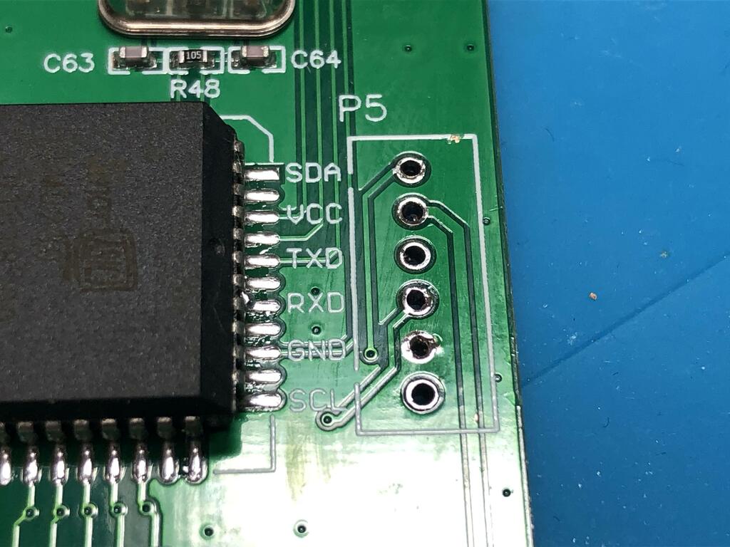
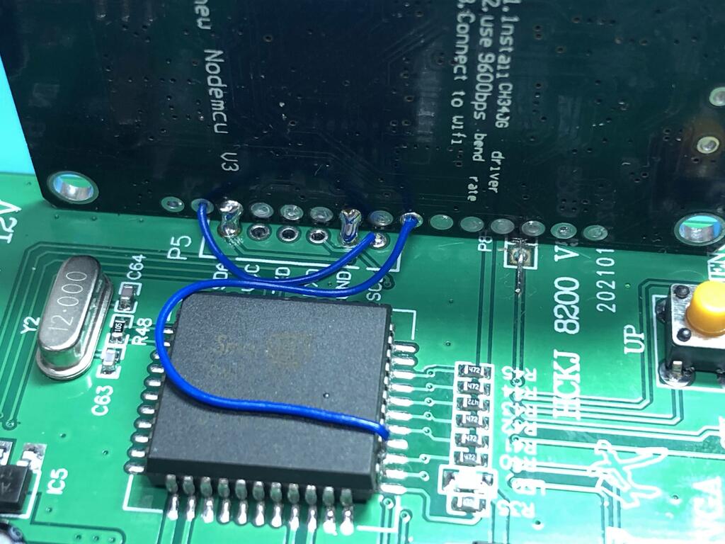
Soldered the necessary connections:
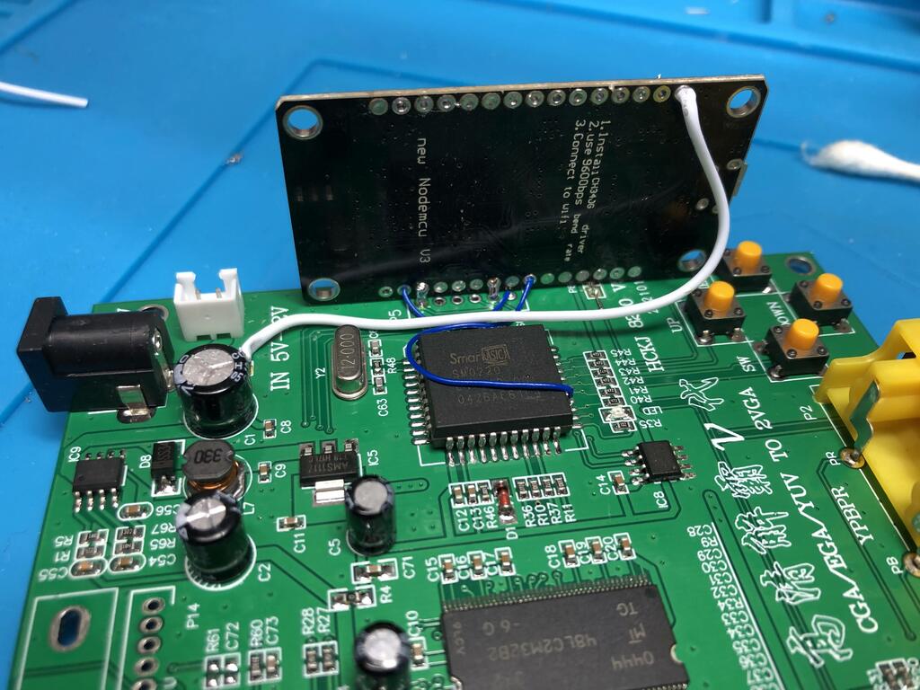
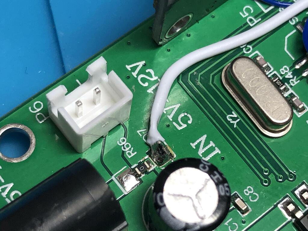
I connected the 5V DC input barrel jack to the ESP board:
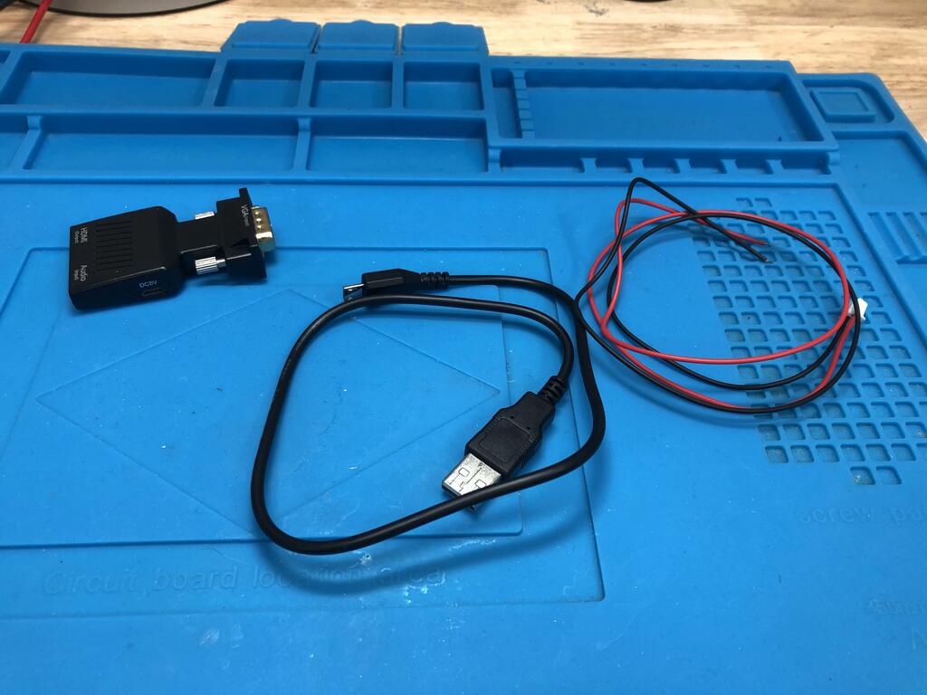
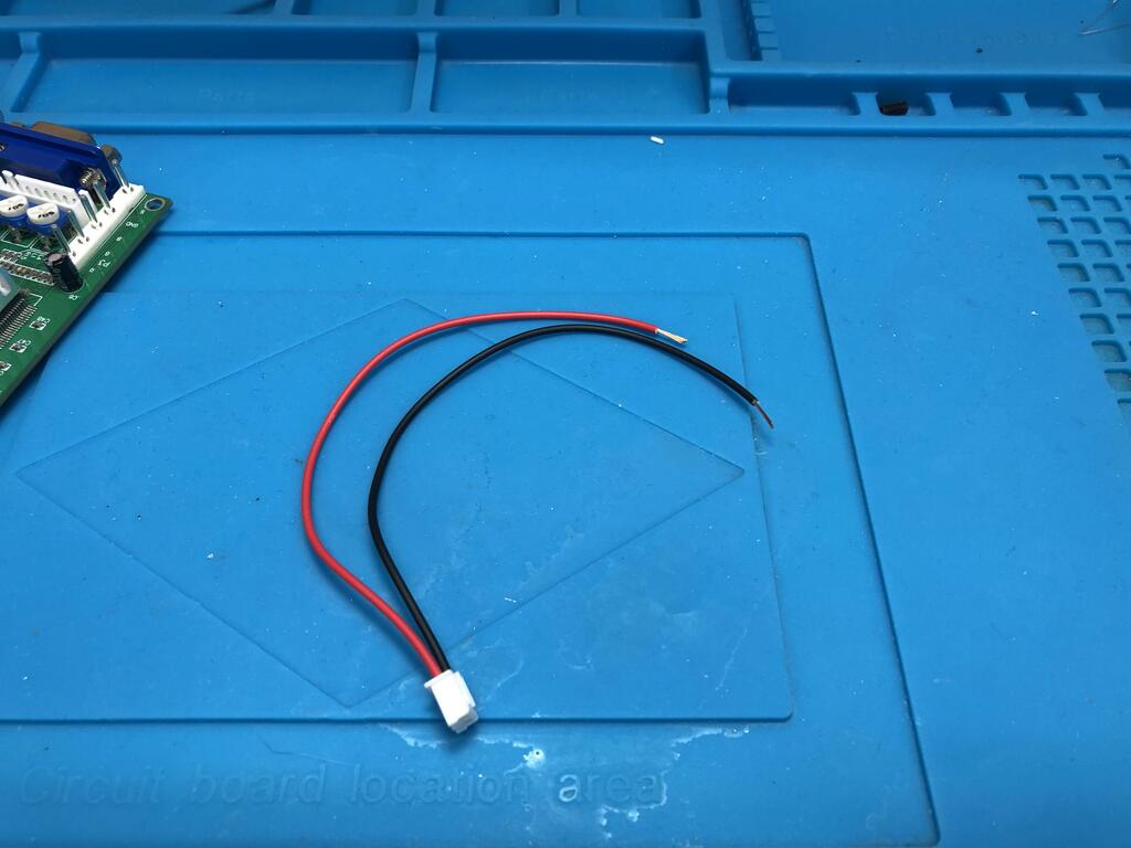
The VGA to HDMI converter needs 5V as well. Using the USB plug that came with the converter, and the pig tail that came with the board, I spliced them together:

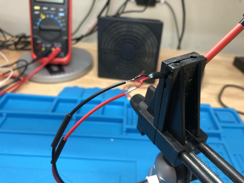
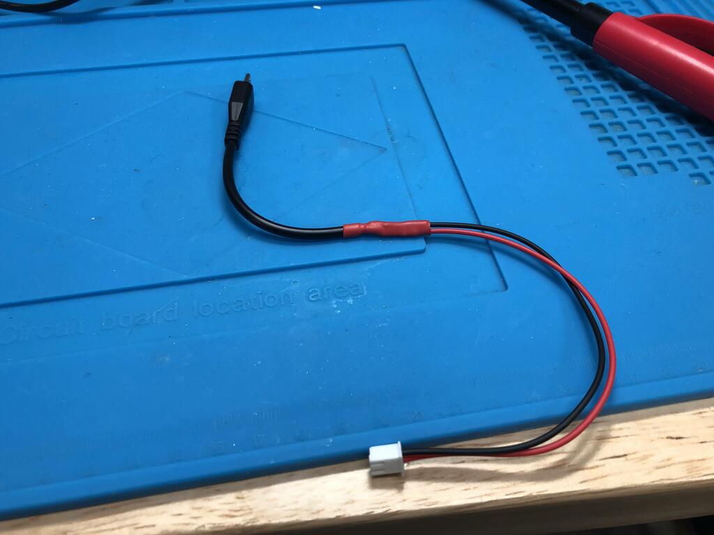
Now we can easily power the converter:
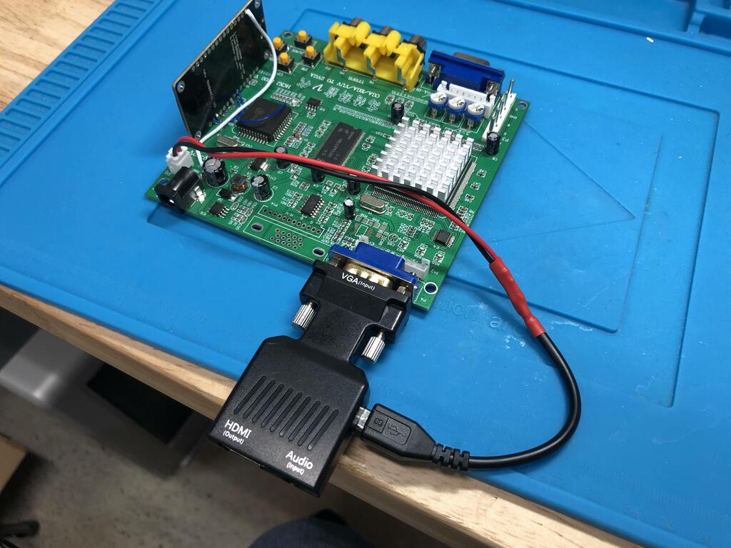
Time to put everything together and perform a quick test:
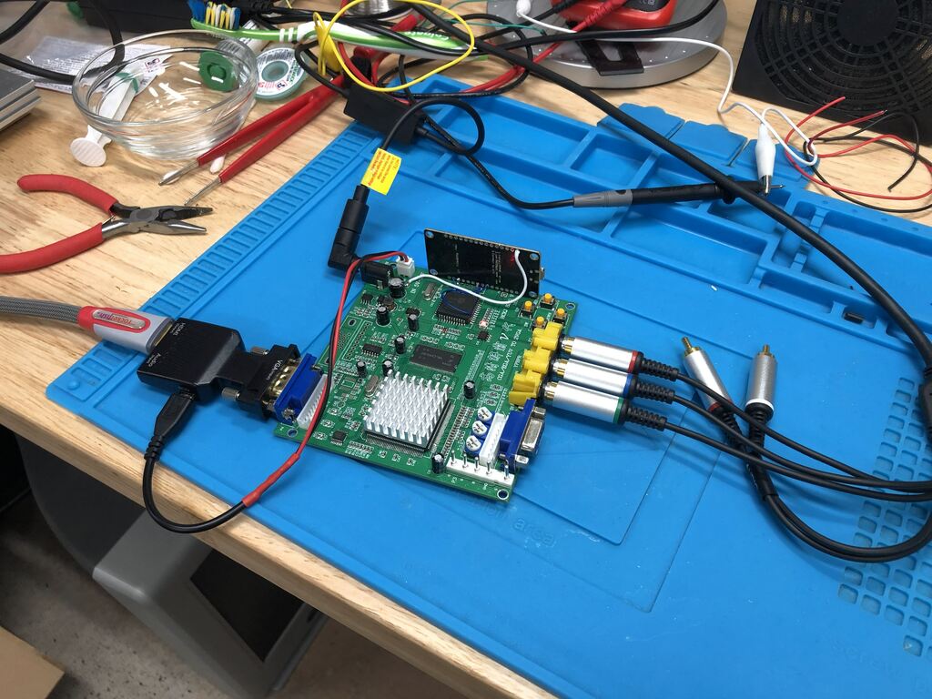
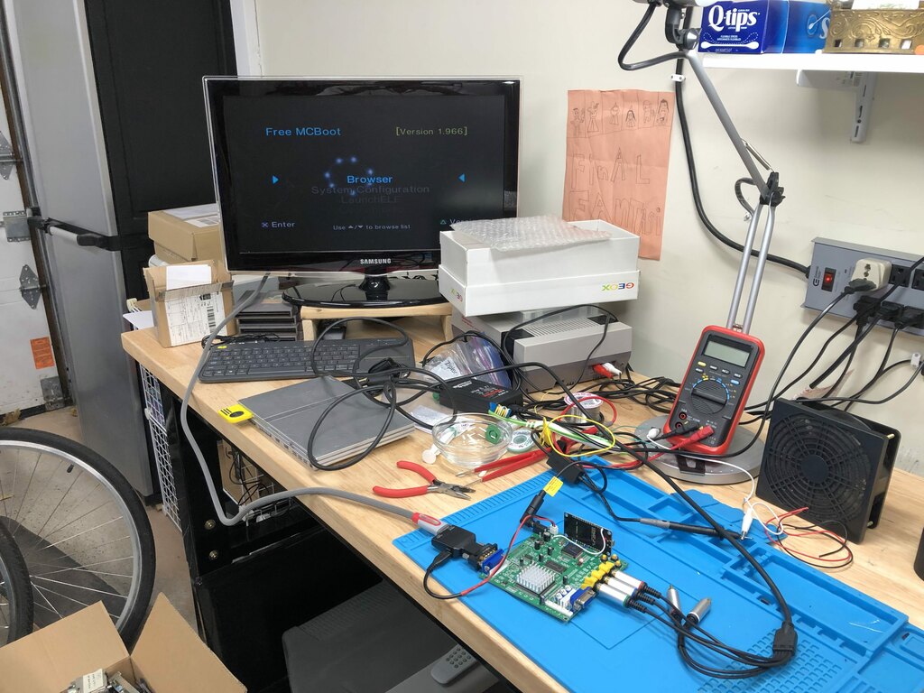
Success! This is a PS2 connected via component into the GBS, and the GBS outputting 1080p over HDMI.
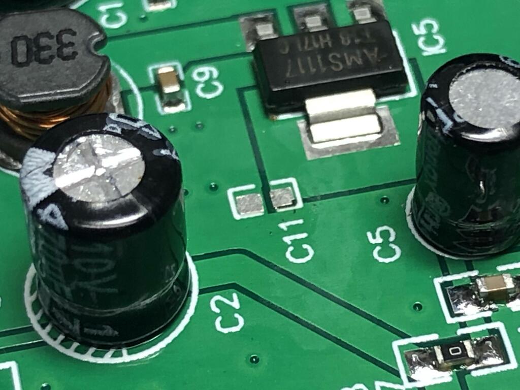
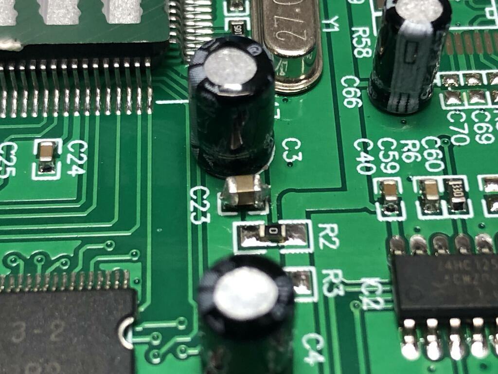
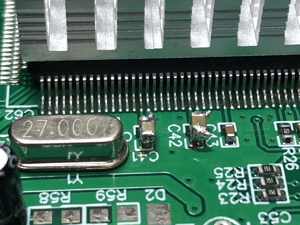
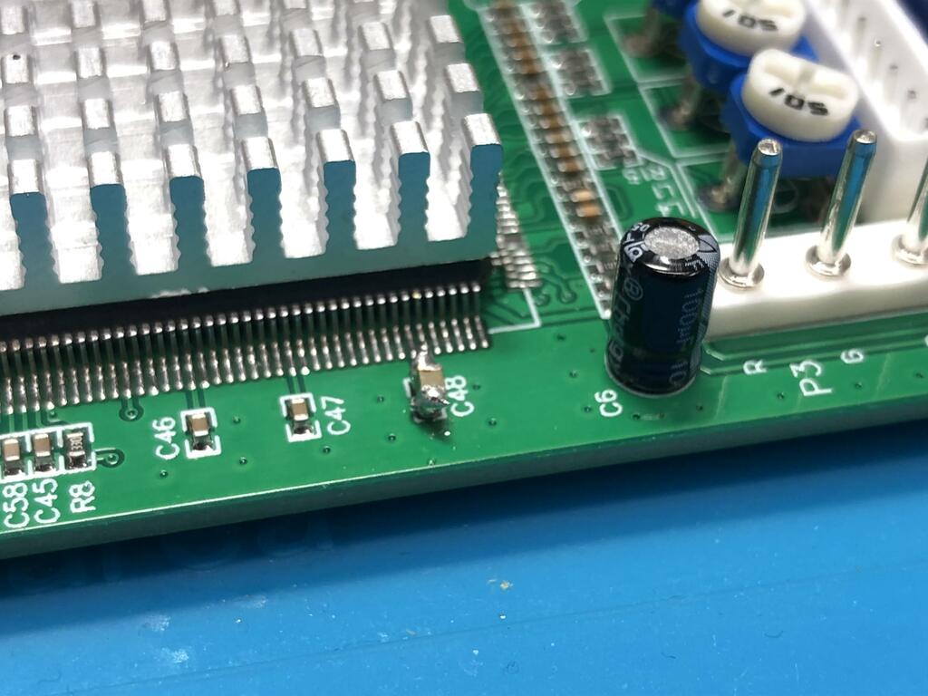
Next up was removing some caps and stacking some to improve the GBS performance and filtering:
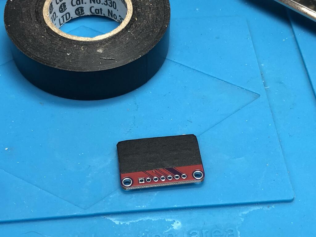
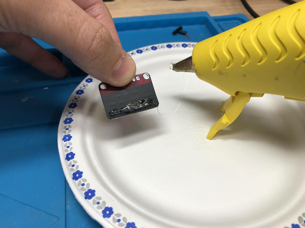
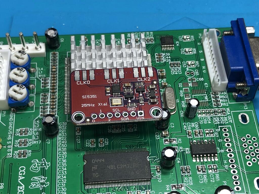
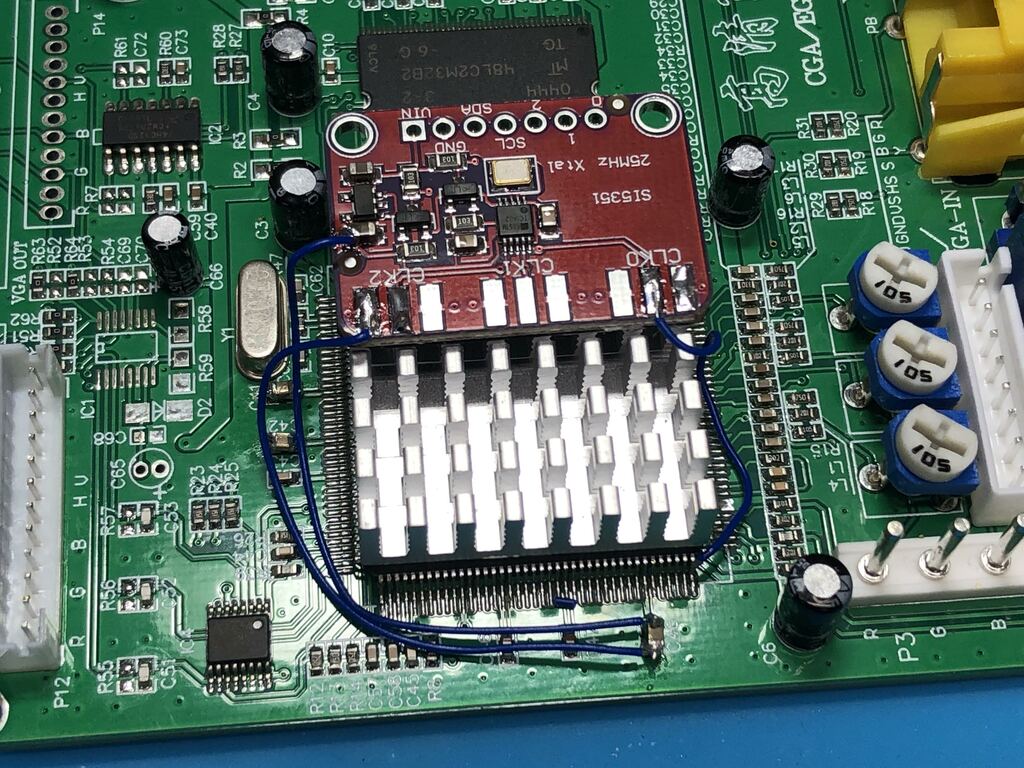
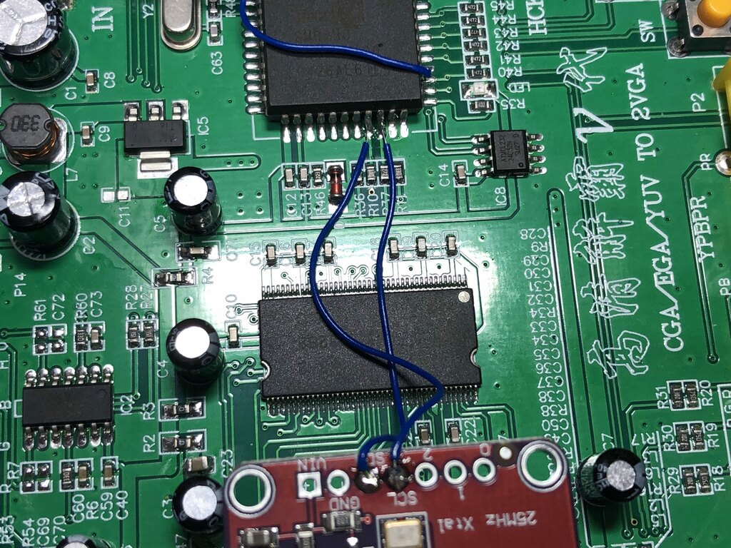
Next I installed the clock generator board which apparently fixes horizontal tearing at high resolutions:
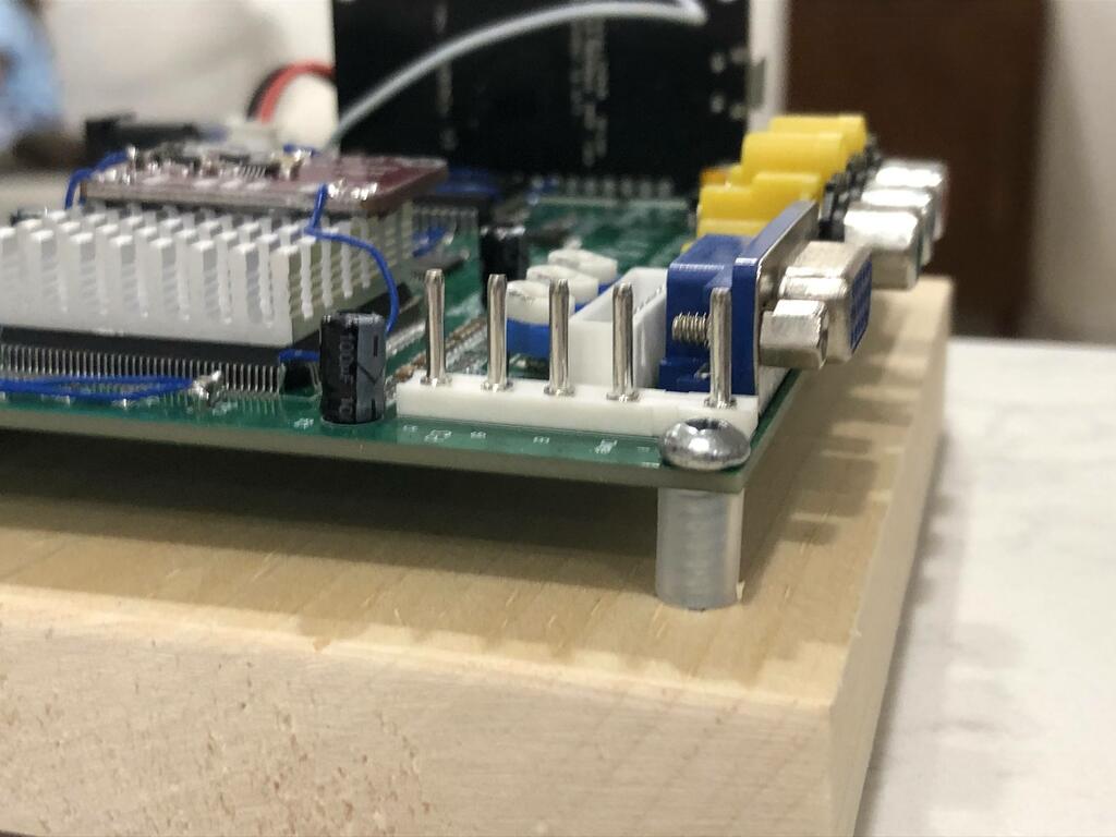
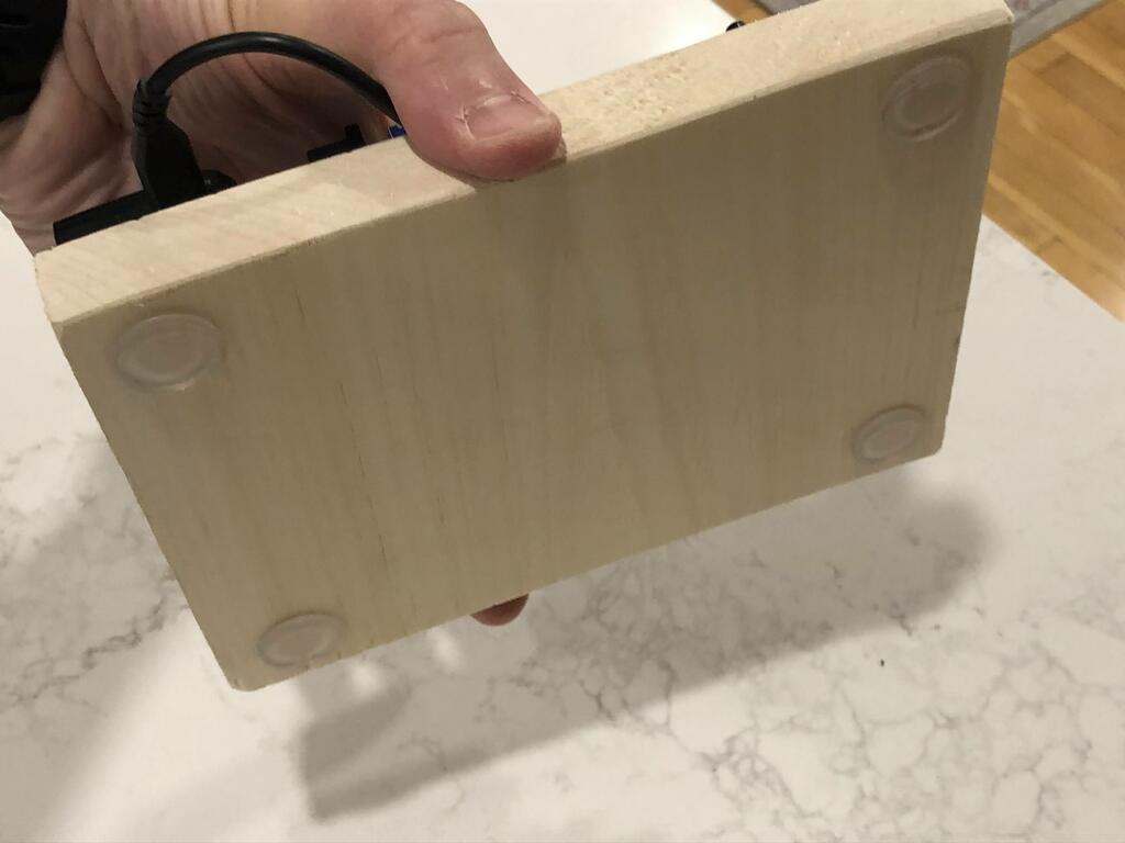
Finally, with everything wired up, I decided to mount it on a piece of wood I cut and sanded:
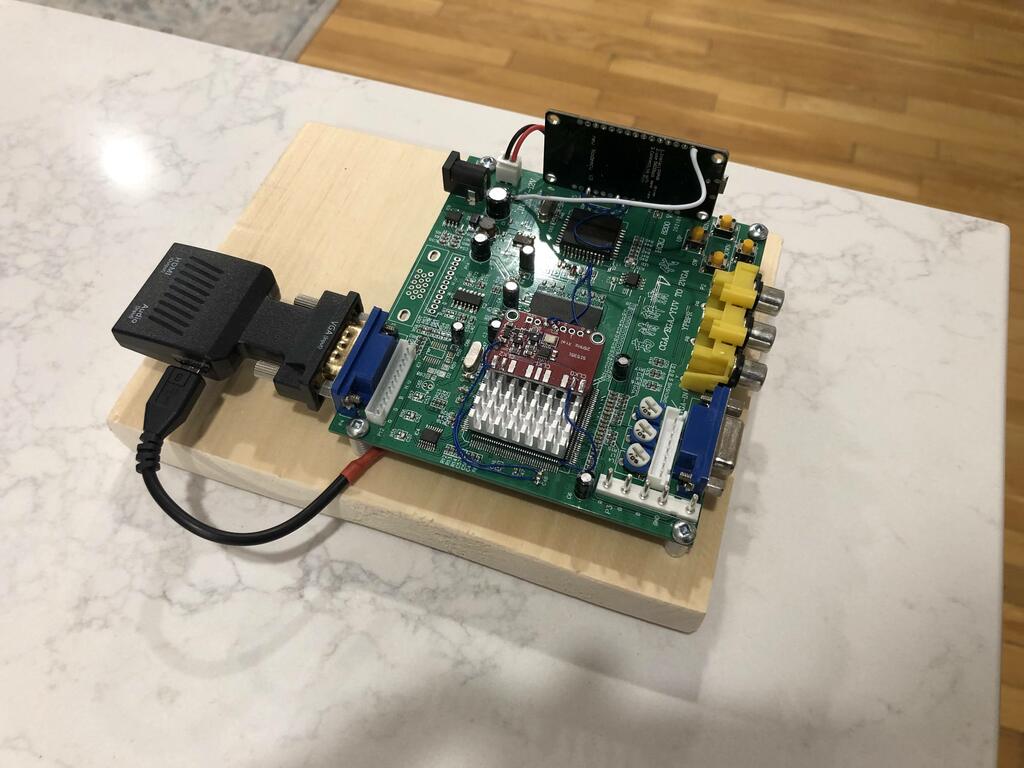
Note that although it’s not shown in the pics, I also attached a dual RCA female to phono male cable to the VGA to HDMI converter to be able to mix in stero audio into the HDMI signal.
Thoughts #
This was a super fun build to make. There are a lot of steps, but it’s not too difficult. The scaler itself works amazingly well! You can connect to the ESP board over WiFi to configure options like resolution, scanlines, and much more. When connecting my NESRGB-modded NES to to via component, the image quality on my 70” TV is crisp and clear. I definitely recommend building one of these!