gbs-control - Take 2
A while ago, I wrote about how I built a gbs-control scaler. Although that post covers the basics, I mostly glossed over the details, expecting the reader to watch Voultar’s video. In this post, I’ll go over how I built a second gbs-control in a lot more detail, which should help anyone who wants to build one, and who prefers a web page to a video.
The Build #
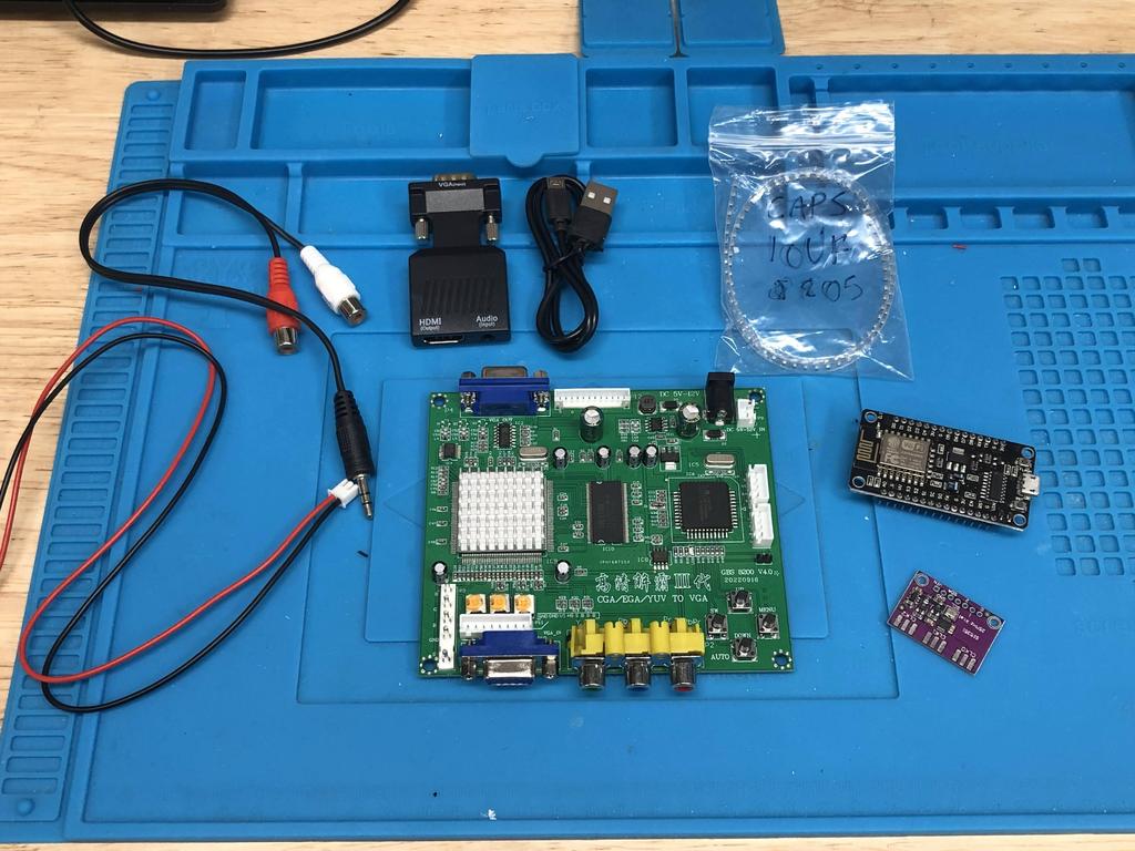
As before, I ordered the parts I needed:
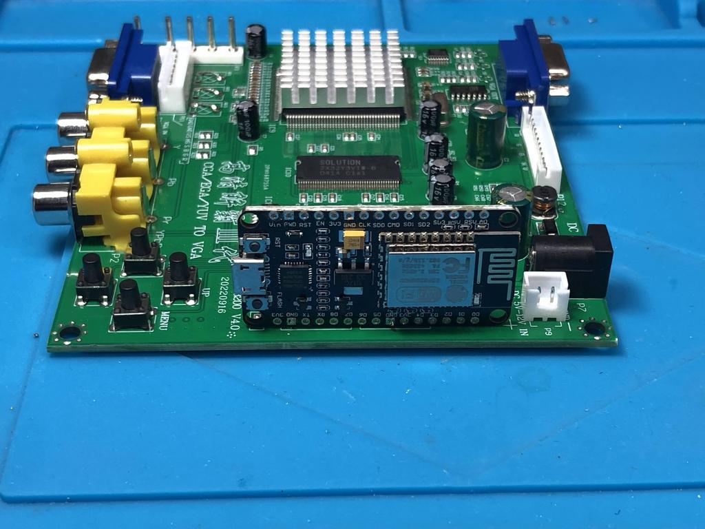
- GBS8200 board - V4.0 only (eBay $22 USD)
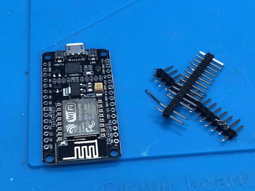
- ESP8266 “NodeMCU” board (AliExpress $4 USD)
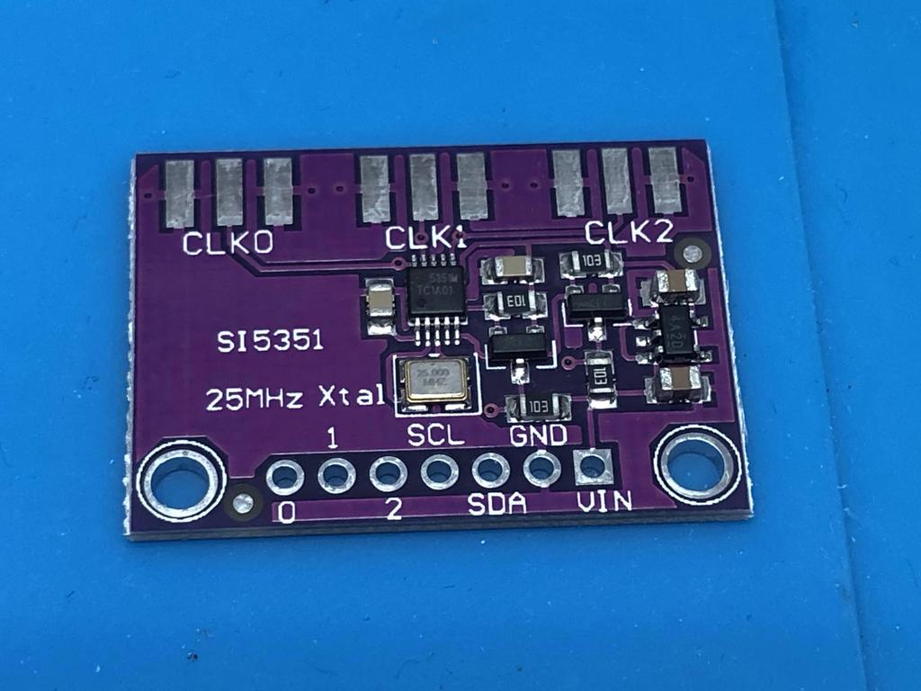
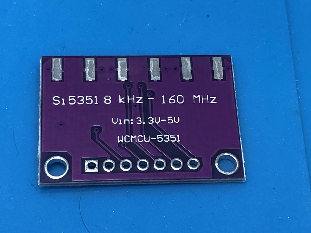
- Si5351A Clock Breakout Board (AliExpress $4 USD)
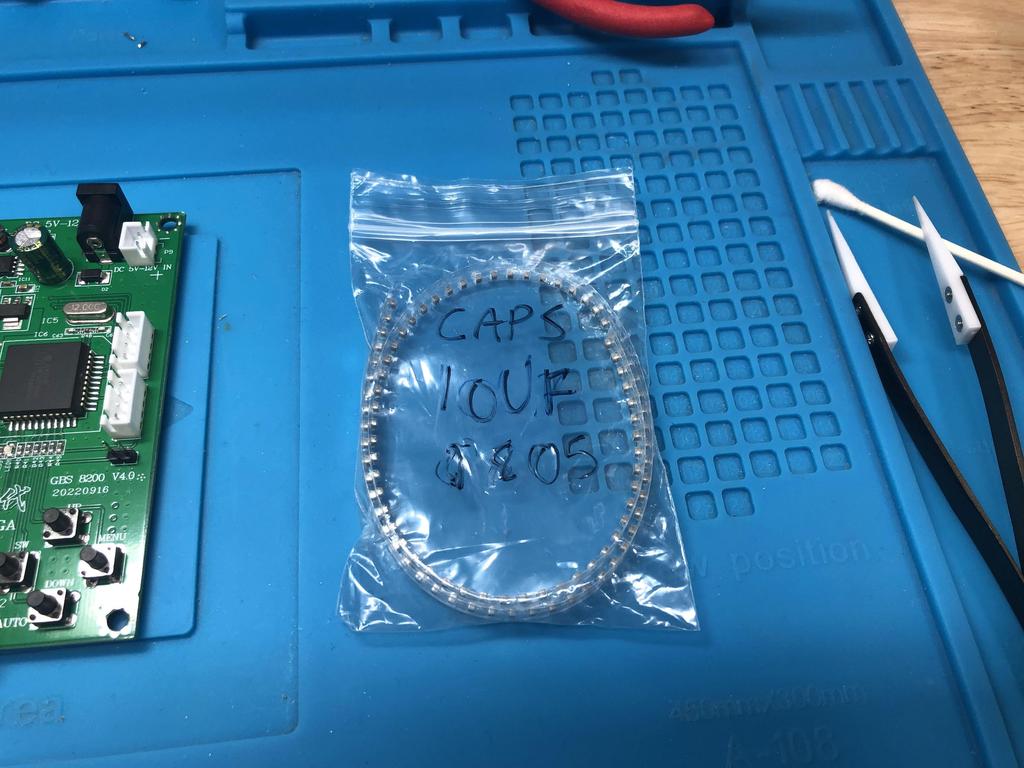
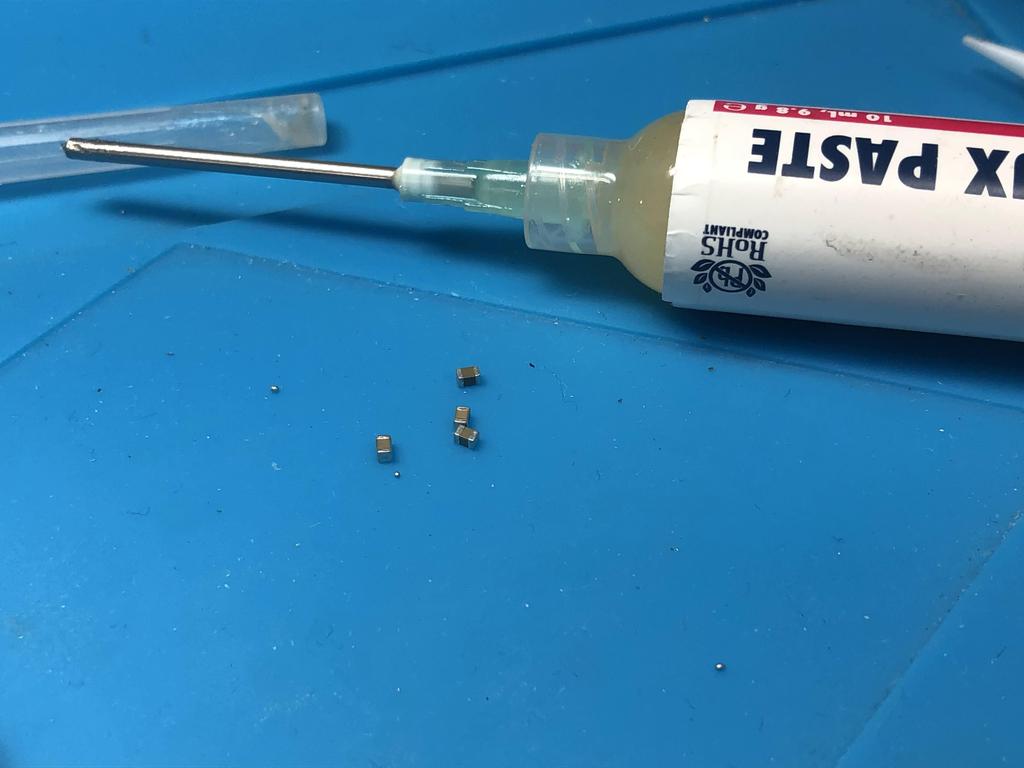
- 0805 SMD 10uF caps (AliExpress $2 USD for 100 pcs)
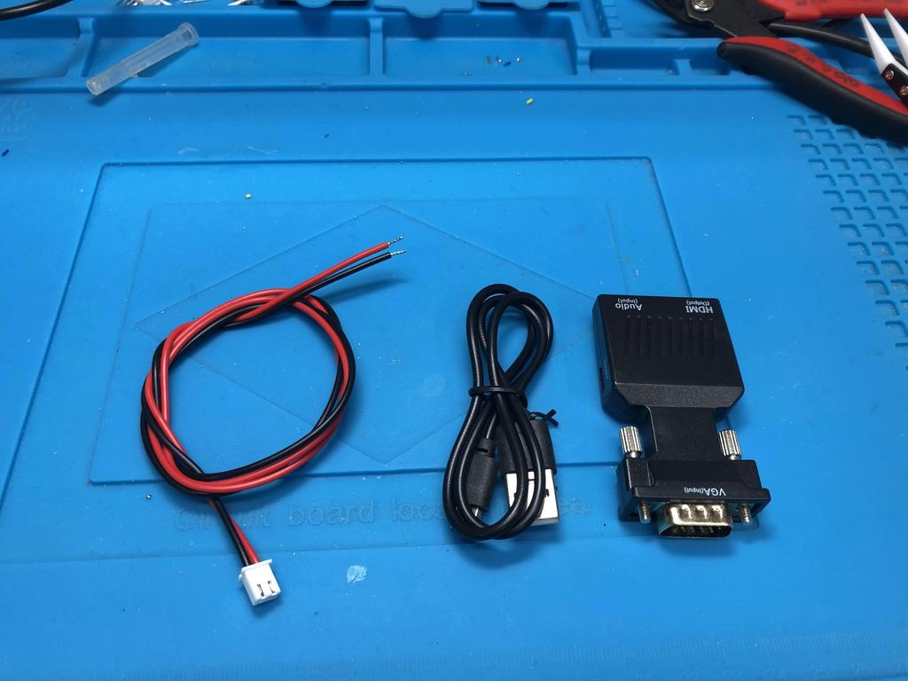
- VGA male to HDMI female converter (AliExpress $4.30 USD)
- A good 5V 2A DC power adapter (Amazon $15 USD)
Note that I highly recommend getting a V4.0 GBS8200. Other variants, like the V5.0, also work, but produce a noisy picture. Unfortunately, I know that this is true from experience. I built two gbs-controls, one with a V4 and one with a V5, and the latter produces such a noisy picture that I ordered a third V4 to replace it. In this build, I’ll be using the V4.
GBS8200 Prep #
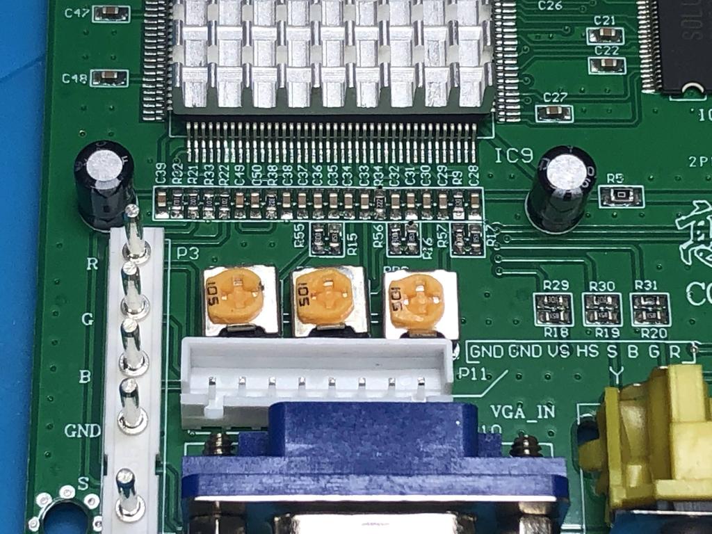
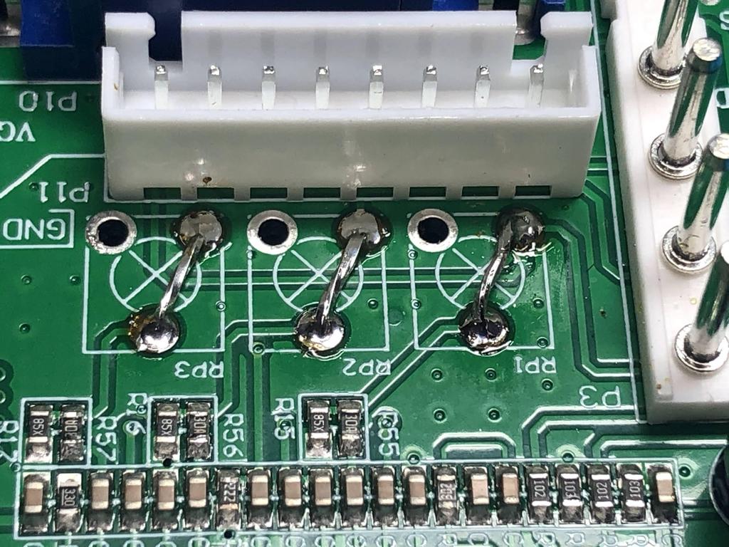
The first thing we need to do is make some modifications to the GBS8200 board itself. We start by removing the three RGB input potentiometers. These pots can be used to tweak the brightness of the RGB values coming in on the DB15 input. This step is technically not required, but even with the pots turned all the way down, they still apply a little resistance, making the video output slightly darker.
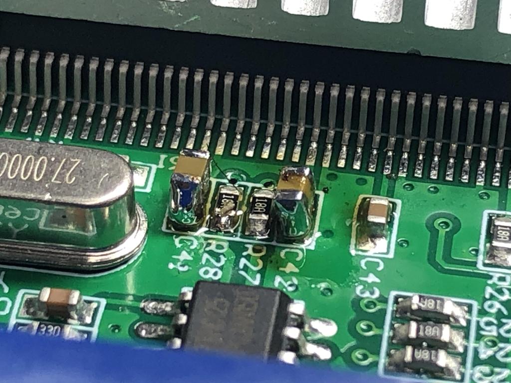
These are the caps we want to remove:
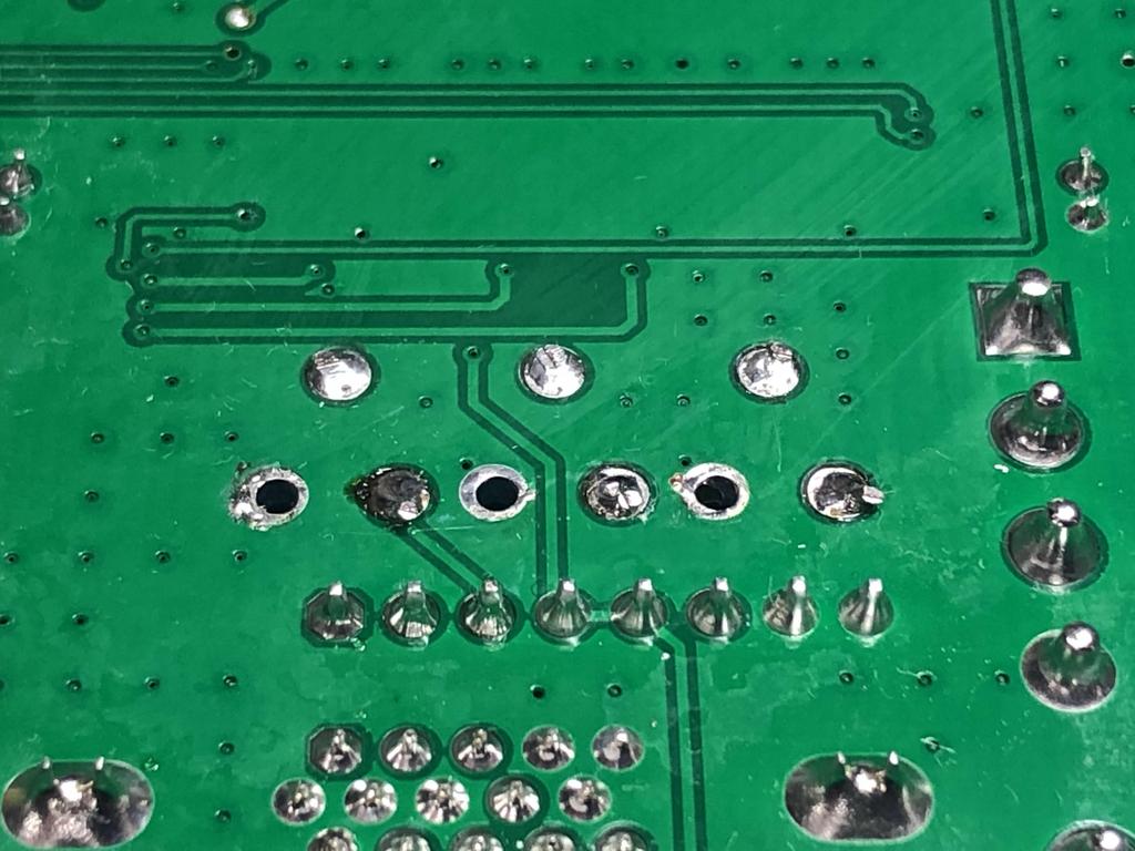
Using my desoldering gun, I desoldered the three legs of each pot underneath the board:
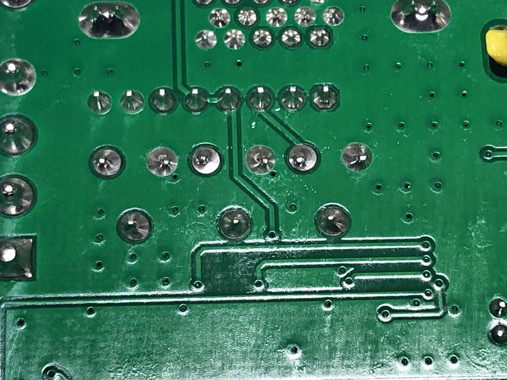
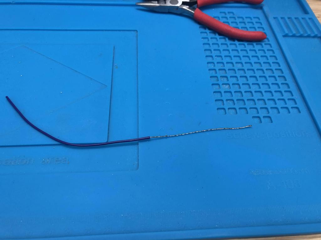
I used a piece of wire that I stripped and tinned, and then cut into three to bridge the connections where the pots were:
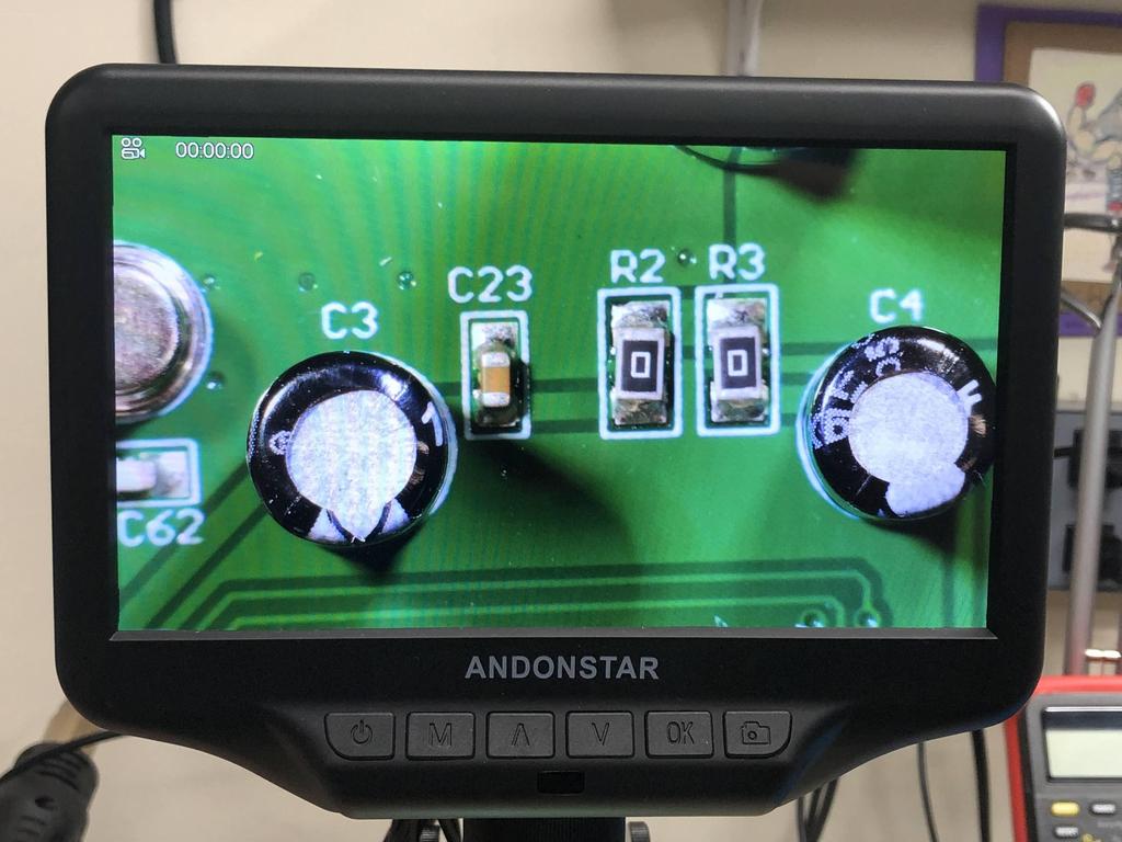
The next step is to stack some 10uF capacitors on top of existing ones to add more capacitance for power supply bypassing, which can reduce some forms of visible noise:
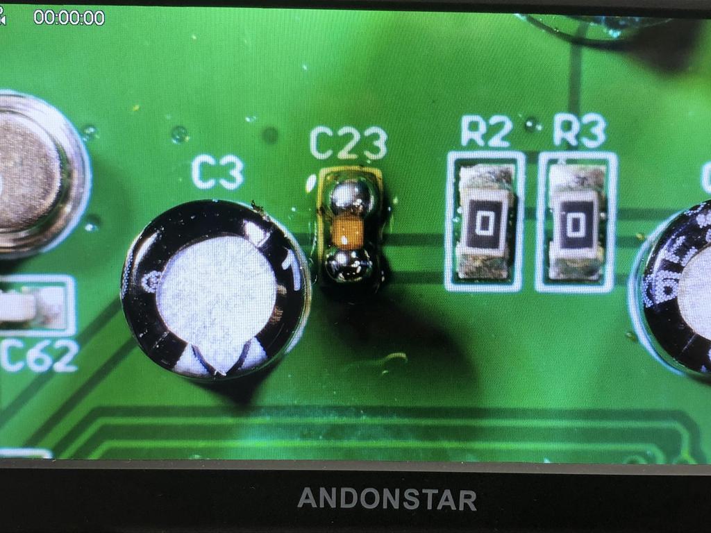
We start with C23:
Add flux and solder to both sides of the cap:
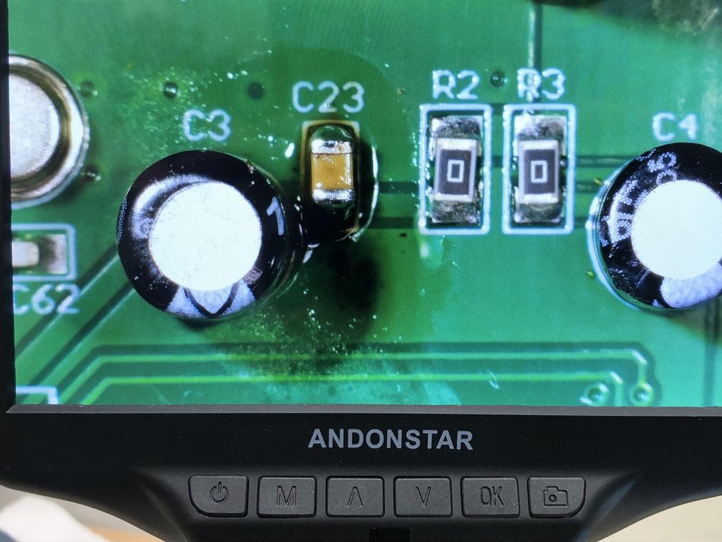
Then stack one of the 0805 10uF caps on top, and touch each side with the soldering iron:
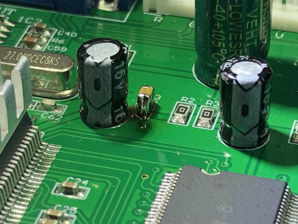
We do the same with C41 and C42:
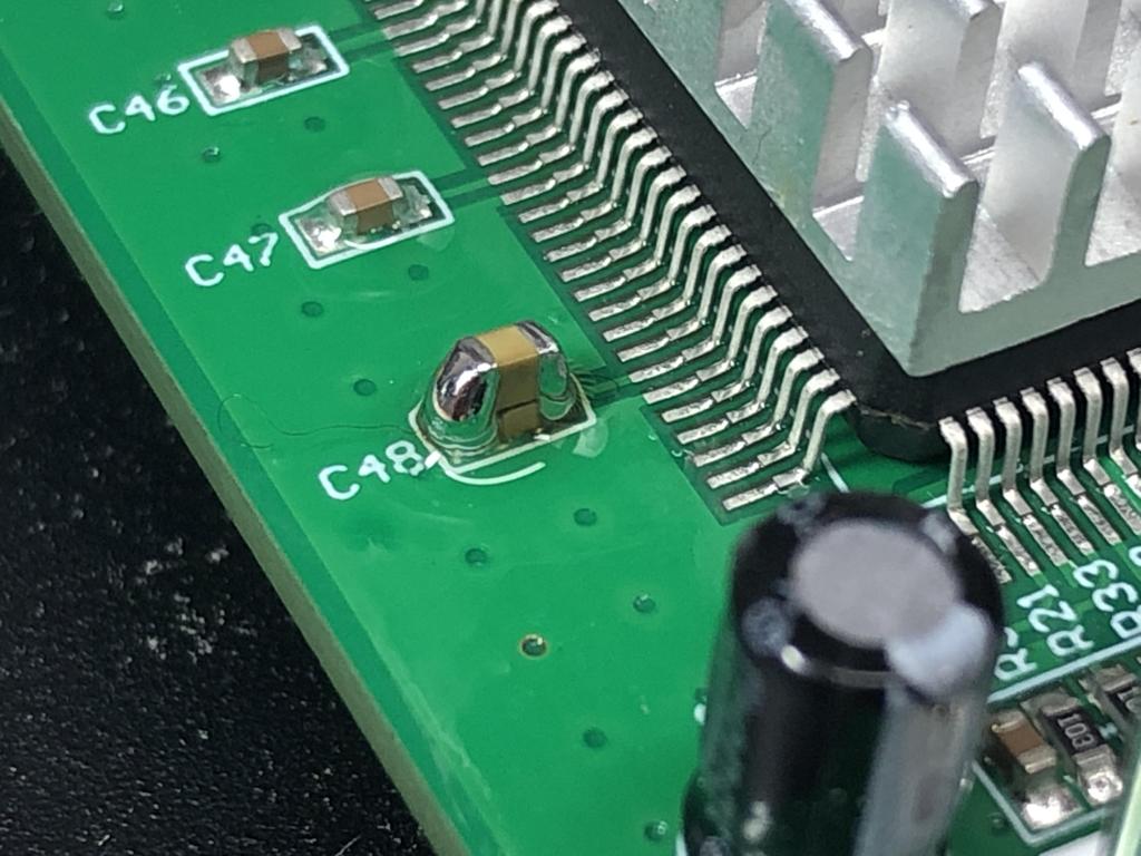
And C48:
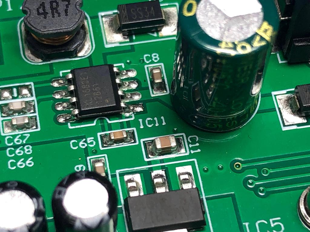
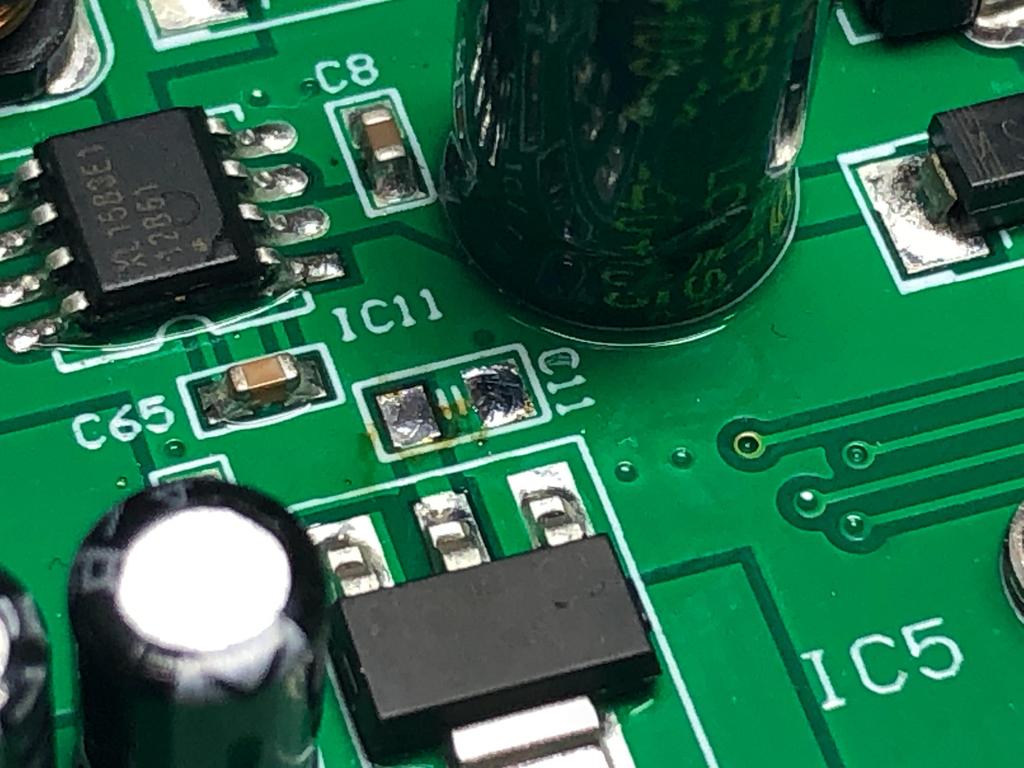
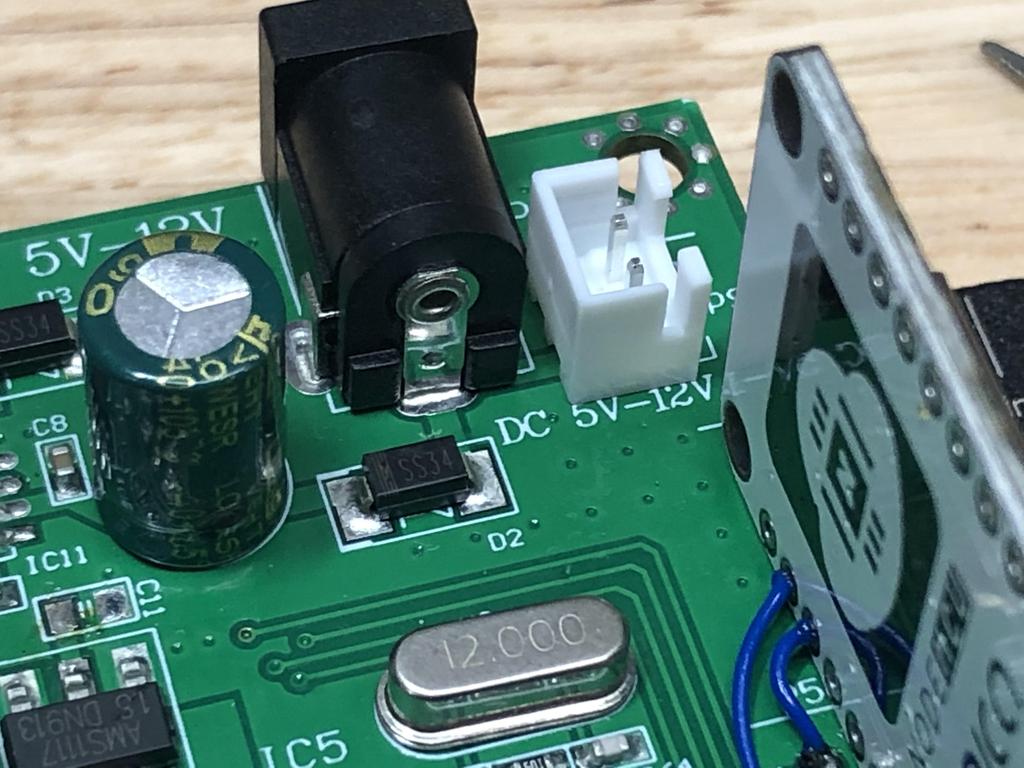
Next, we remove C11, which should help LDO oscillation problems with power supplies > 5V (though in this build, we really should only use a 5V power supply to avoid damaging the VGA to HDMI adapter):
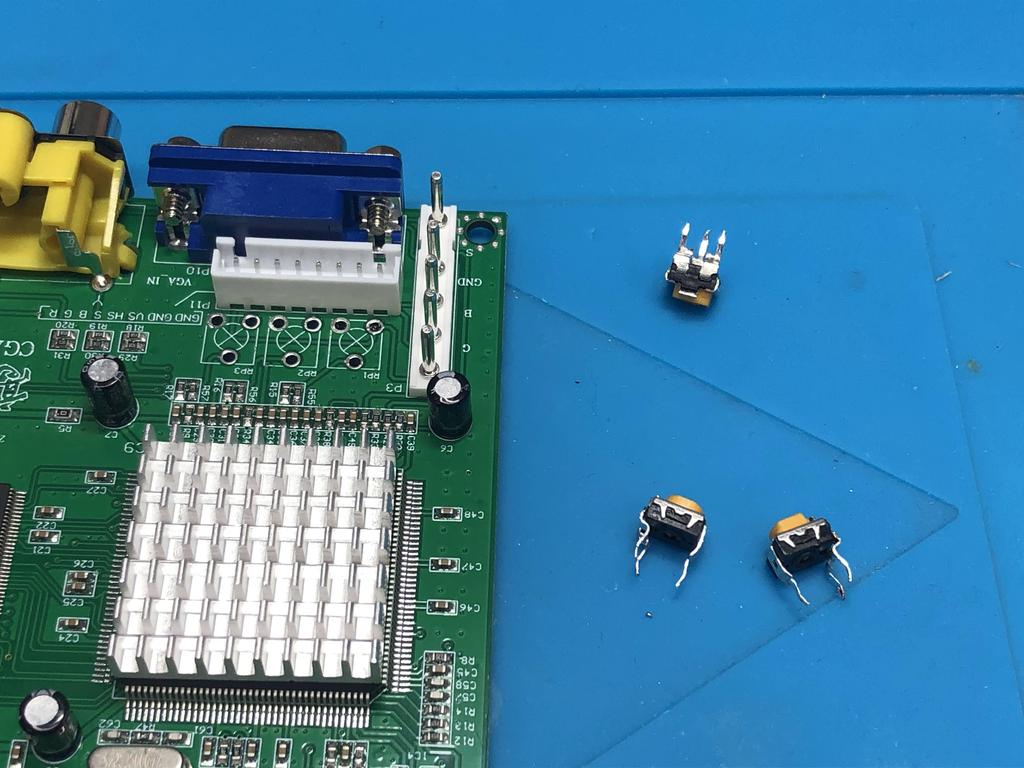
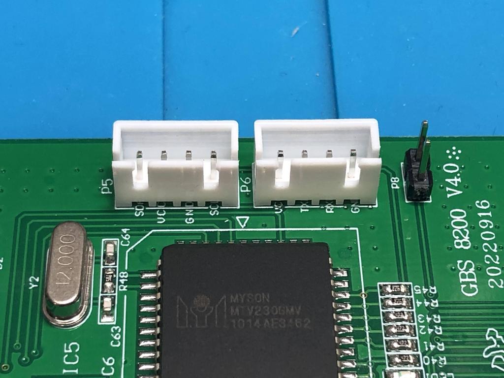
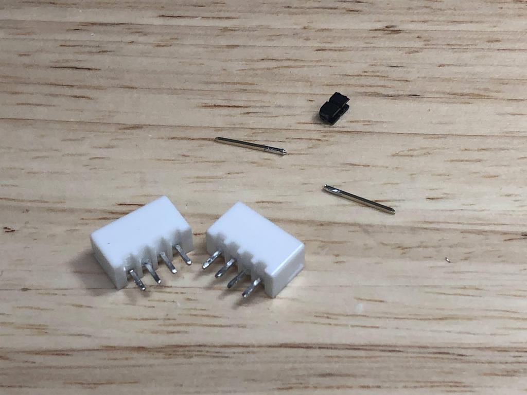
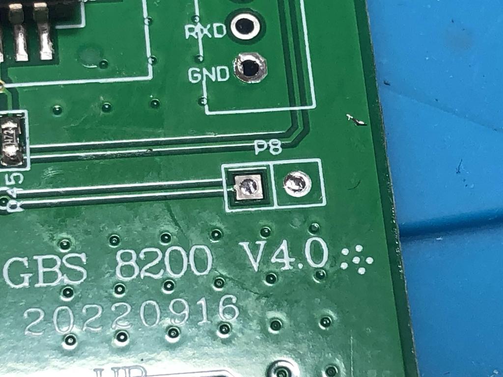
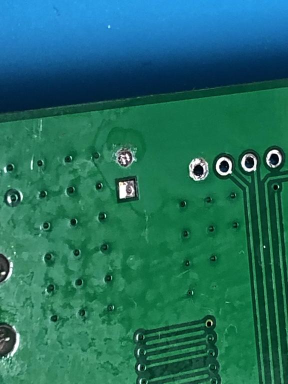
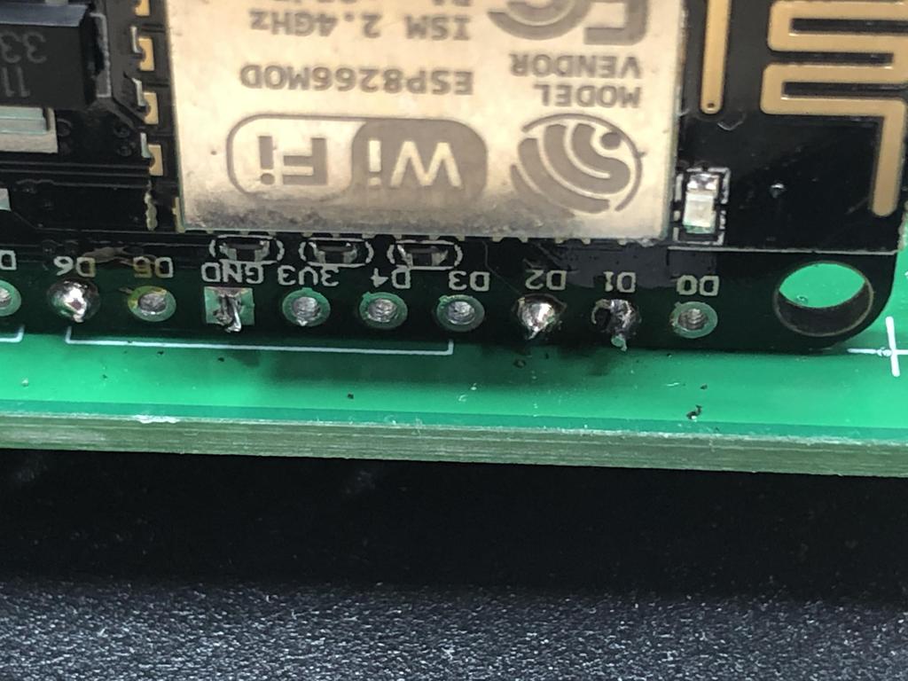
As we’ll be mounting the ESP8266 to the edge of the GBS board, we need to remove these connectors at P5, P6, and P8, which I did with my desoldering gun:
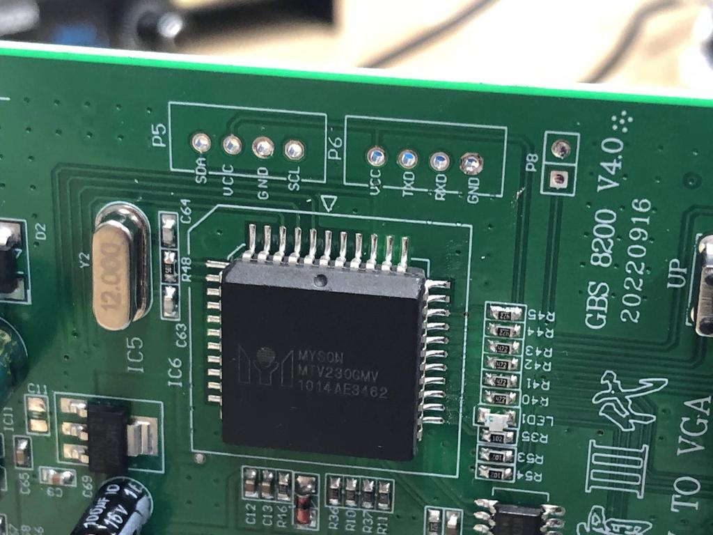
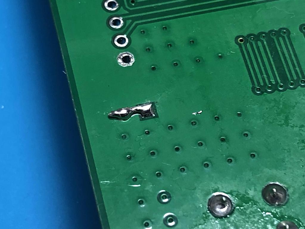
To allow the gbs-control to actually override the default GBS functionality, we need to bridge the programming port at P8. I did this by soldering a small wire between the two vias underneath the board. This ensures that it doesn’t get in the way of mounting the ESP8266 along that edge:
That’s it for the board prep.
ESP8266 Programming and Install #
Now we tackle the brains of the operation: the ESP8266. This device basically overrides the built-in firmware of the GBS8200, providing many features such as a web-based GUI that you can control from your phone or computer. The gbs-control firmware is written by ramapcsx2 (Robert Neumann) and is open source and available on GitHub.
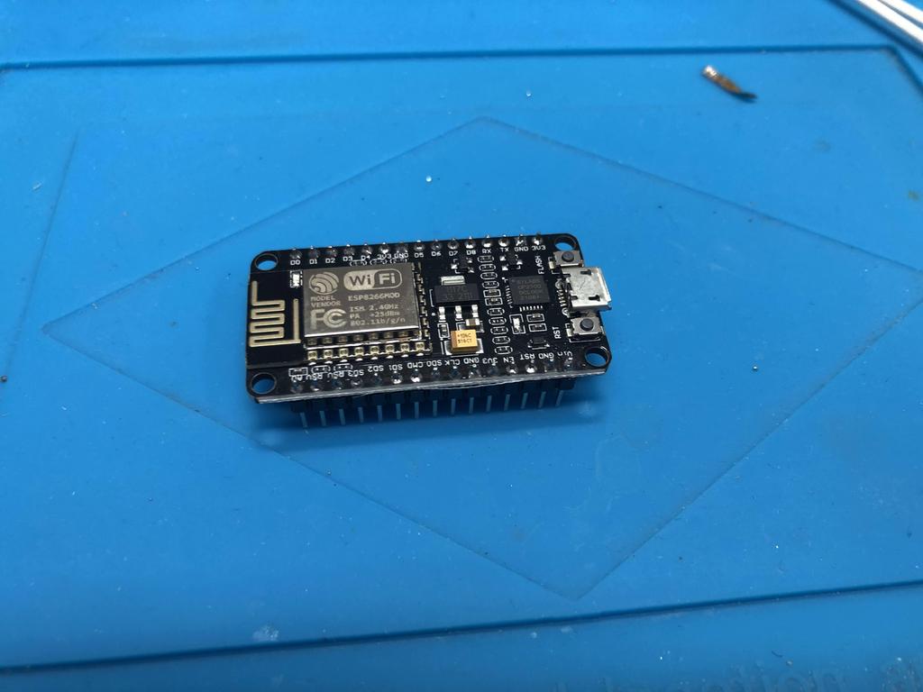
My ESP8266 came with pin headers installed, so first thing I did was desolder them:
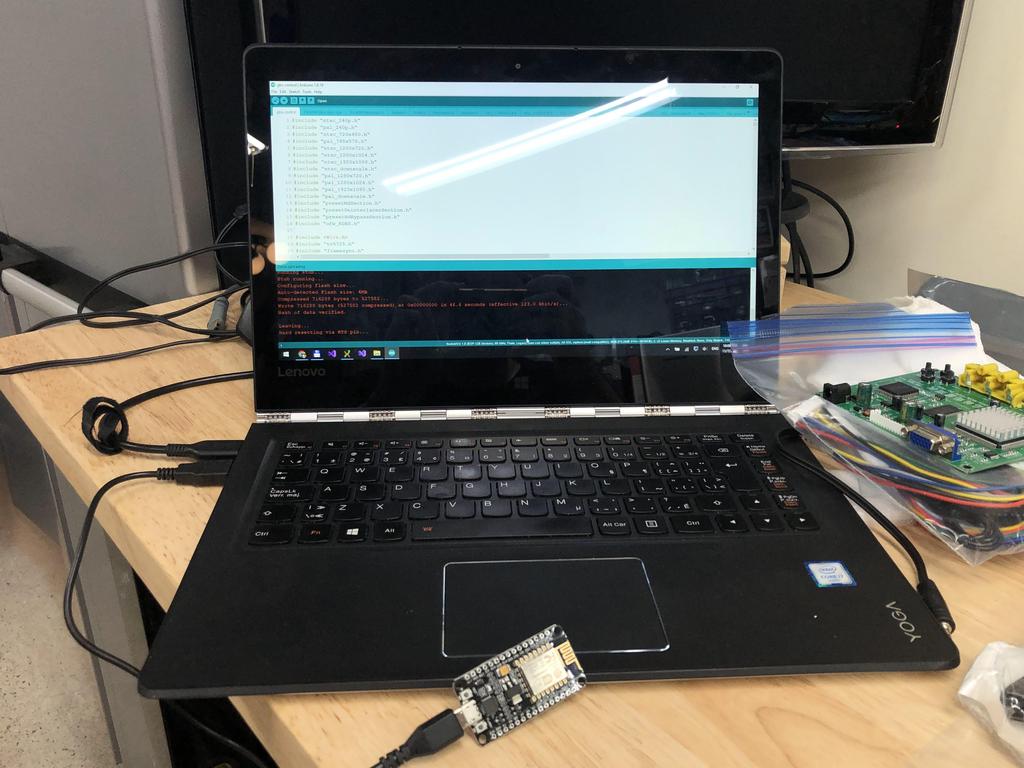
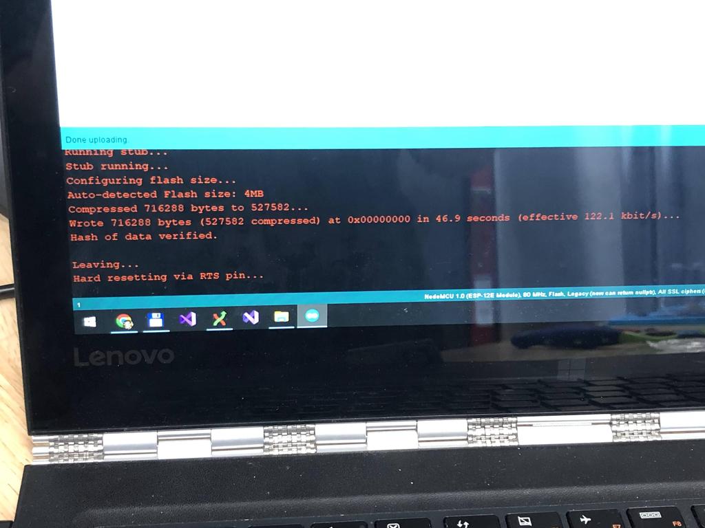
Then, I followed the detailed Software Setup steps to install the Arduino IDE, along with the ESP8266 support libraries, etc. Then I downloaded the gbs-control firmware and installed it onto the ESP8266 from my laptop:
At this point, while still connected to the PC, you should be able to test that the firmware is installed properly by searching for WiFi networks and looking for one named “gbscontrol”. You can connect to it, using the default password qqqqqqqq (that’s 8 q’s), then opening http://gbscontrol to access the control panel UI. If this works, you’re good! You can optionally configure the ESP8266 to connect to your home WiFi, which I recommended, as it allows you to easily control the system without disconnecting from your home network every time.
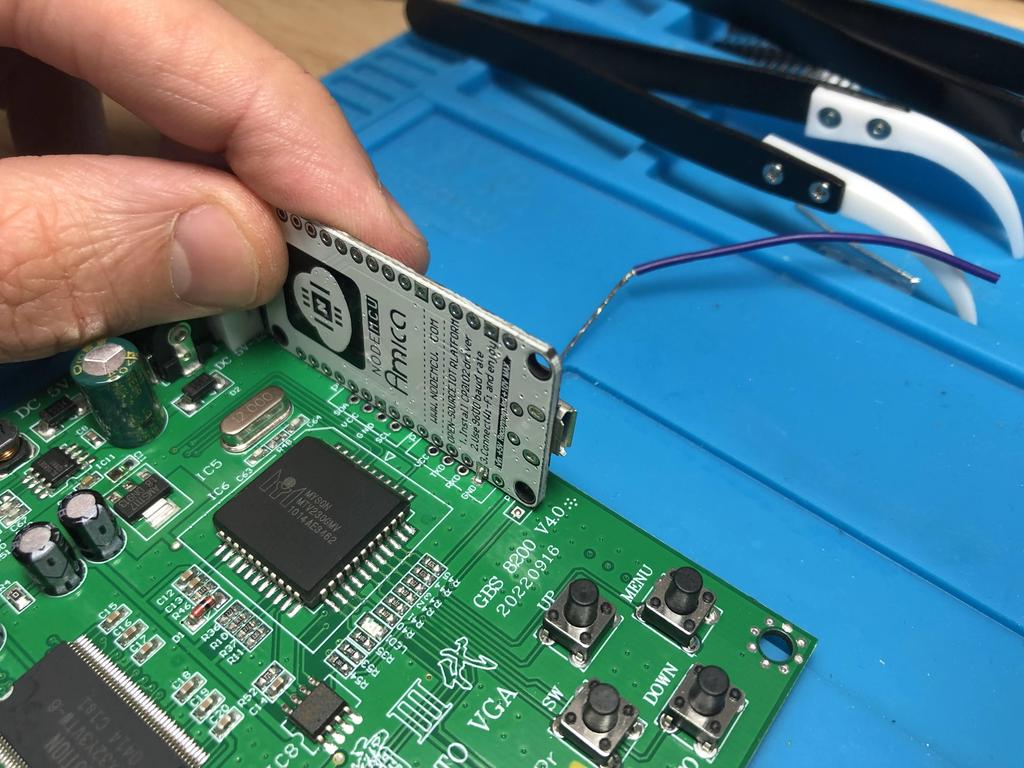
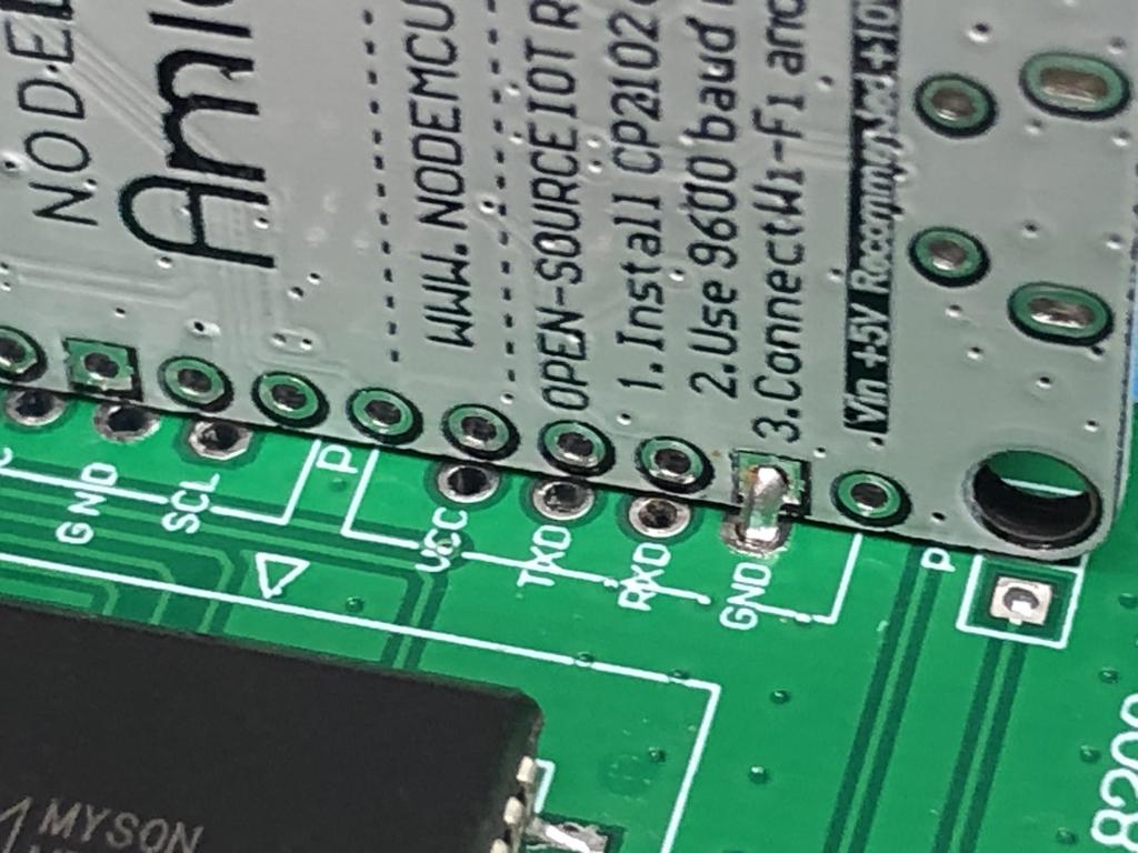
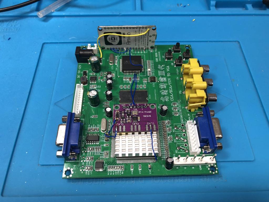
With the ESP8266 programmed, I proceeded to install it onto the GBS board using Voultar’s method - that is, installing it sideways along the edge of the board, lining up the GND vias:
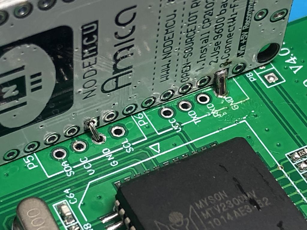
I stripped back some wire and tinned it, then threaded it through both GND vias of the ESP8266 and GBS board:
Holding the ESP8266 in place, I added more solder to the bit of wire between the two to make a strong connection, and to make it hold in place:
There is a second GND via on the board that also lines up with the ESP8266, so I did the same thing with that:
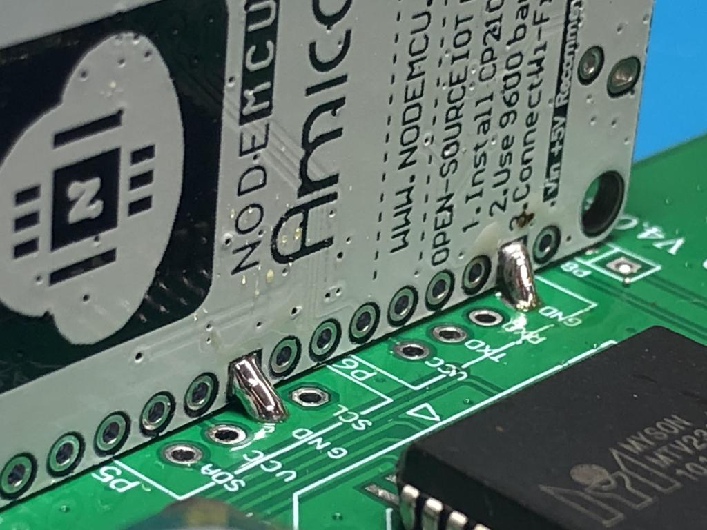
Once both GNDs are connected, the ESP8266 shouldn’t move:
Next, we have a few connections to make between the ESP8266 and the GBS.
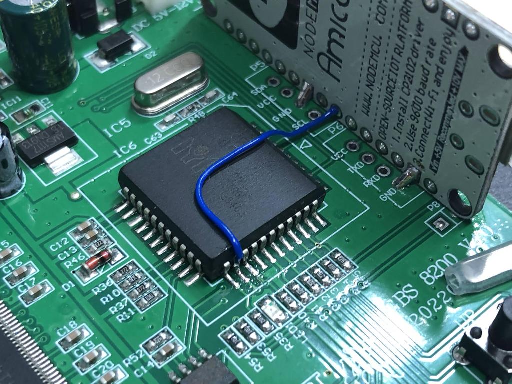
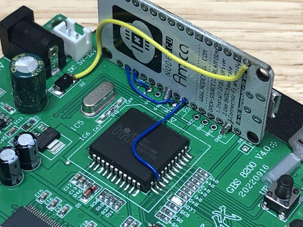
First, I connected the “Debug Pin” from the controller IC to “D6” on the ESP8266, which allows the gbs-control to enable automatic image positioning and timing adjustments:
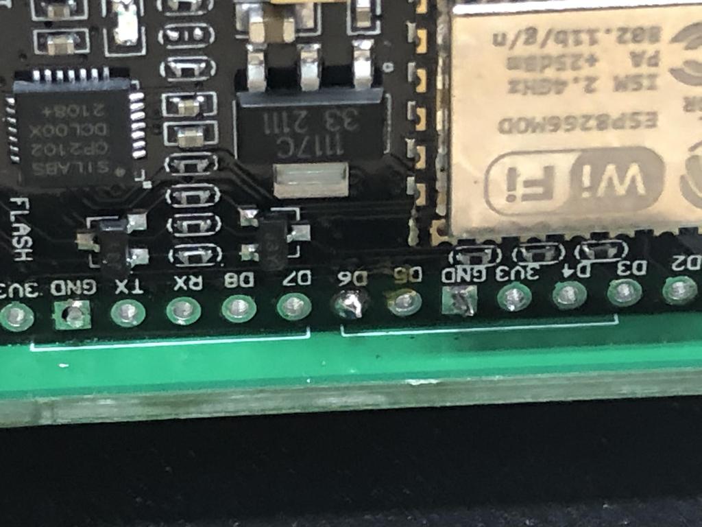
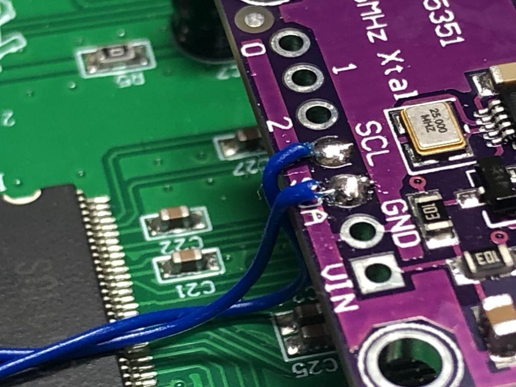
Next, I connected the two I2C bus wires SCL to D1, and SDA to D2:
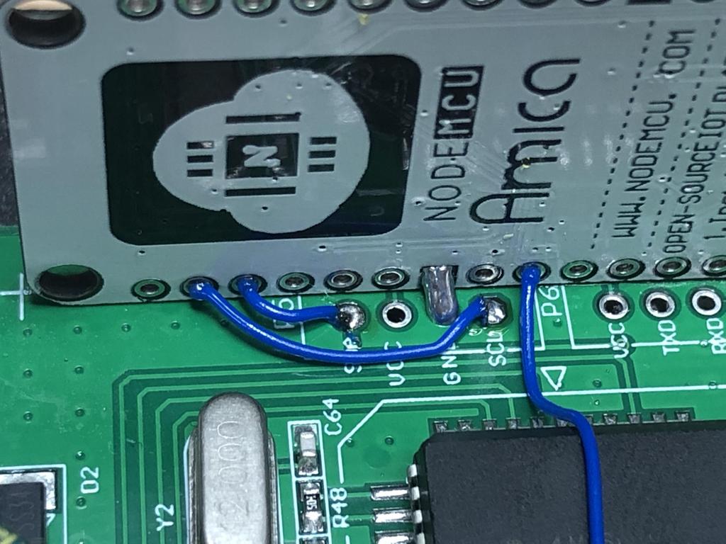
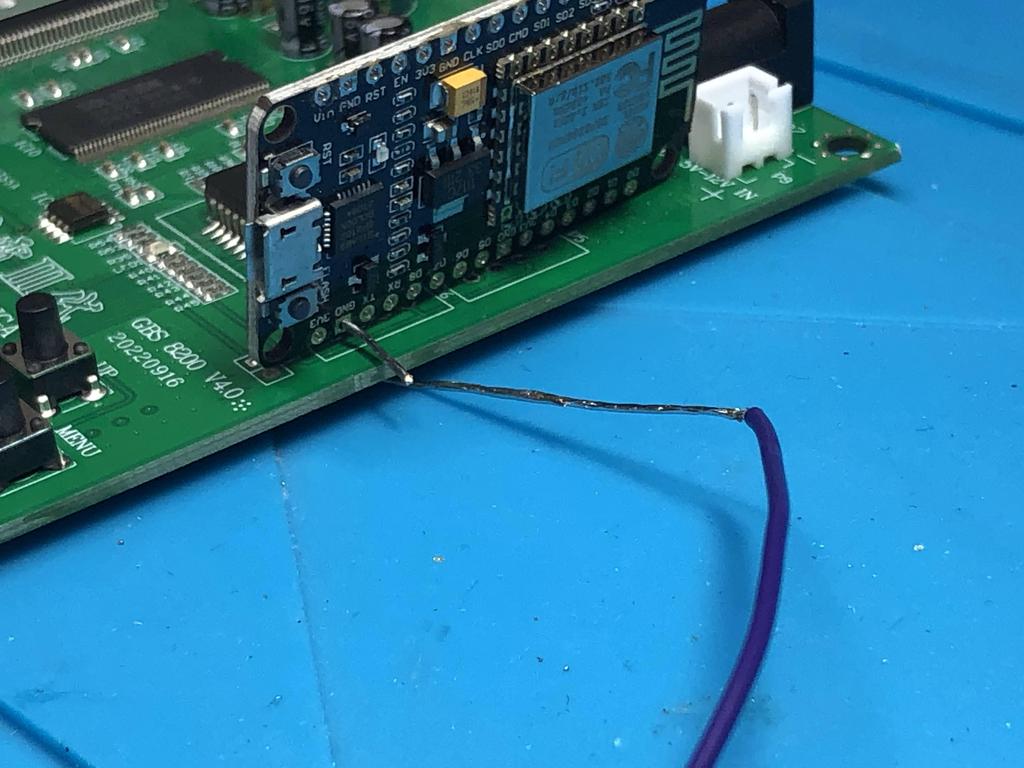
Finally, I connected a wire from the right side of D2 to Vin, which will supply 5V to the board once powered:
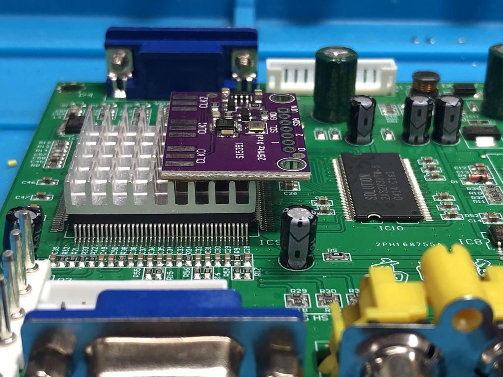
Clock Generator Install #
The Si5351 clock generator board is optional, but recommended to allow the gbs-control to output precise frequencies:
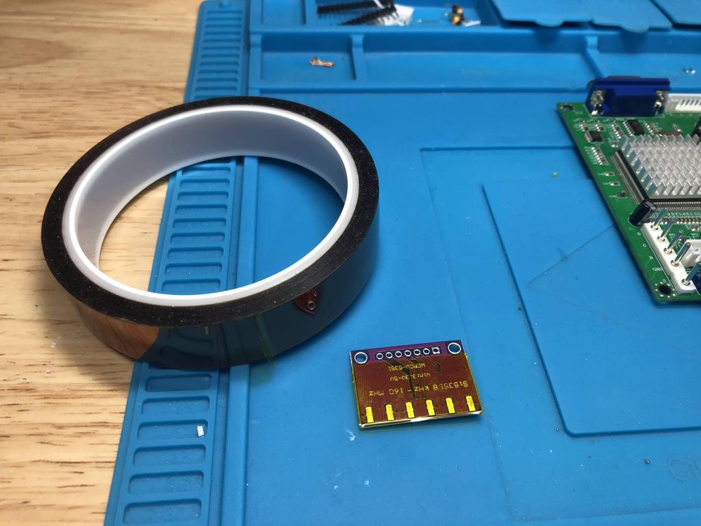
First, I stuck some kapton tape to the underside, making sure to keep the vias uncovered:
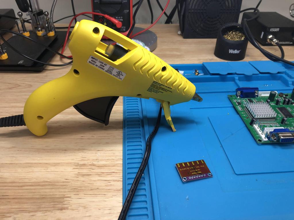
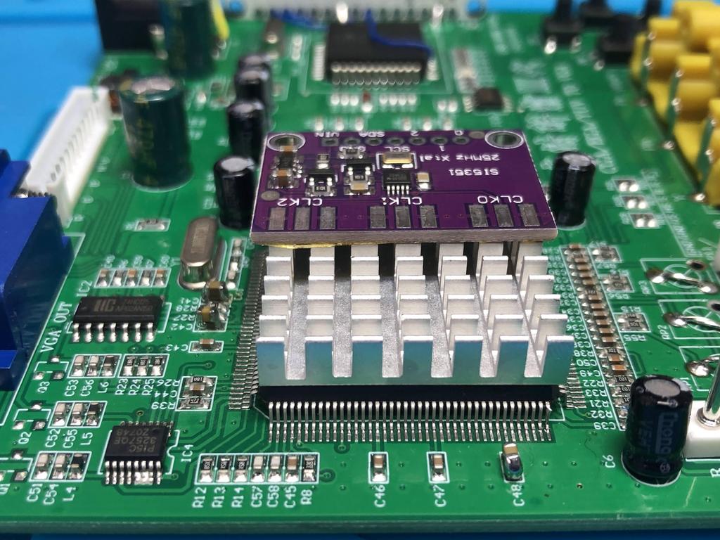
Using hot glue, I then stuck that kapton-covered part onto the edge of the heat sink-covered TrueView chip:
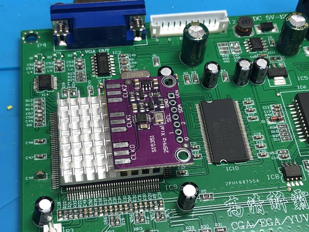
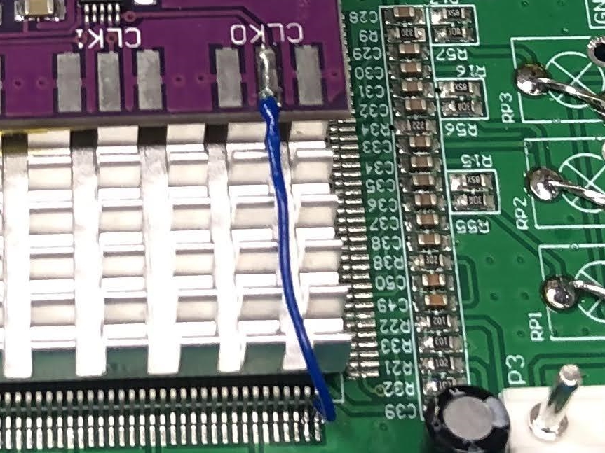
Now to connect the clock generator, I started by soldering a wire from pin 40 of the TrueView to the center CLK0 pad:
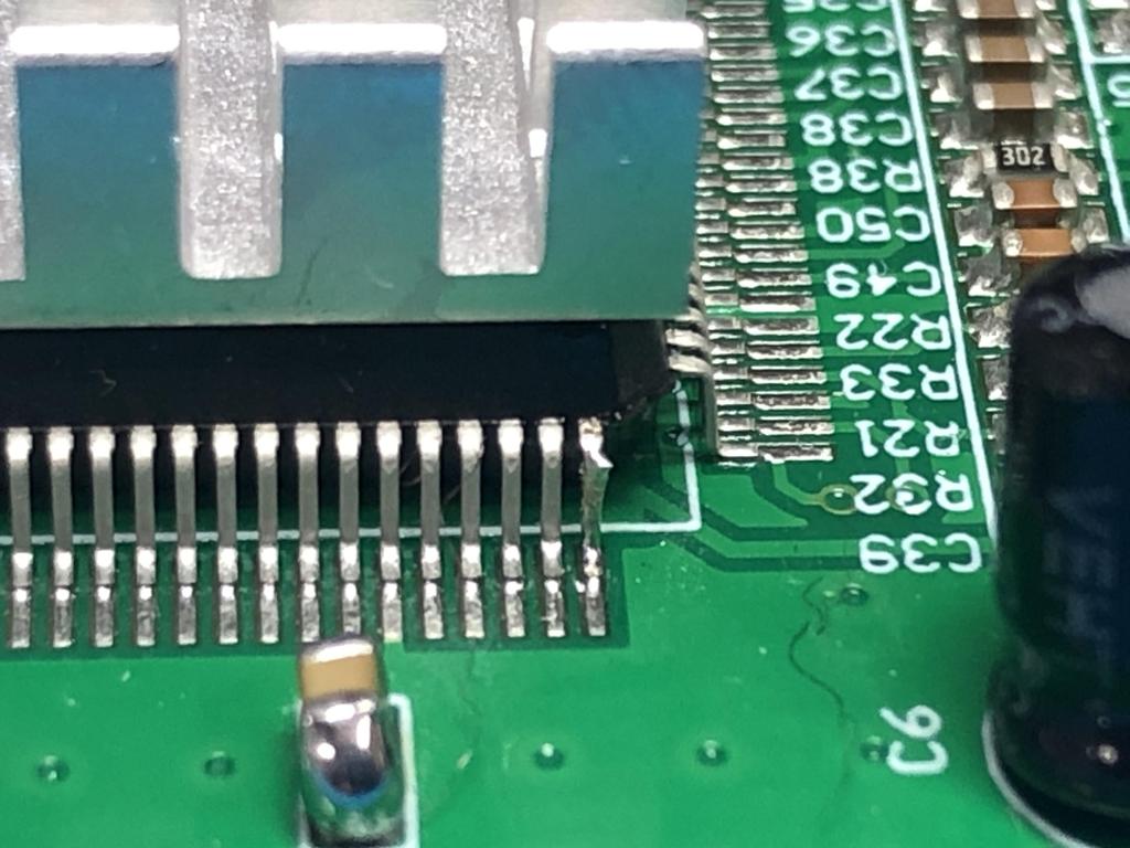
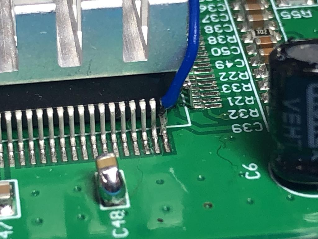
Next, I connected the CLK2 edge pad to C41 for the ground connection:
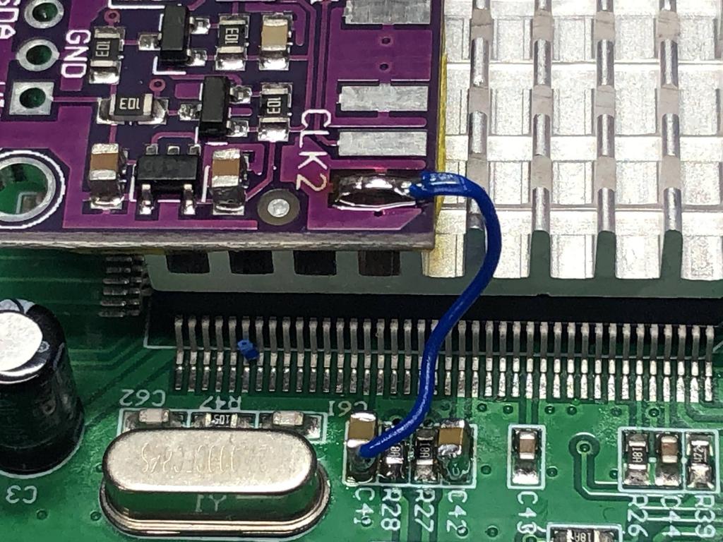
Note that the official instructions suggest connecting the CLK2 pad to ground sides of C47 or C48; however, C41 is closer and works just as well.
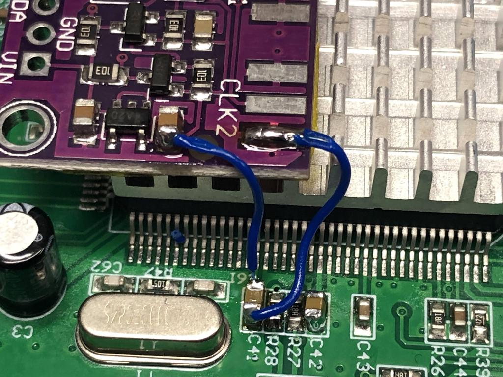
To power the clock generator, I soldered a wire from the positive side of C41 to the unlabelled capacitor near the edge:
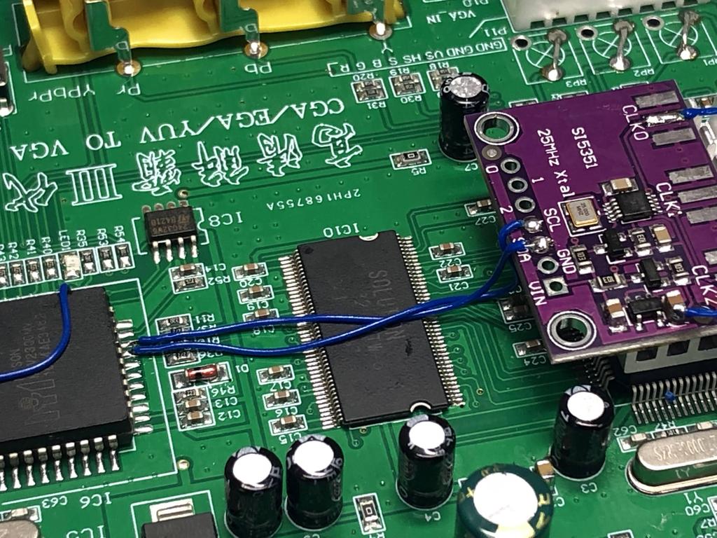
Finally, we need to connect two wires between the MTV230 chip and the TrueView chip: from pin 25 to SCL, and from pin 26 to SDA:
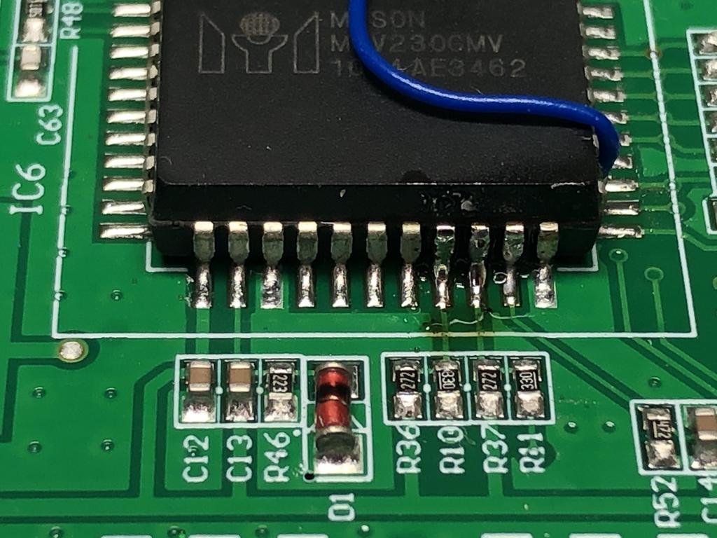
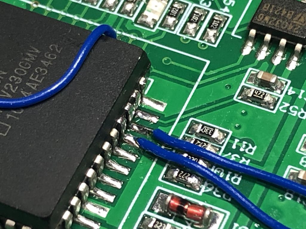
Note that the wires actually cross over each other:
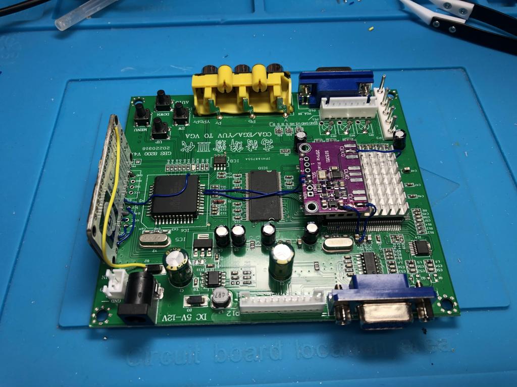
At this point, I’m done with all the soldering on the GBS itself:
VGA to HDMI Adapter #
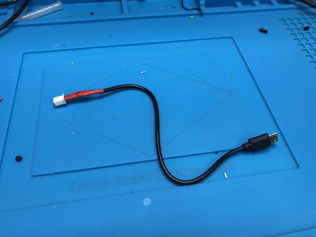
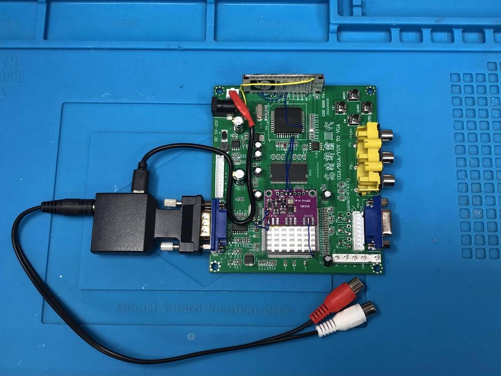
The VGA to HDMI adapter that we got needs to be powered by 5V, and comes with a short micro-USB power cable for just that reason. Instead of hooking it up to an external source, we’ll modify the cable so that we can connect it directly to the GBS board. We do this by using the red and black power connector that comes with the board itself:
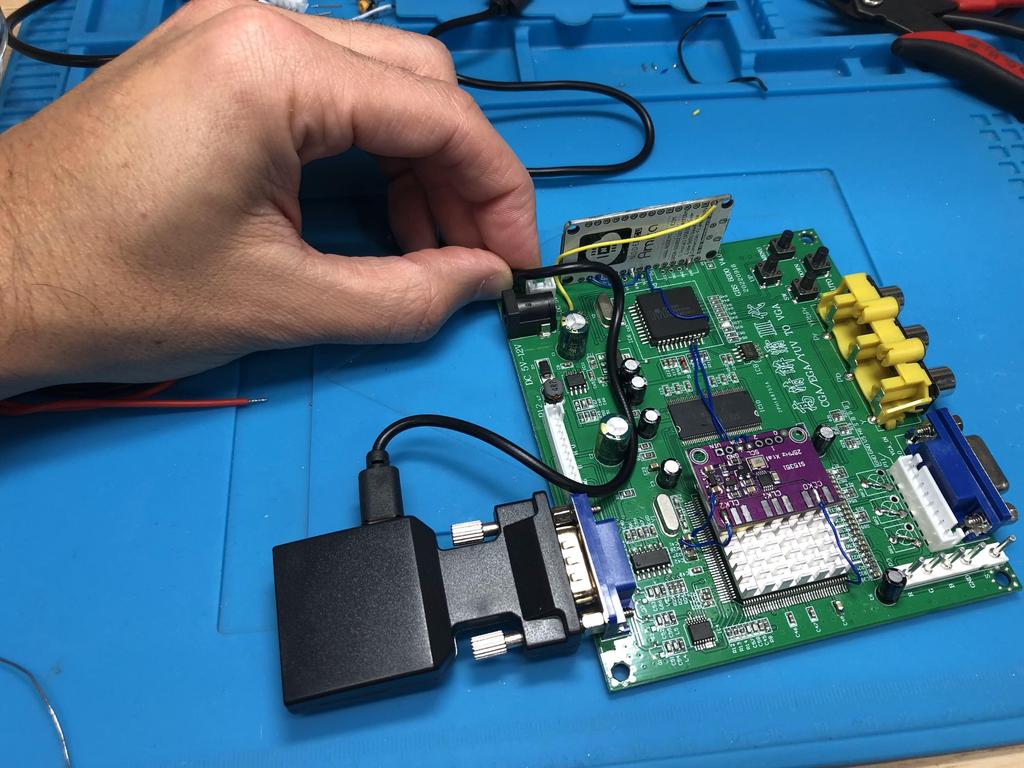
I hooked up the adapter to the VGA output port, then measured out the USB cable so that the other end lines up with the 2-pronged power jack:
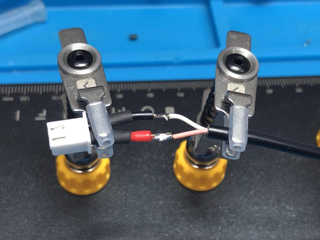
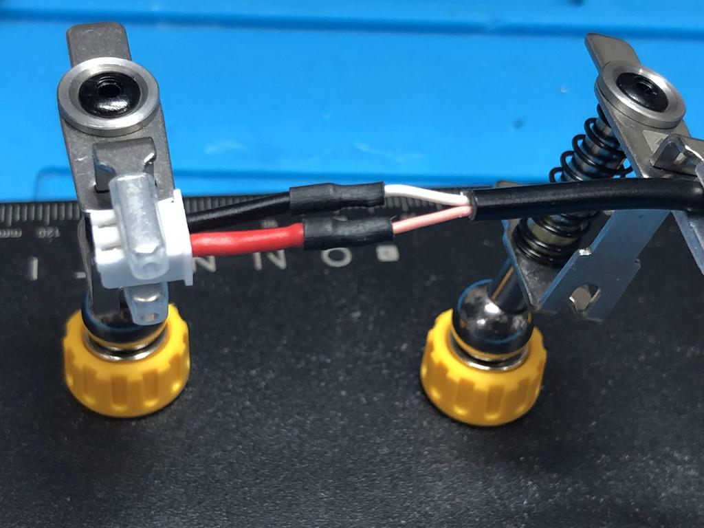
I cut the cable there, stripped it back, then stripped and tinned the two wires inside:
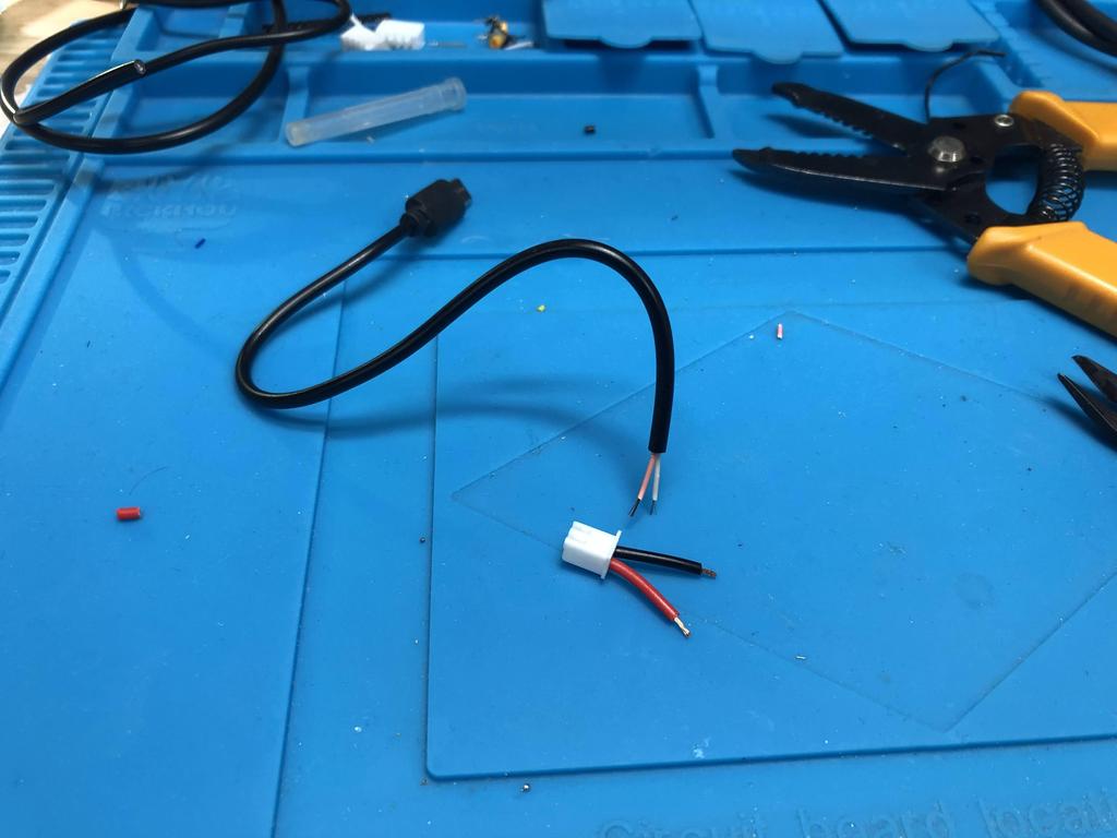
I used my multimeter to make sure I knew which wire was GND and which was 5V, then proceeded to solder the cable to GBS power connector (black is ground, red is 5V):
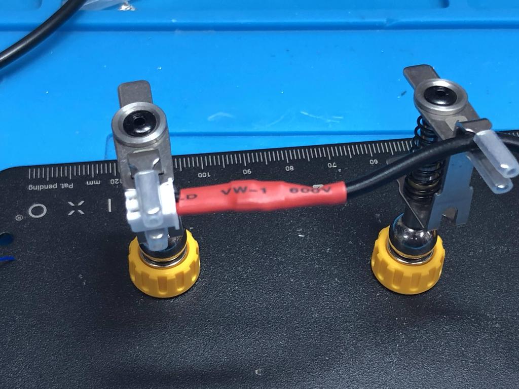
And with that, I can now easily power the adapter from the board itself:
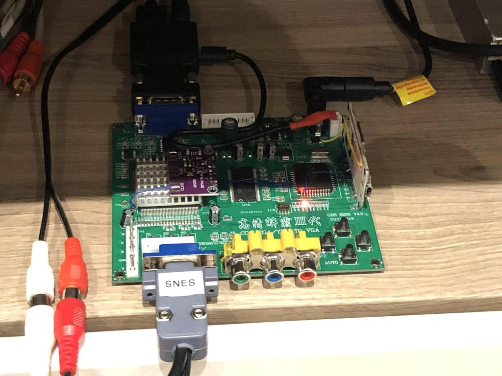
Testing #
I hooked up my SNES to the gbs-control, and hooked up the HDMI output to my TV, and played some Super Metroid:
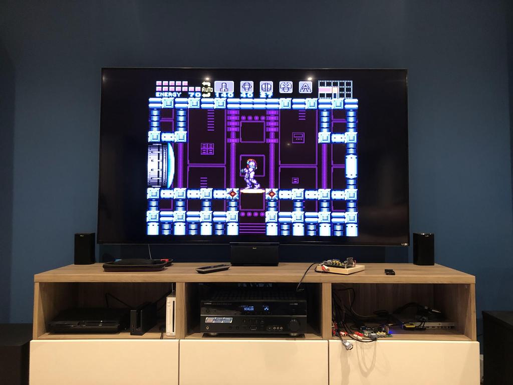
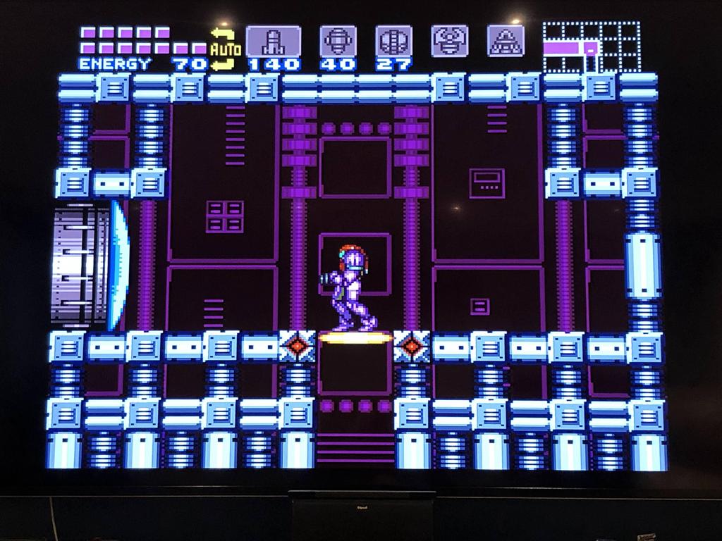
The picture quality is really quite good!
Thoughts #
Of course, my opinion on the gbs-control hasn’t changed since the first one I build. It’s an excellent scaler, especially for the price!
If this post helps you to build one of your own, then please let me know!
Also check out my posts about how I made gbs-control cases here and here.