gbs-control Case for HDMI Out
A little while ago, I built a gbs-control to up-scale up video signals from my old consoles to my LCD TV. I eventually built a second one to use as a down-scaler/transcoder to my CRT, and made a custom cable for it. The final missing touch for both these projects was a nice case. In this first post, I’ll go over how I designed, printed, and assembled a case for the HDMI out gbs-control. My next post will cover the second case.
Design #
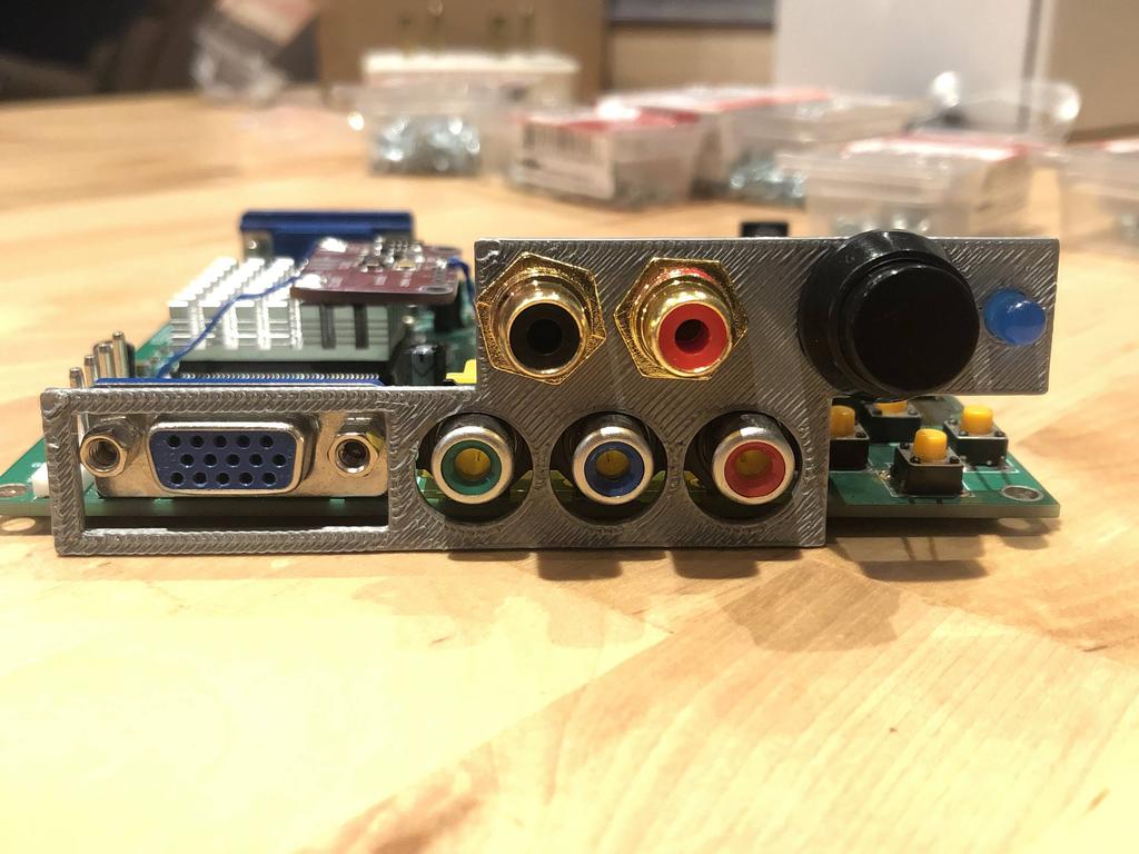
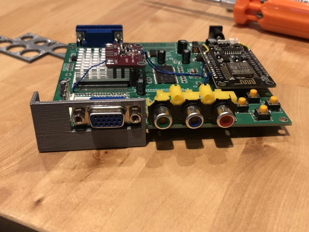
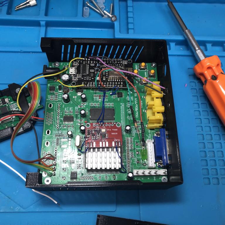
My first gbs-control is the one I use to up-scale RGB and YPbPr input signals to HDMI out:
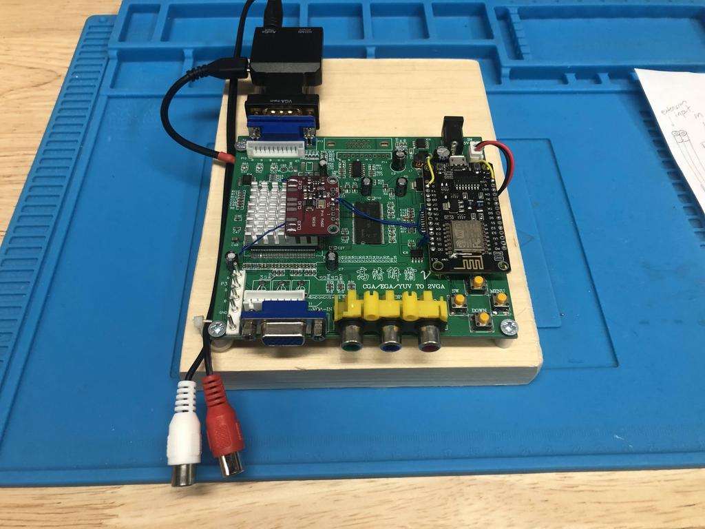
As you can see, the PCB is screwed into a piece of wood I cut, and there’s a VGA-to-HDMI adapter hanging off the back, along with female RCA cables for stereo audio input that connect to the same adapter.
My goals for this case were:
-
Get rid of the ugly adapter hanging out the back. Inspired by this case design, I’d incorporate the adapter inside the case, and expose only the HDMI port out the back.
-
Add a reset button to the front. Sometimes the gbs-control gets in a weird state when disconnecting and connecting devices, and I’ve found it useful to be able to press the reset button on the NodeMCU board. Since this will be tucked in the case, I decided to expose it at the front of the case.
-
Display a status LED on the front. The gbs-control source code turns the NodeMCU on-board LED on to indicate when a proper signal has been detected, and off otherwise. I’ve found this useful as well, and similar to the reset button, decided to expose it on the front of the case since the NodeMCU would no longer be visible.
Case #
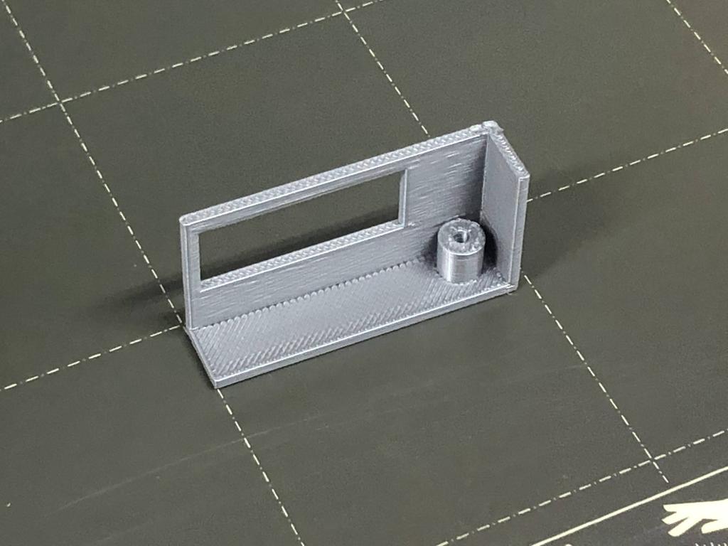
After spending many hours (mostly learning) Fusion 360, here’s what I came up with for the case itself:
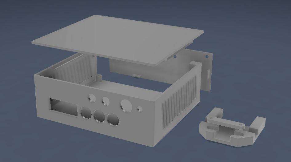
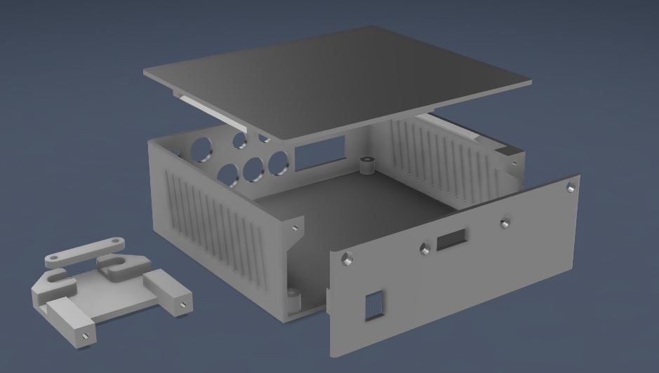
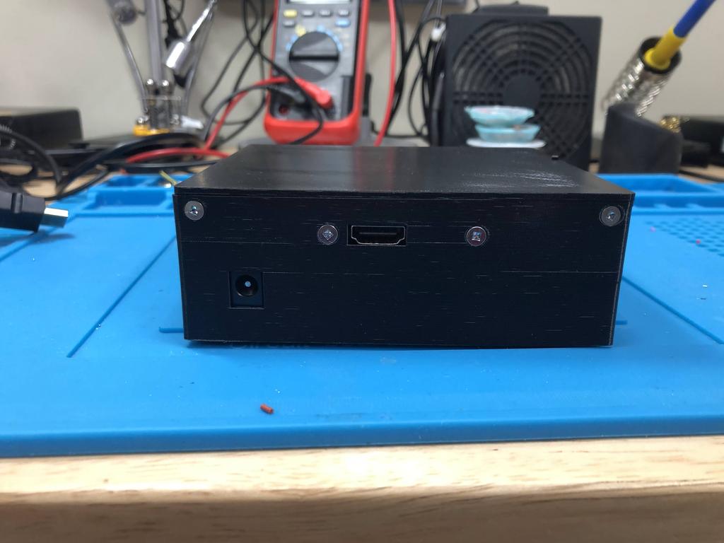
You can see that the front panel has holes for the gbs board’s inputs, along with a top row of holes for audio inputs, reset button, and the status LED. On the side is the HDMI “cradle”, used to hold the VGA-to-HDMI PCB in place against the back panel.
Note how the back panel is a separate piece. I decided to do this because I knew I’d want a different back panel for my second gbs-control. As it turned out, it also made it much easier to slide in the gbs board into the case.
Reset and Status LED #
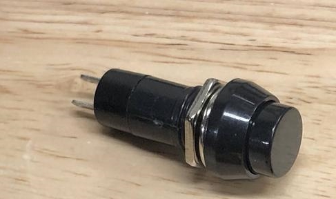
To be able to reset the gbs-control from the front panel, I bought a momentary switch:
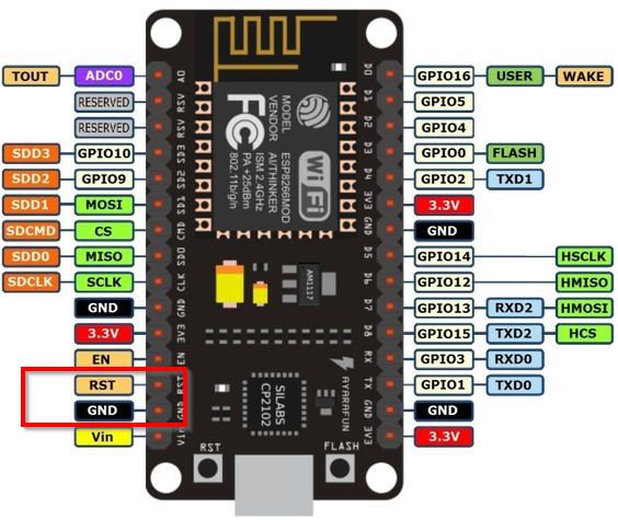
Resetting the NodeMCU is done very simply by connecting the RST pin to ground:
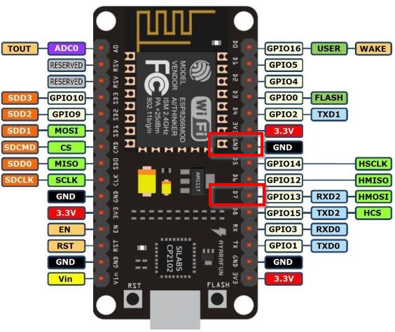
For the status LED, it’s slightly more complicated. The NodeMCU’s LED state is connected to D0 (GPIO16), but it’s an “active low” signal, meaning that when the LED is on, D0 is low (GND), and when the LED is off, D1 is high (Vin). This is the opposite of what we need for our external LED. One solution would be to build an inverter circuit, or to use an inverter IC.
Instead, I decided to fix it in software by modifying the gbs-control code to output the non-inverted status on an unused pin, like D7, which is exactly what I did (you can see my changes here). The crux of the change was to modify the LEDON AND LEDOFF macros to also write the opposite level to D7:
#define LEDON                         \
    pinMode(LED_BUILTIN, OUTPUT);     \
    digitalWrite(LED_BUILTIN, LOW);   \
    pinMode(D7, OUTPUT);    /* NEW */ \
    digitalWrite(D7, HIGH); /* NEW */
#define LEDOFF                        \
    digitalWrite(LED_BUILTIN, HIGH);  \
    pinMode(LED_BUILTIN, INPUT);      \
    digitalWrite(D7, LOW); /* NEW */  \
    pinMode(D7, INPUT)     /* NEW */
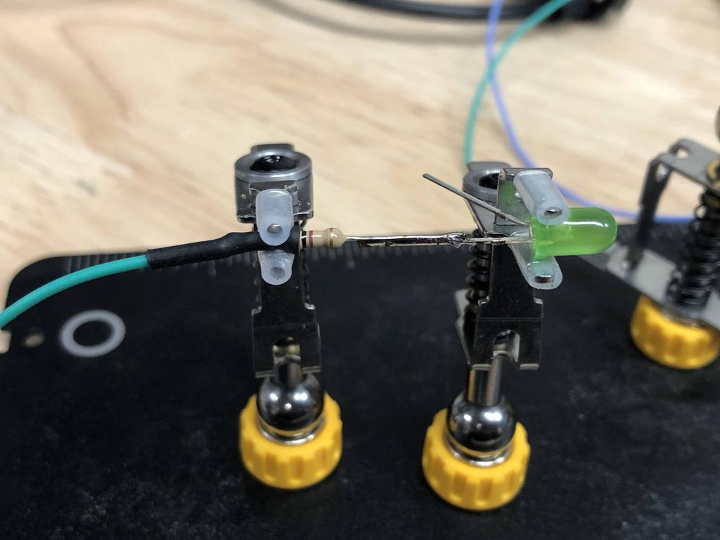
So now, I could simply wire up a LED with one end connected to D7 (with a resistor in series), and the other to ground:
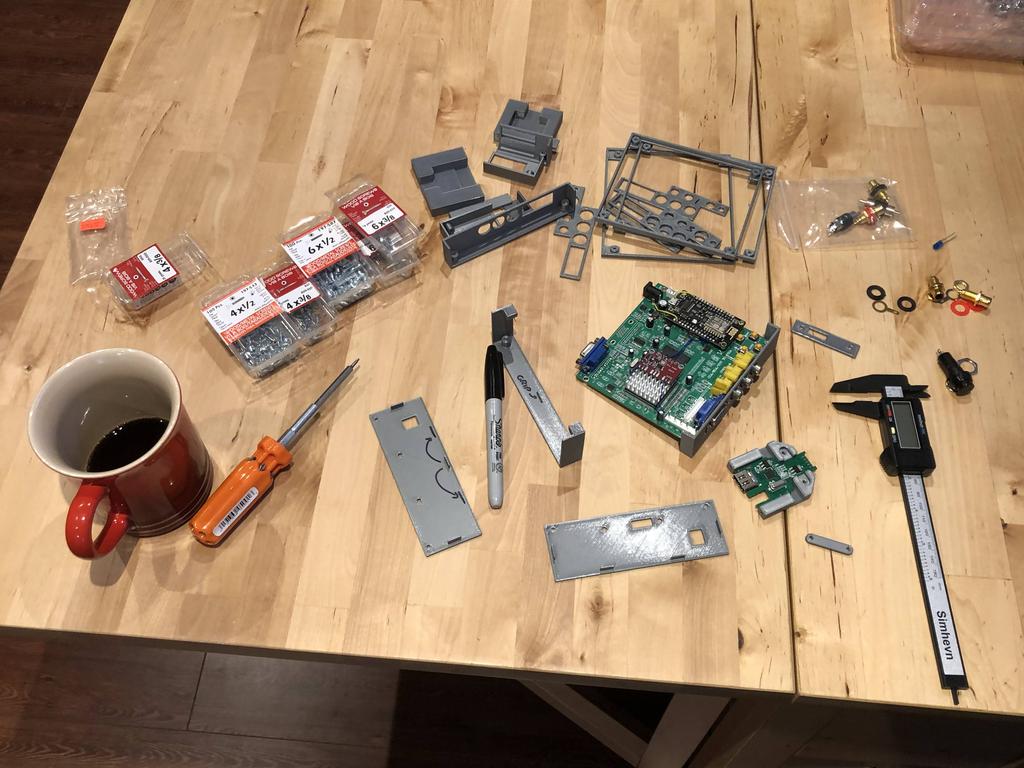
Parts #
Here are all the parts I needed to build this:
- A fully assembled gbs-control with the Node MCU positioned along the edge - see my post here.
- VGA to HDMI adapter
- A green LED
- 100 ohm throughole resistor for the LED
- #4 x 3/8” wood screws (846-020) - 8x total: 4 to attach the GBS to the case, 2 to attach the HDMI cradle clamp, and 2 to attach the back plate to the case.
- #4 x 1/2” wood screws (197-543) - 2x to attach the HDMI cradle to the back plate
- Momentary button - the “hole diameter” must be 10mm. The ones I bought were from a local store, but I’ve linked one on AliExpress that I think should work.
- 2x RCA female socket connectors - the “hole diameter” should be 5.6mm. The ones I used in this post are actually larger, but I’ve updated my design to fit the more commonly available connectors from AliExpress that I’ve linked here.
- 4x rubber feet to stick underneath the case
- 3D printed case
The Build #
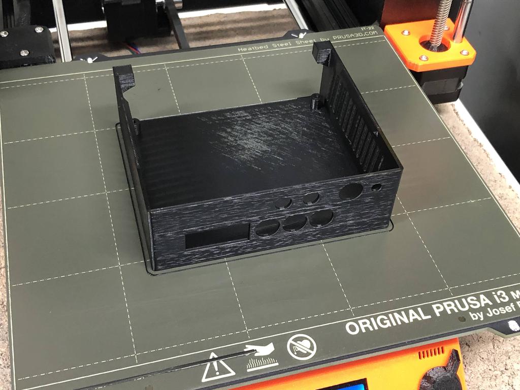
As a novice to 3D printing and designing, I spent a fair bit of time iterating and printing tests to make sure everything fit:

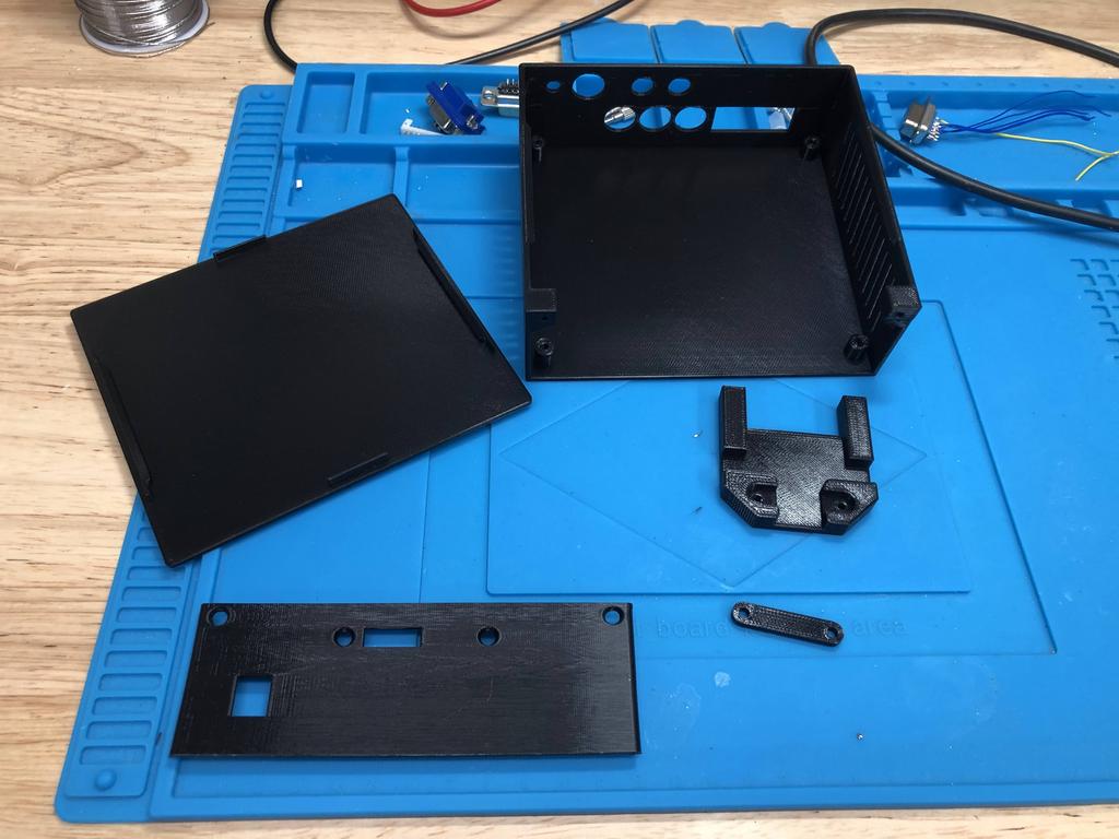
Finally, with everything ironed out, I printed out the pieces for the case:
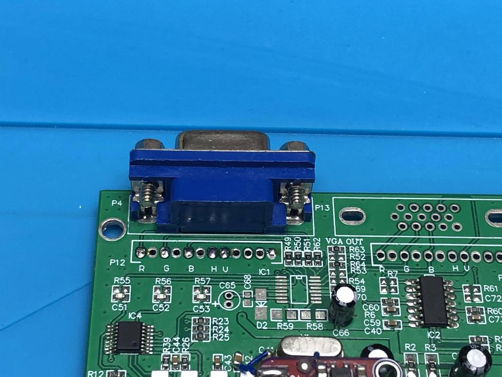
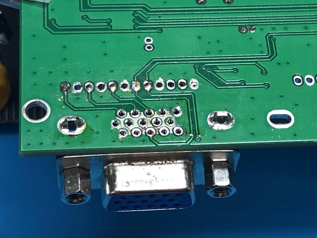
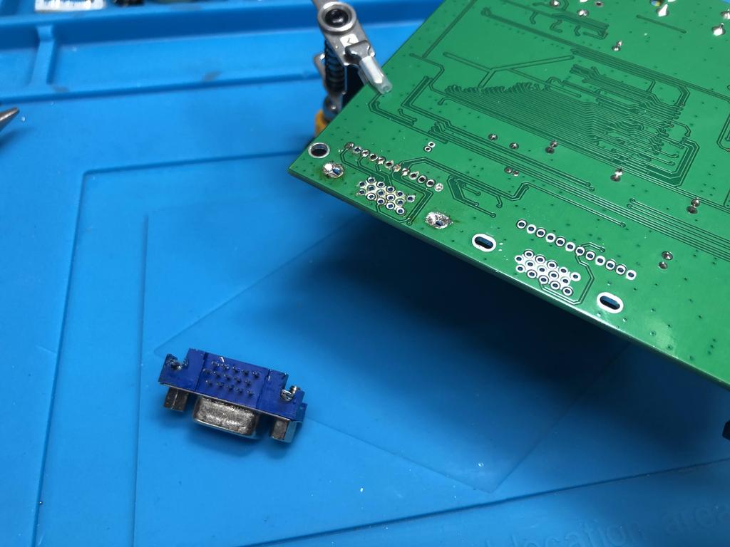
With the case printed, it was time to prep the gbs board. First I desoldered the VGA output connector off the back of the board:
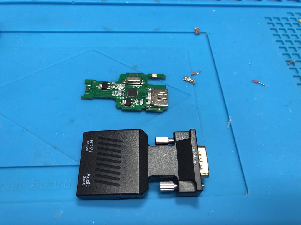
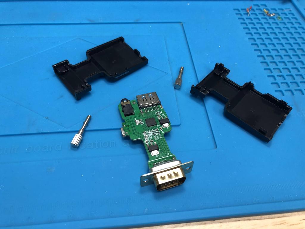
Next up was getting the VGA-to-HDMI adapter PCB out of its case, and removing a few components off of it:
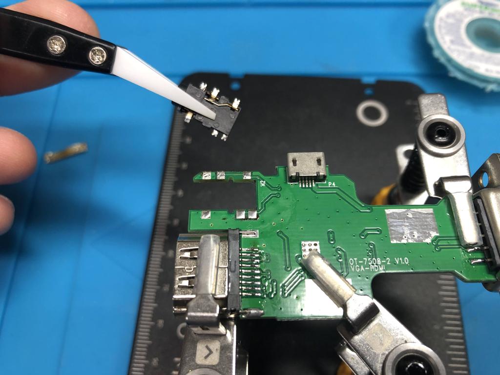
Using a hot air rework station, I carefully removed the audio input jack:
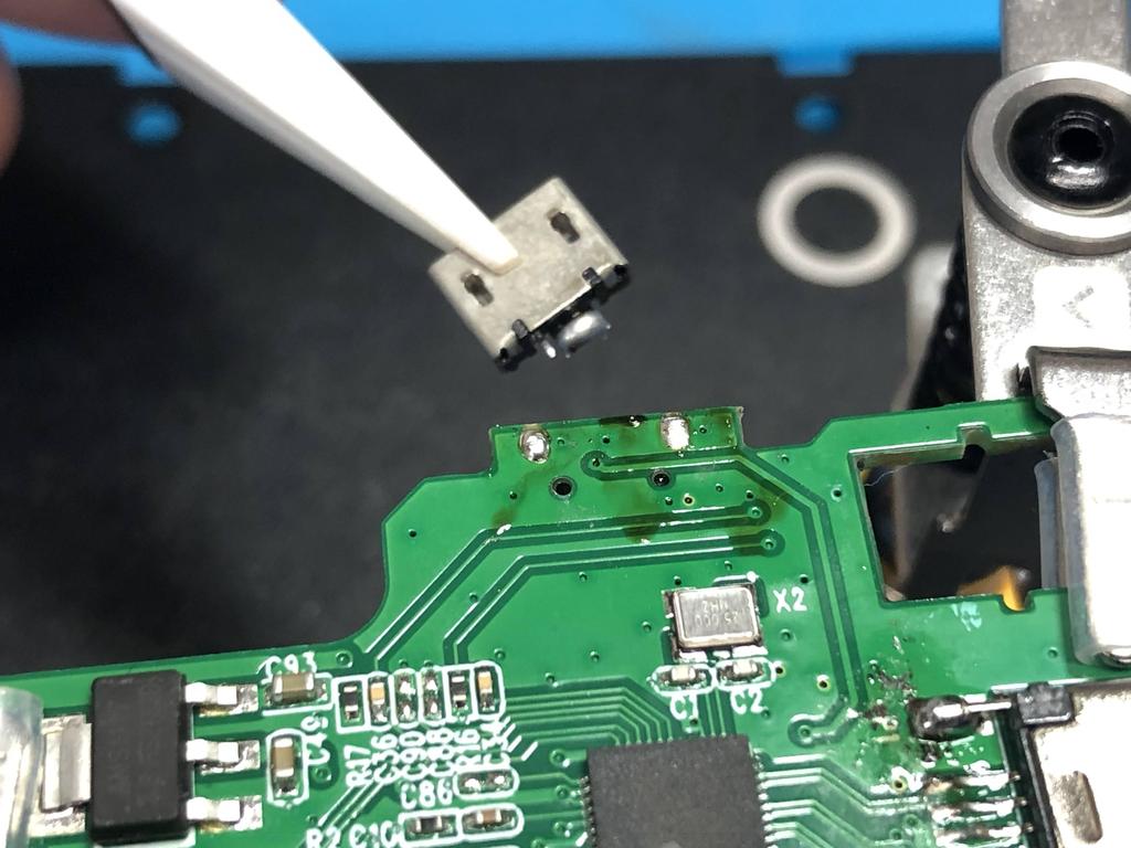
As well as the micro-usb power connector:
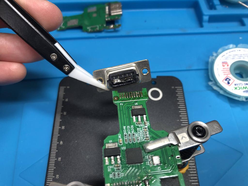
And finally, the VGA input connector:
With all that done, it was time to solder the adapter to the gbs board. Using ribbon cable, I soldered the R, G, and B pads, as well as ground:
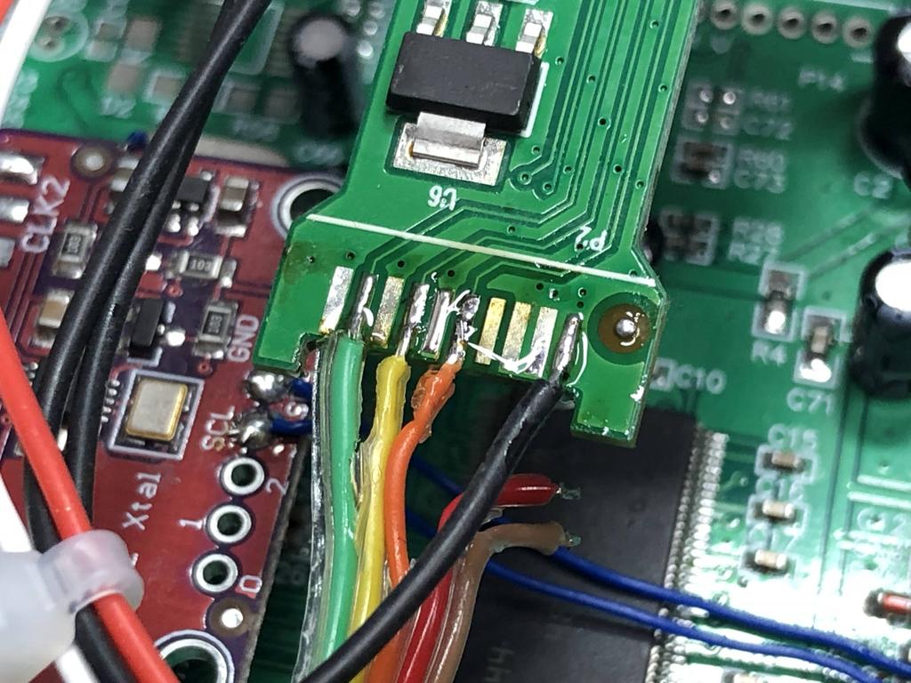
And on the other side, the H-sync and V-sync pads:
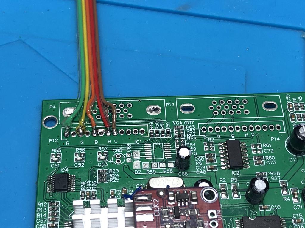
The other end of the ribbon cable was soldered to the pins that sat behind the VGA output connector I removed:
Note that ground wire isn’t connected above. You’ll see it connected in later pics.
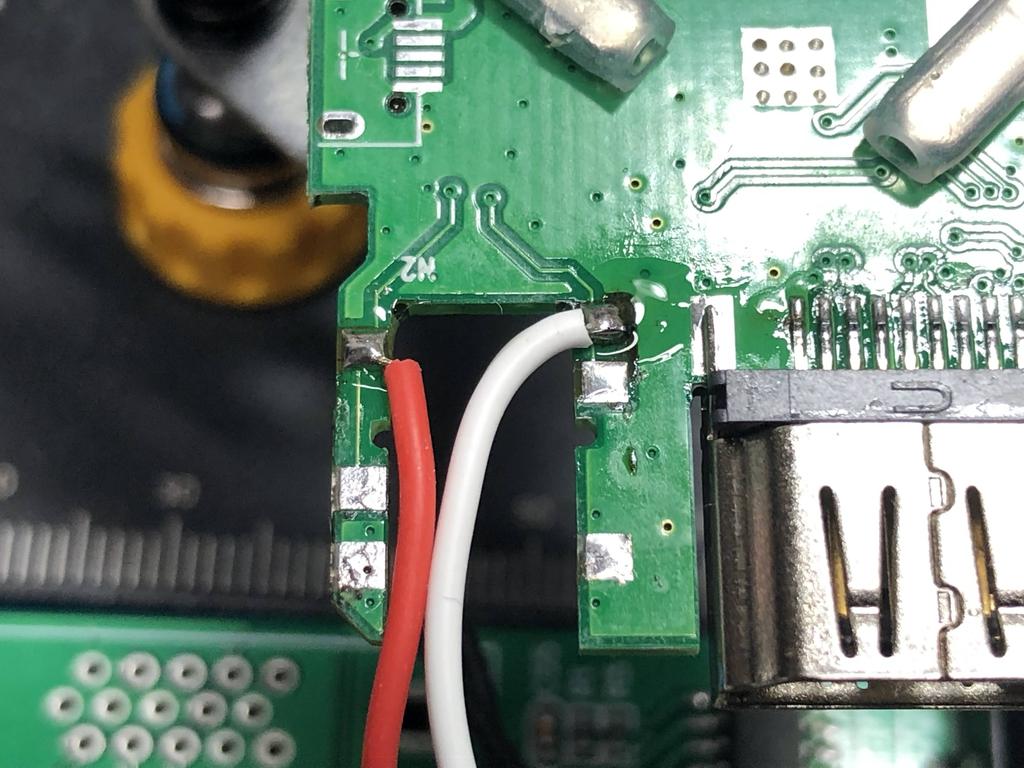
I soldered a red and white wire - for right and left audio, respectively - to the adapter where the audio input jack used to be:
On the other end, I soldered two ground wires for the audio signals:
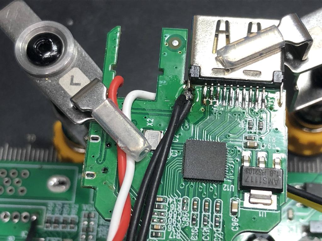
You’ll see these four wires getting hooked up to the RCA input jacks at the front of the case later below.
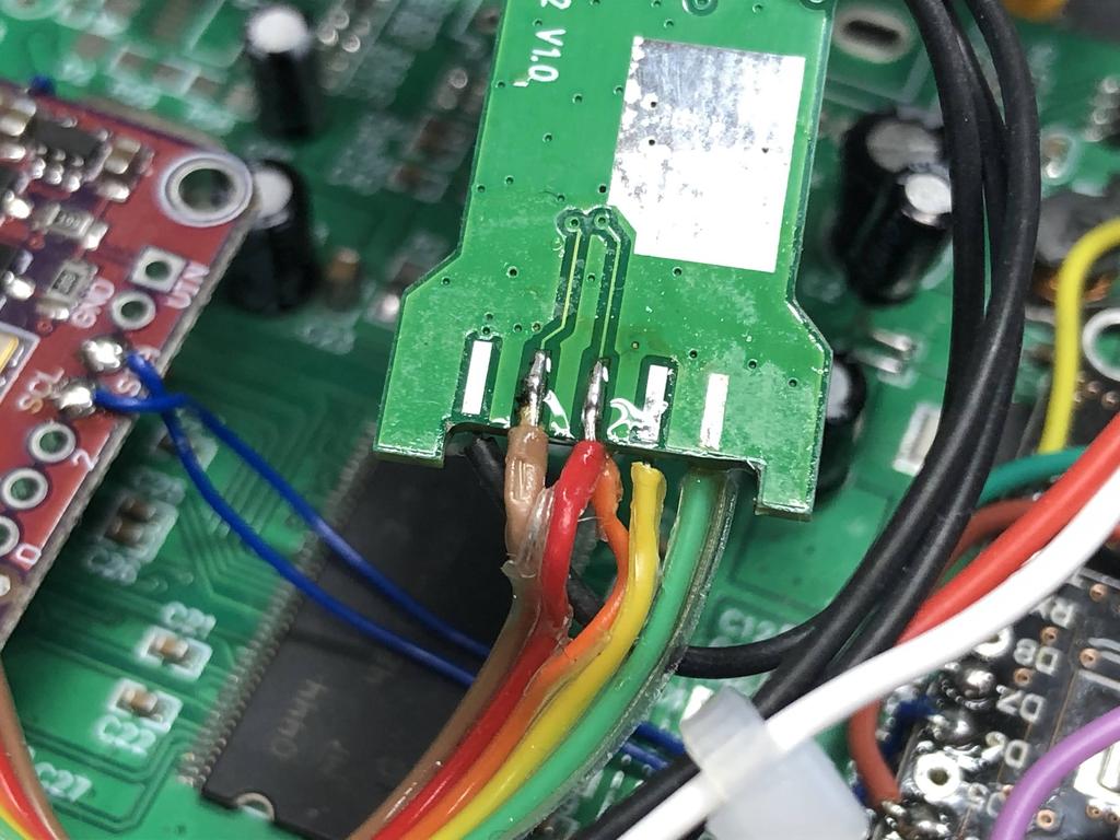
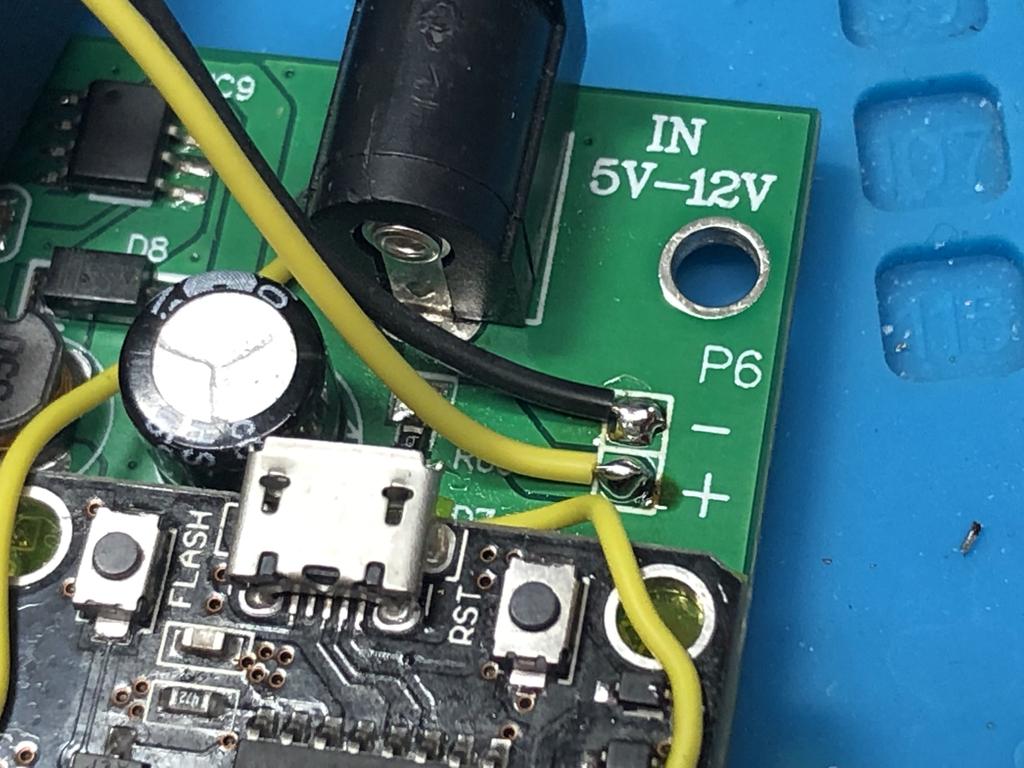
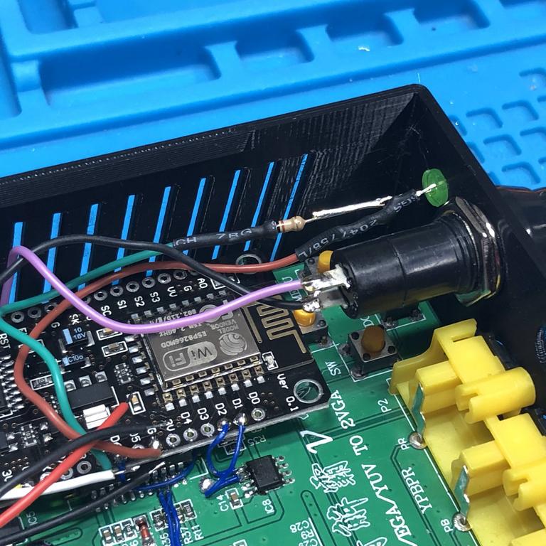
To power the adapter, I soldered a yellow wire for 5V and black for ground to this component:
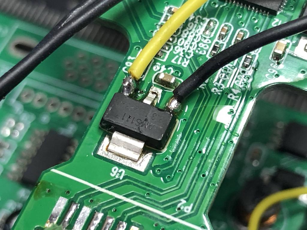
Then soldered the other ends to the gbs board:
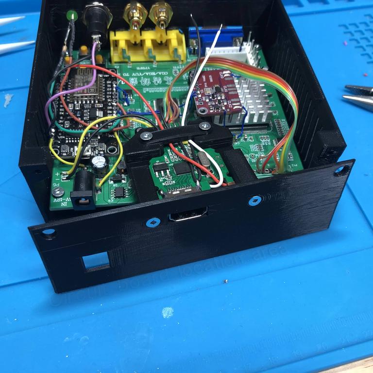
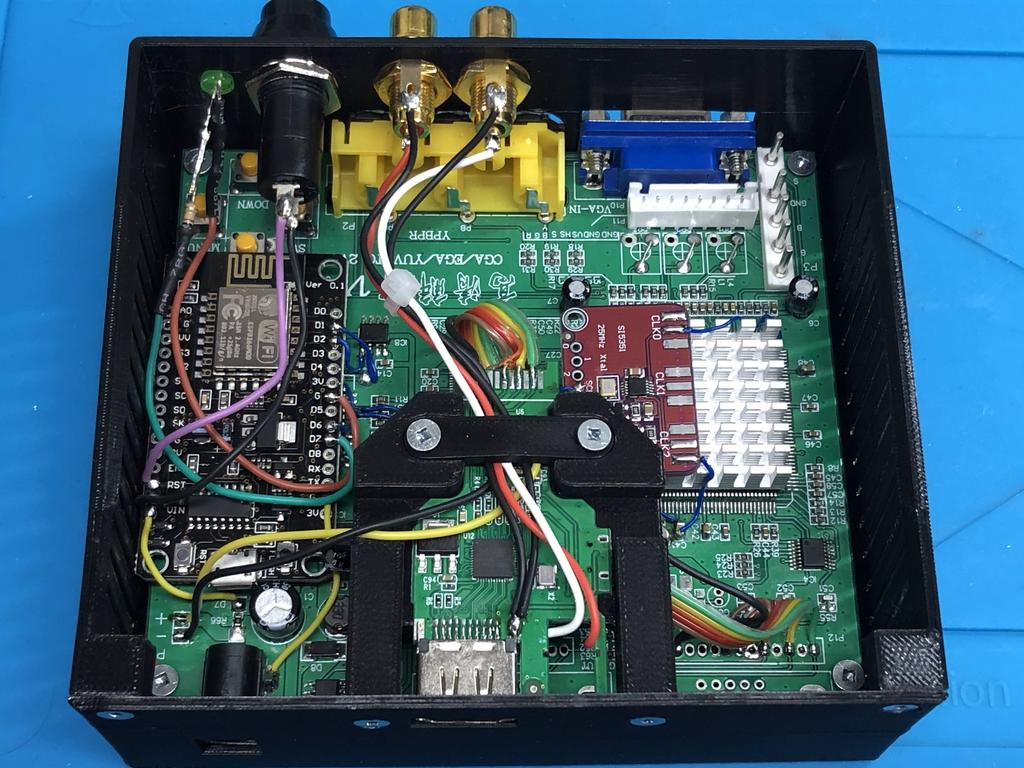
I placed the gbs board into the case, and screwed in the four corners:
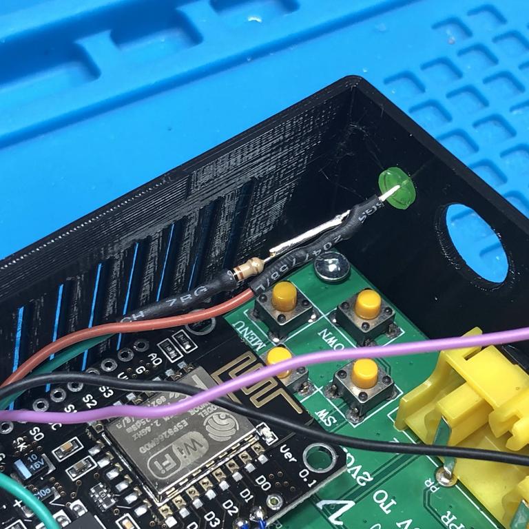
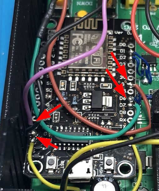
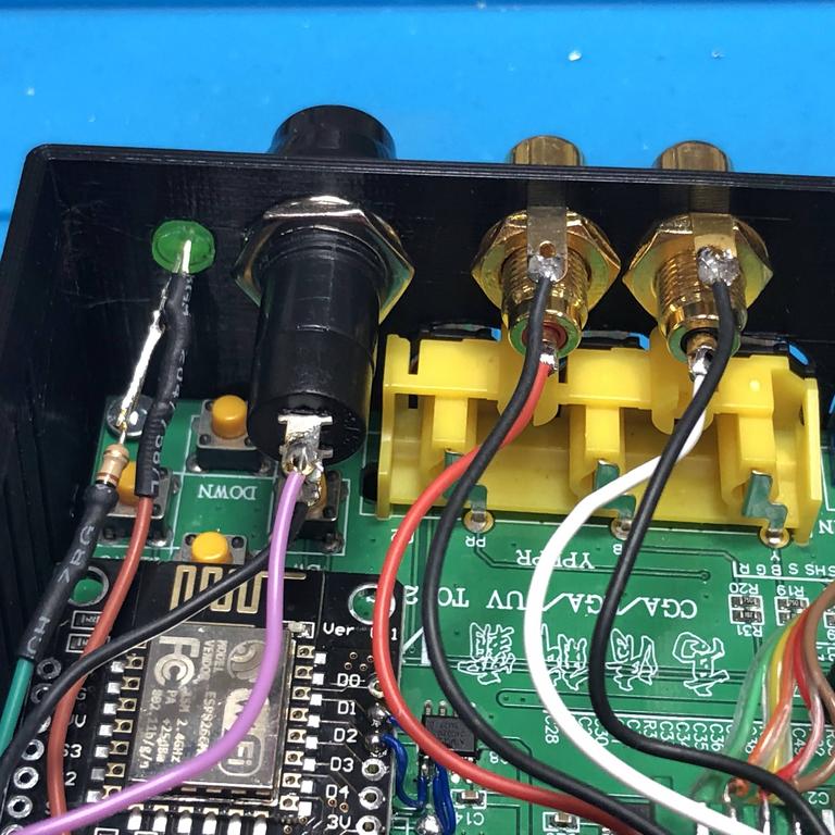
Next up were the status LED and reset button:
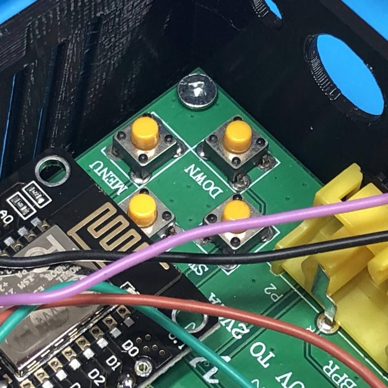
The other ends are connected to the NodeMCU board as shown below. The purple reset wire is tied to the RST pin (obscured in the pic), with the black ground wire next to it. For the LED, the green wire is tied to pin D7, and the brown to ground:
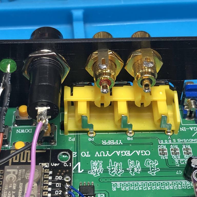
With the LED and reset buttons done, I screwed in the RCA audio input jacks:
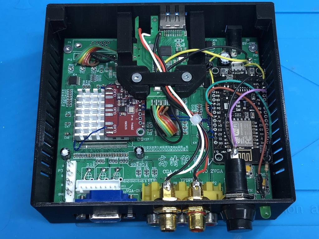
Next, I placed the HDMI adapter into its cradle, and screwed it to the back panel:
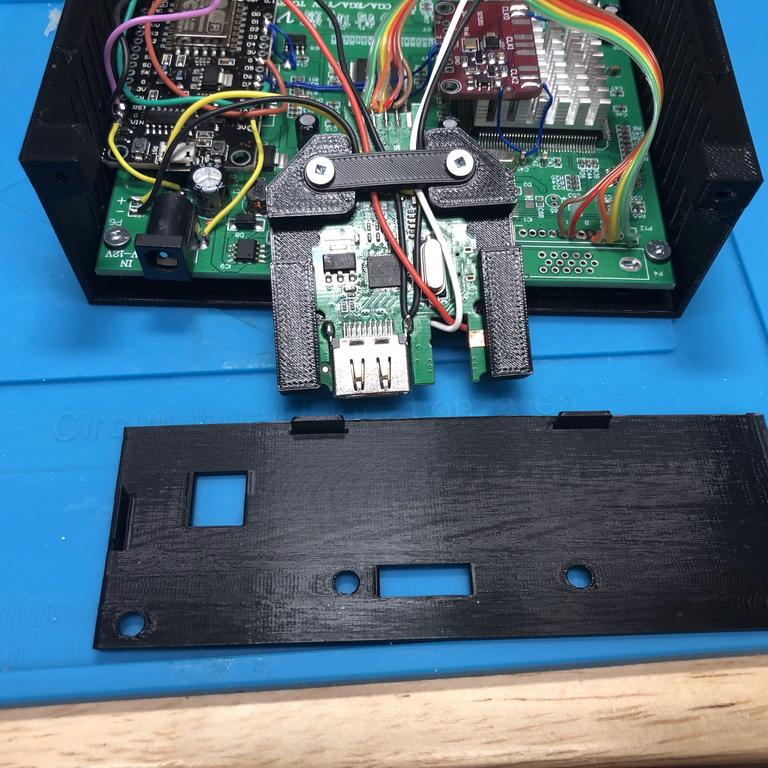
I then screwed the back panel to the case:

Finally, I soldered the audio wires coming from the HDMI adapter to the RCA jacks:
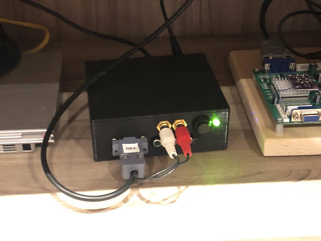
And with that, I was done!
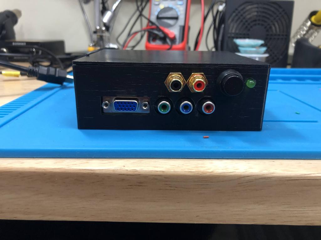
Here it is, with my N64 hooked up to it:
Thoughts #
I have to say that I’m really happy with the way this case turned out! This was practically my first time designing something more complicated for 3D printing, and although it took quite some time, I learned a great deal and had fun doing it.
The case isn’t perfect. For instance, the walls are a bit thin at 2mm, and I can feel them bending a little when I push in cables into it, especially on the back. I’d definitely try making it a little thicker. But apart from minor things like that, overall, I’m quite happy with the result.
In the next post, I’ll go over how I made a similar case for my second gbs-control that I use for down-scaling/transcoding.