gbs-control Case for YPbPr Out
In my last post, I went over how I designed and built a case for my gbs-control used for up-scaling with HDMI output. This post will be about my second case, designed for the gbs-control I use for down-scaling/transcoding with RGB/YPbPr out.
Design #
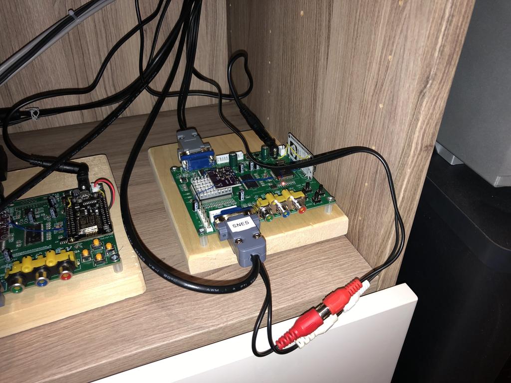
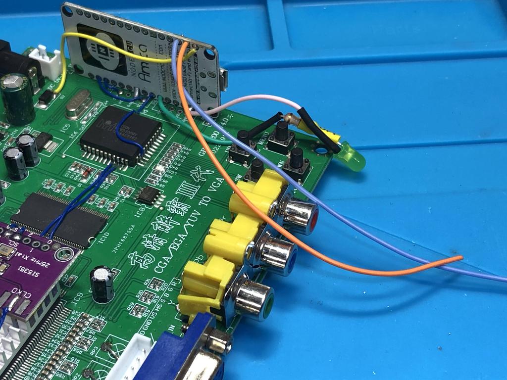
My second gbs-control is used for transcoding and down-scaling input signals, usually from RGB to YPbPr, using a custom DB-15 to RCA cable to feed the YPbPr signal to my CRT, along with a stereo RCA extension for audio:
Here were my design goals for this second case:
-
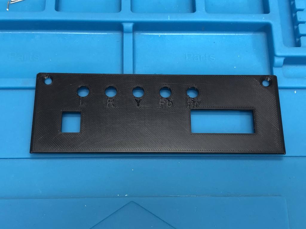
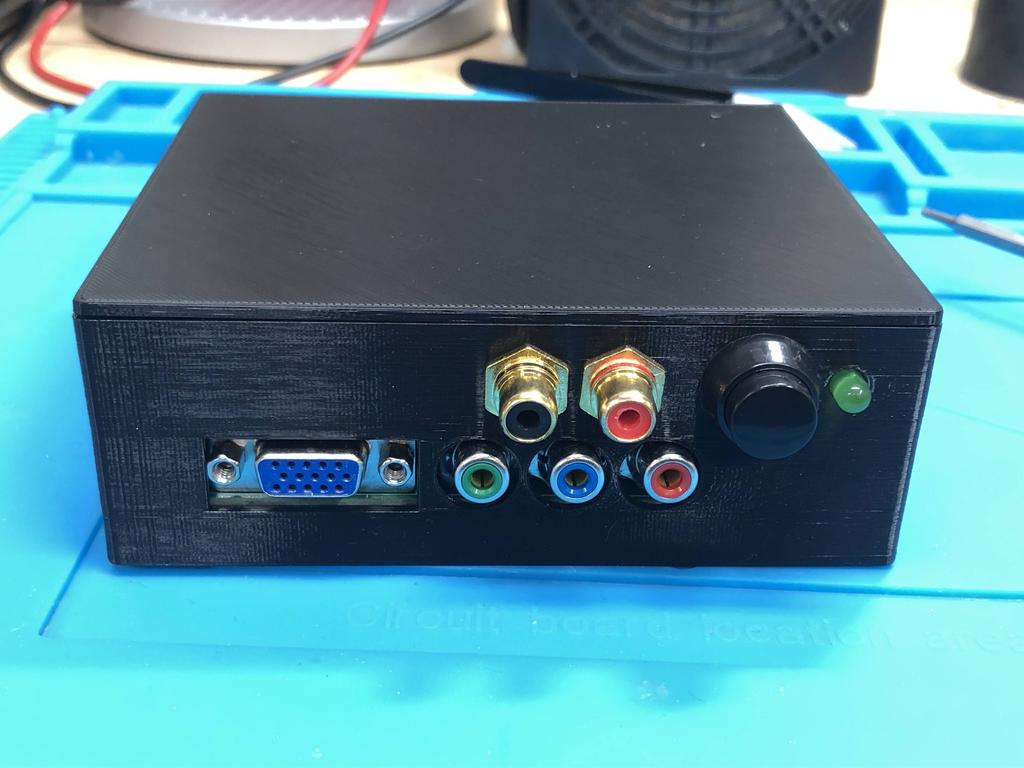
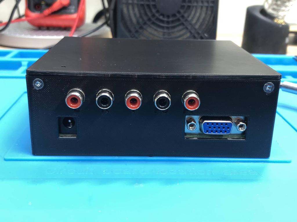
Keep the VGA out connector, but also add 5 RCA output jacks to the back panel to carry YPbPr (or RGB) along with left/right audio. This would allow me to hook up this gbs-control directly to my CRT using regular RCA cables, rather than my custom one.
-
As with the HDMI case, I wanted the same reset button and status LED on the front panel.
Having made the back panel a separate piece in my original design, all I had to do was design a new one:
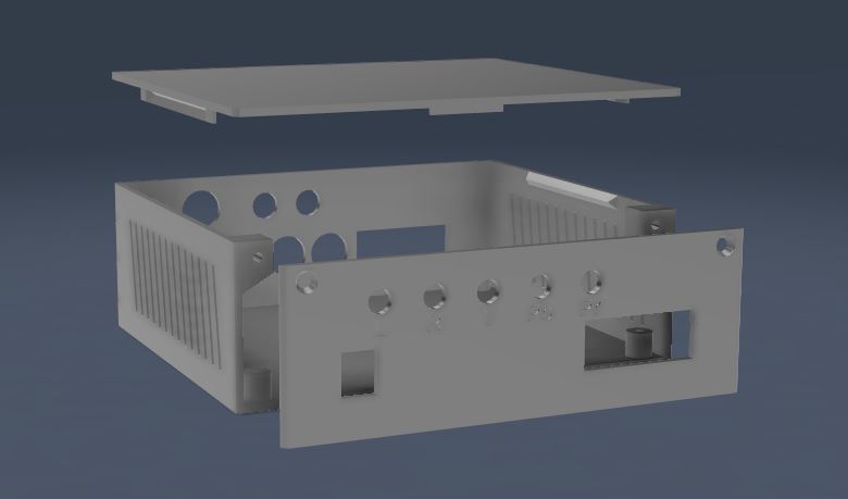
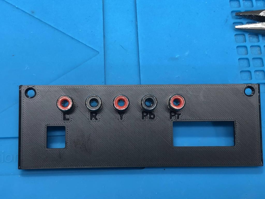
I decided to label each of the RCA output holes because finding RCA jacks of the right color isn’t easy.
Parts #
Here are all the parts I needed to build this:
- A fully assembled gbs-control with the Node MCU positioned along the edge - see my post here.
- A green LED
- 100 ohm throughole resistor for the LED
- #4 x 3/8” wood screws (846-020) - 6x total: 4 to attach the GBS to the case, and 2 to attach the back plate to the case.
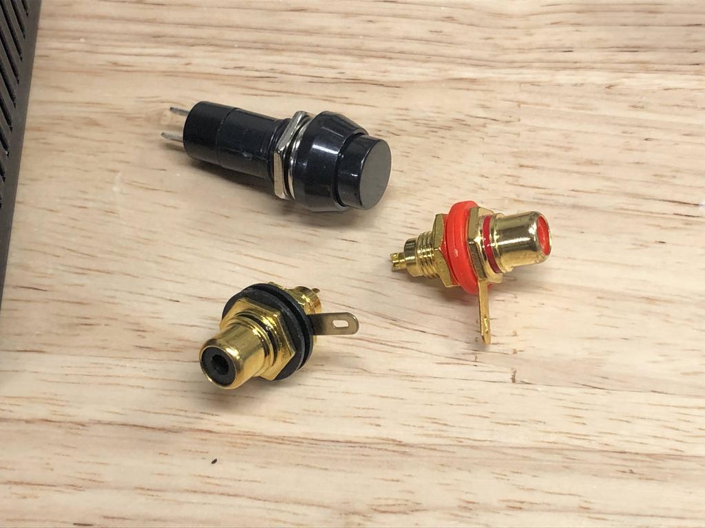
- Momentary button - the “hole diameter” must be 10mm. The ones I bought were from a local store, but I’ve linked one on AliExpress that I think should work.
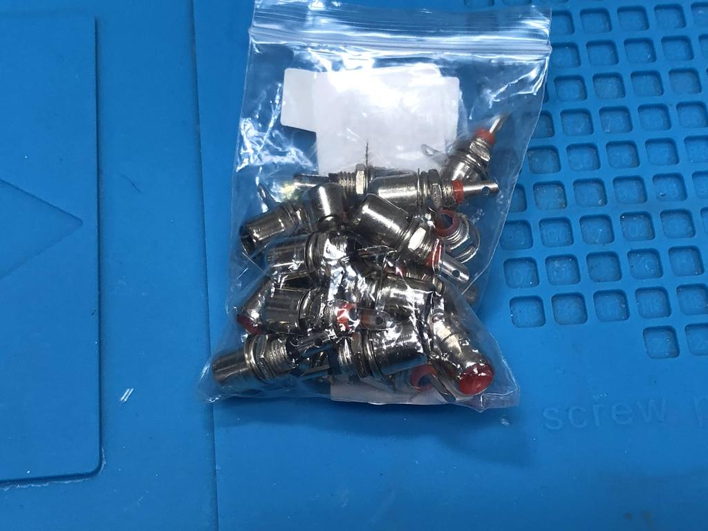
- 7x RCA female socket connectors - the “hole diameter” should be 5.6mm. In this post, I used 2 larger ones for the front, but I’ve since updated my design so that the 2 in the front panel, and the 5 in the back panel, are all the same size.
- 4x rubber feet to stick underneath the case
- 3D printed case
The Build #
This process went smoother than the for the HDMI case. The one hitch was that I had two versions of the gbs board, a V4 and a V5, and I didn’t realize that they weren’t exactly the same size. I had to make the case a little smaller for the V4 used in this build. But apart from that, it was pretty smooth sailing.
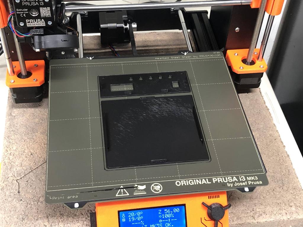
I printed all the parts again:
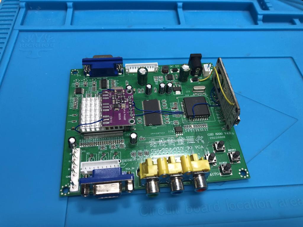
This is the V4 board destined for this case:
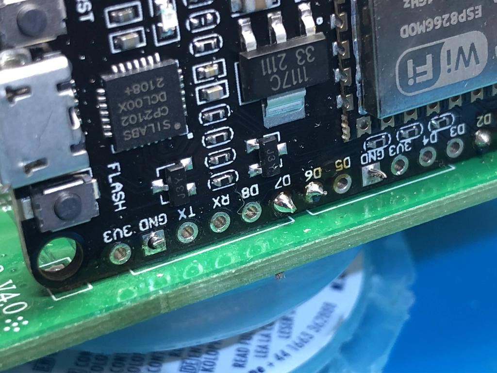
I desoldered this header that shares the connections from the VGA output connector next to it:
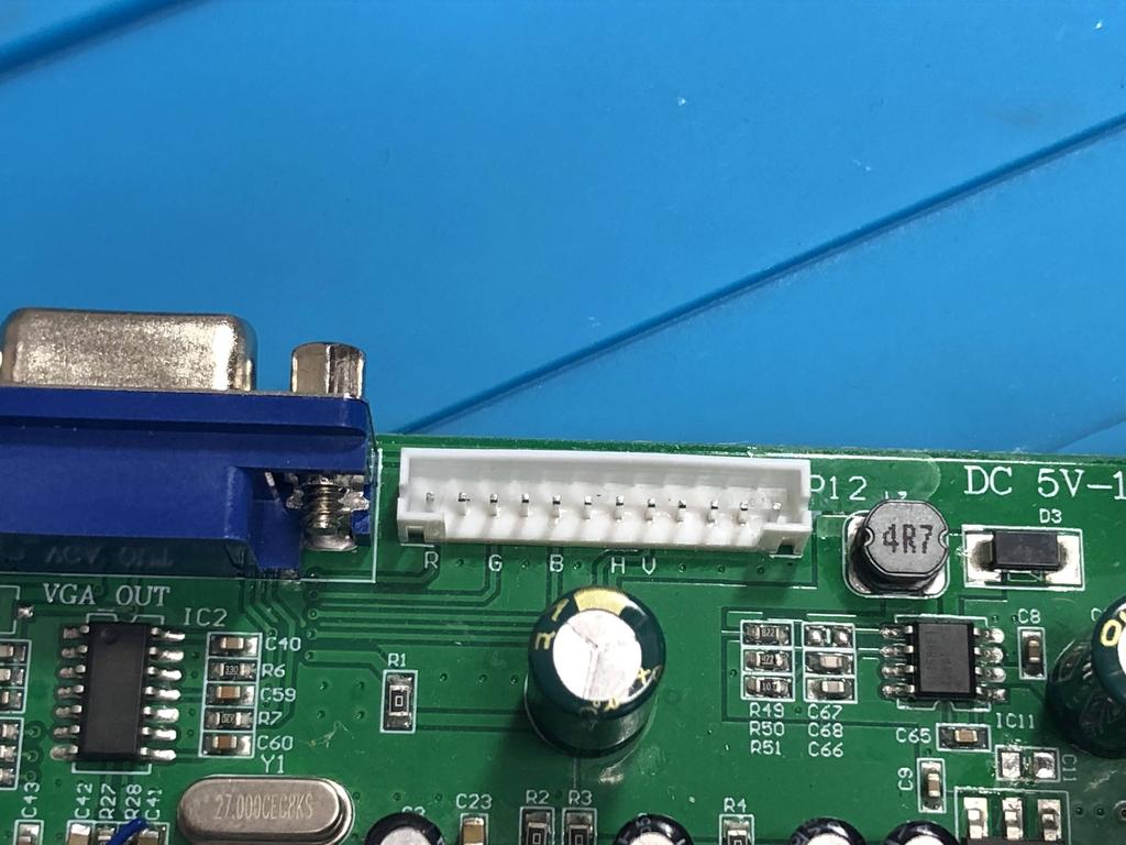
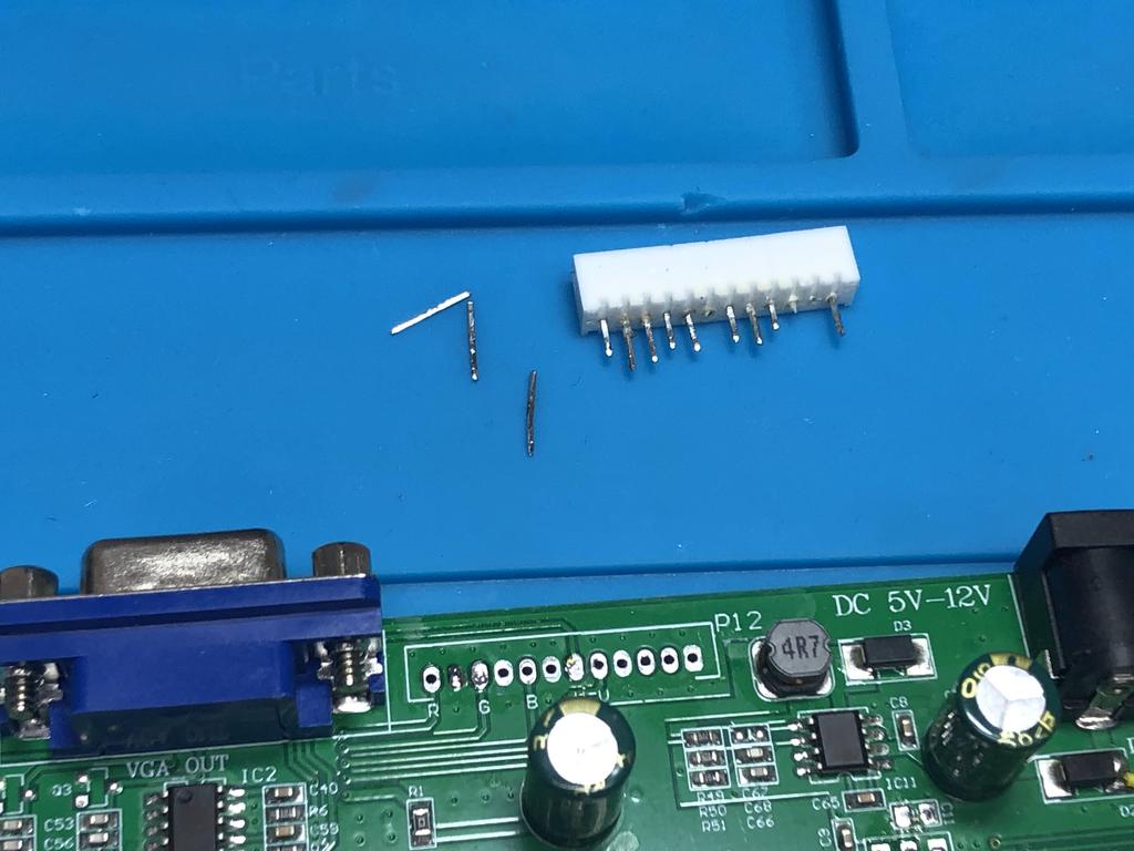
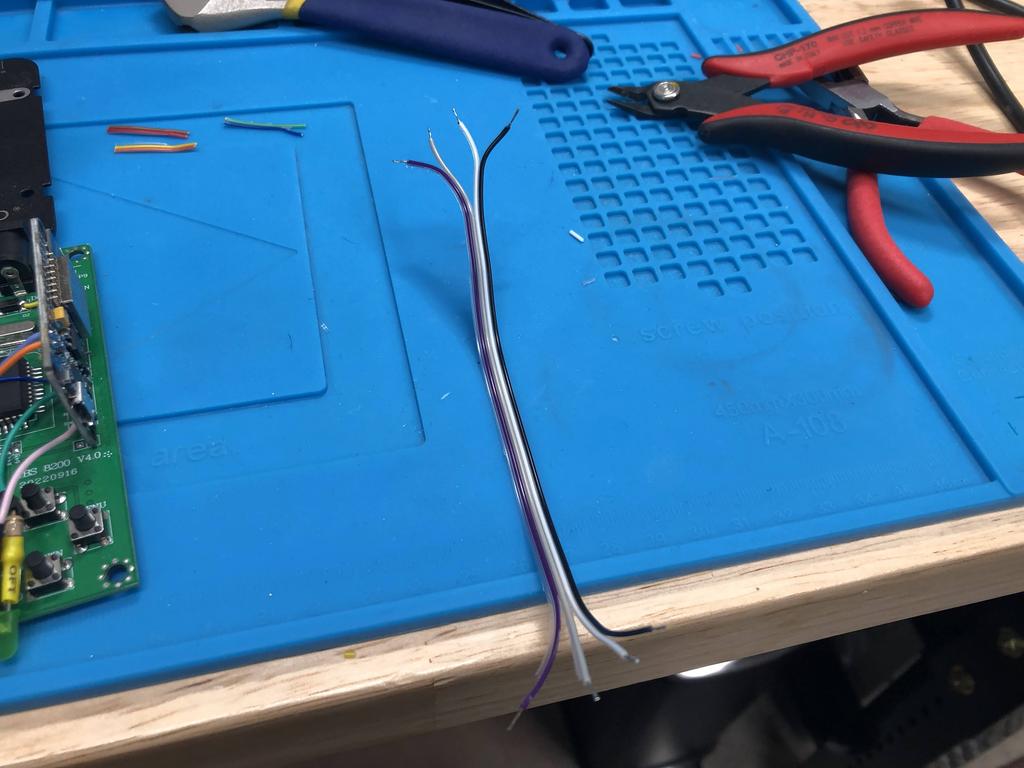
I soldered a ribbon cable to the exposed pads. This time, I only needed the red, green, blue, along with three ground connections:
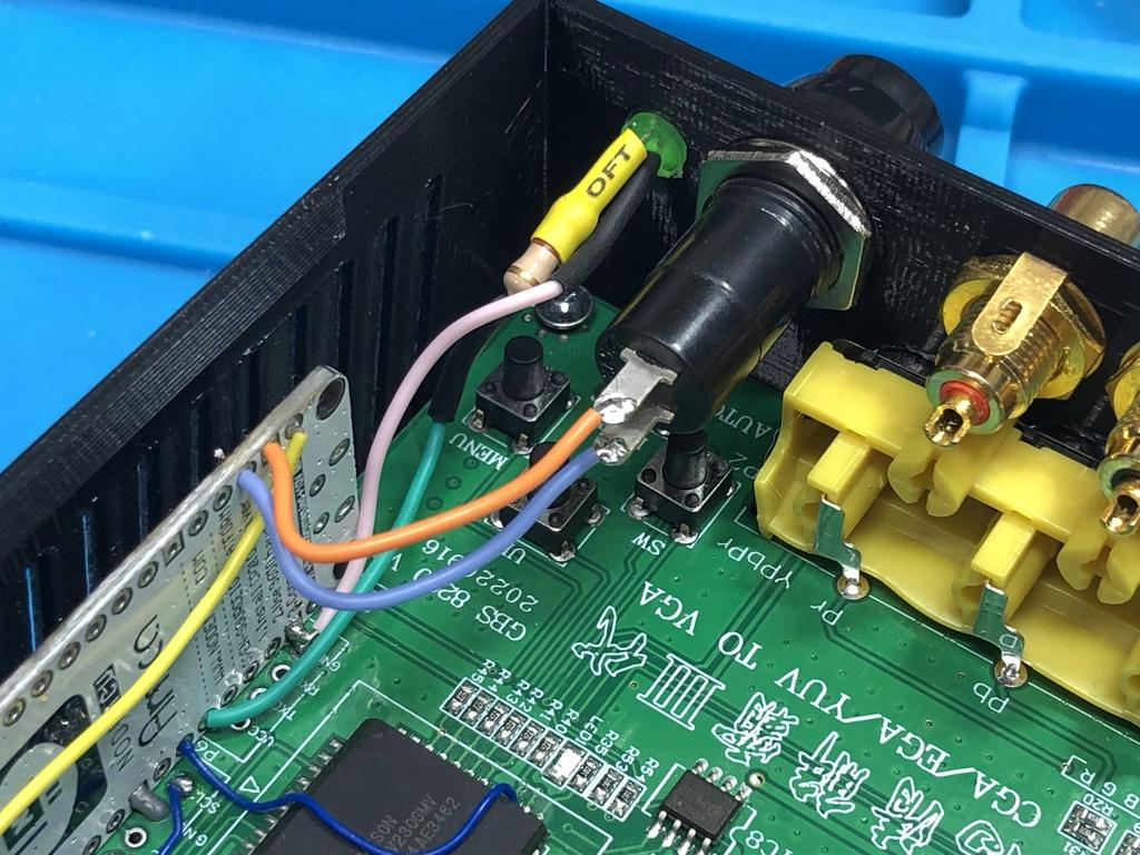
As before, I soldered a resistor to one of the legs of a LED:
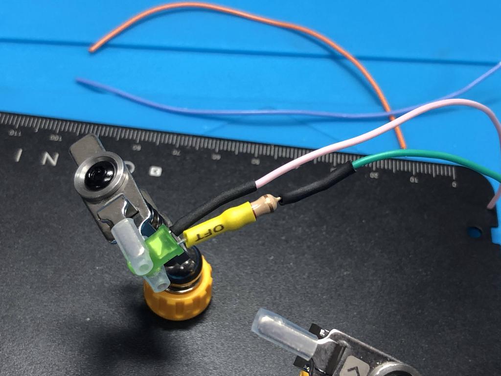
One leg (green wire) is connected to D7, and the other (pink) is connected to ground:
For the reset button, I soldered two wires to the RST and ground pins:
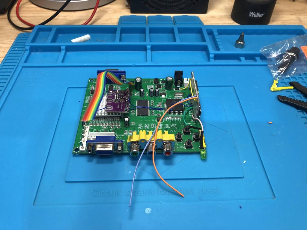
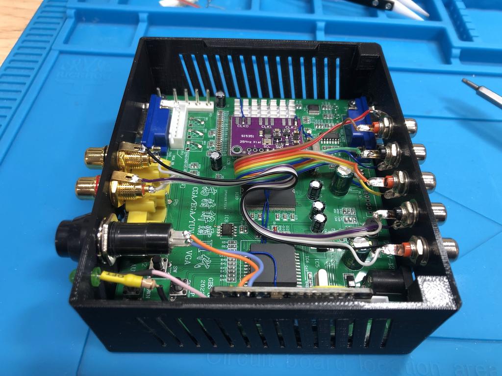
The board was now ready to be put into the case:
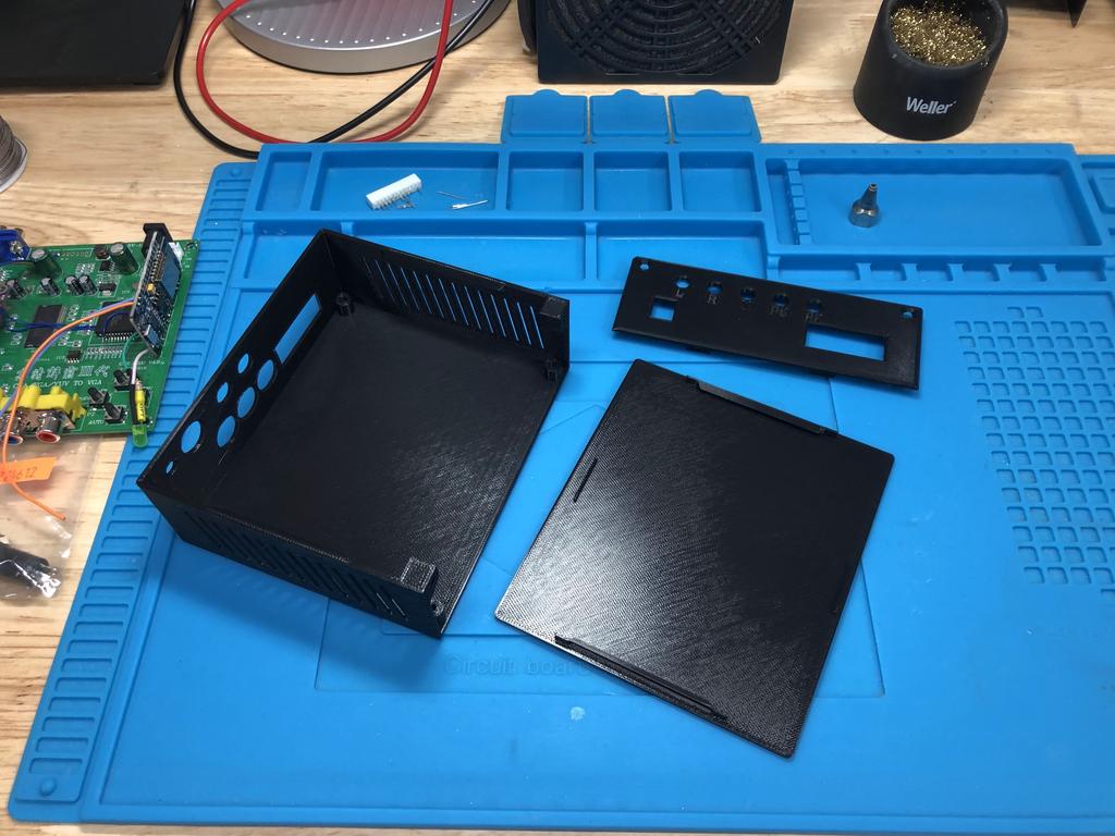
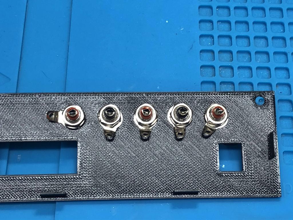
Here’s the new back panel:
I bought a set of 20 RCA connectors off Amazon for the back panel for $14 ($0.70 each), which was a lot cheaper than the ones I had bought for the front ($2 each):
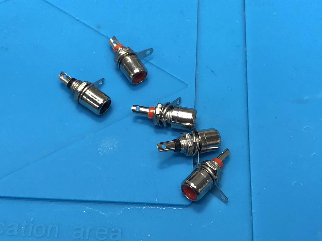
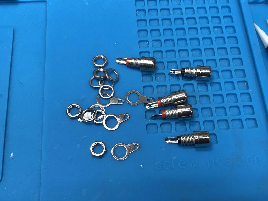
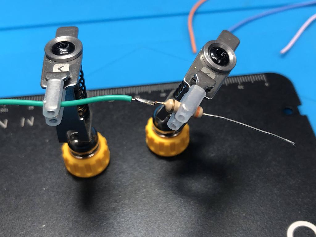
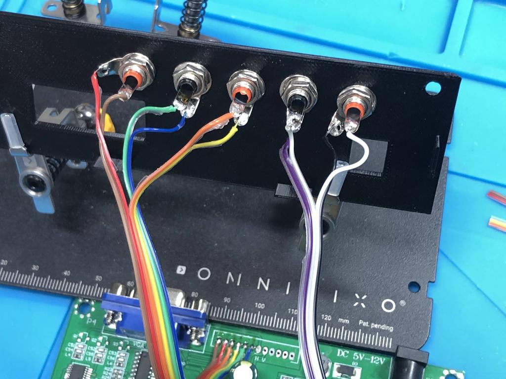
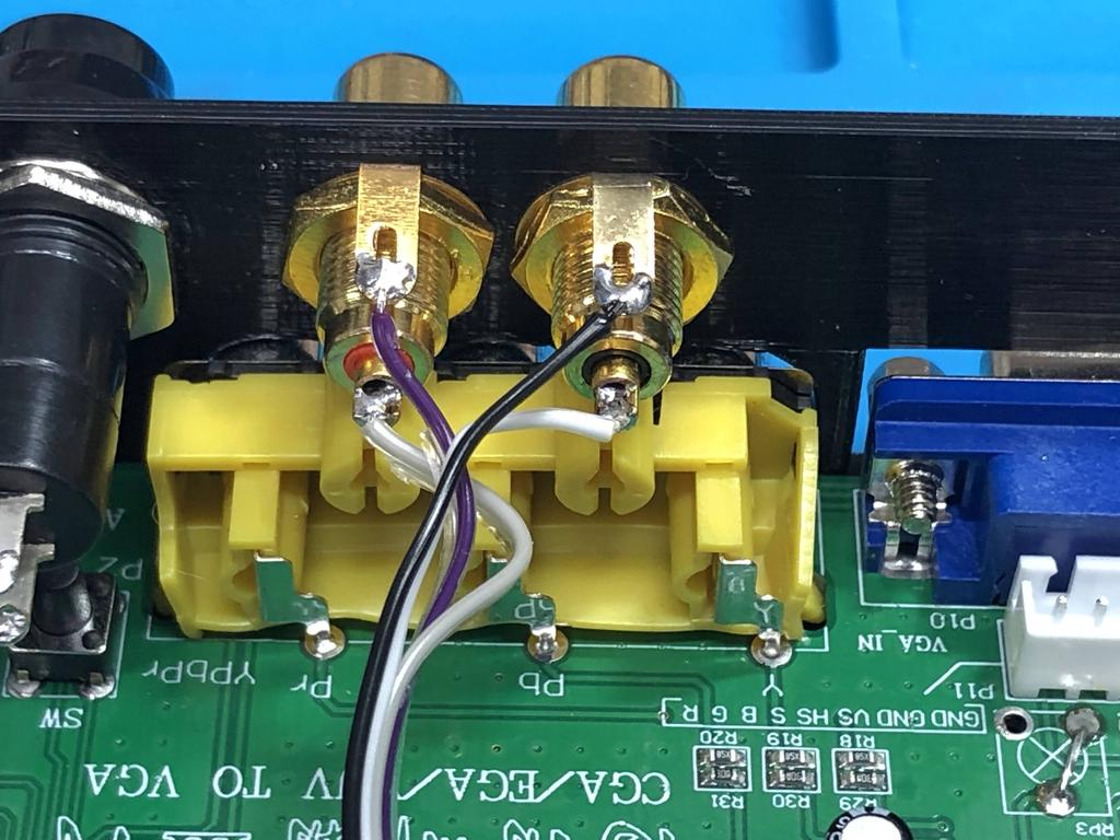
I screwed them into the back panel:
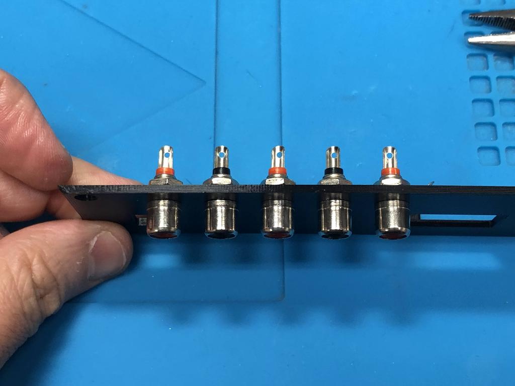
I oriented the ground tabs away from the power and VGA output connectors:
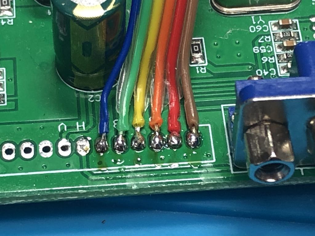
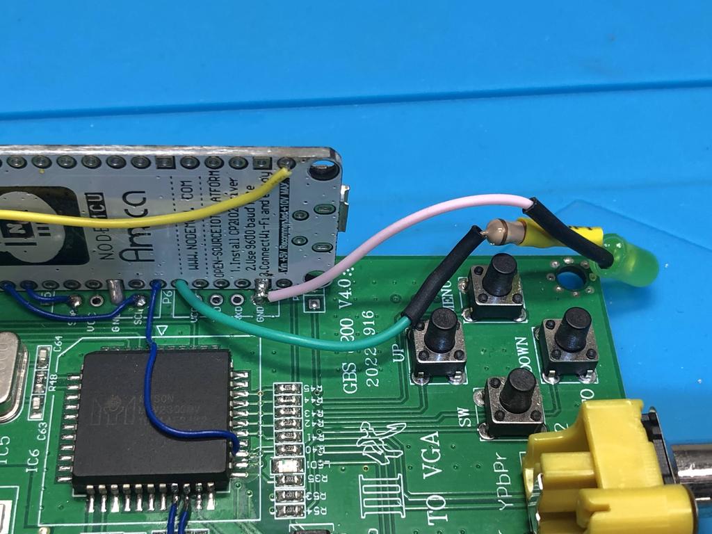
I soldered up the red, green, and blue connections. For the gbs-control, when YPbPr mode is enabled, red maps to Pr, green to Y, and blue to Pb:
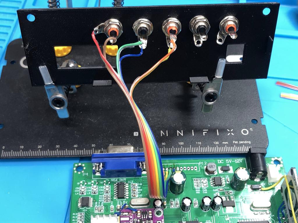
For audio, I used another ribbon cable:
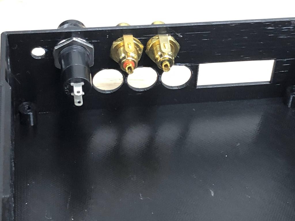
Next I installed the reset button and audio input jacks:
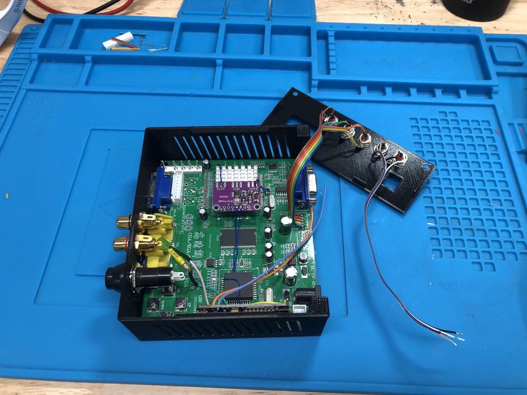
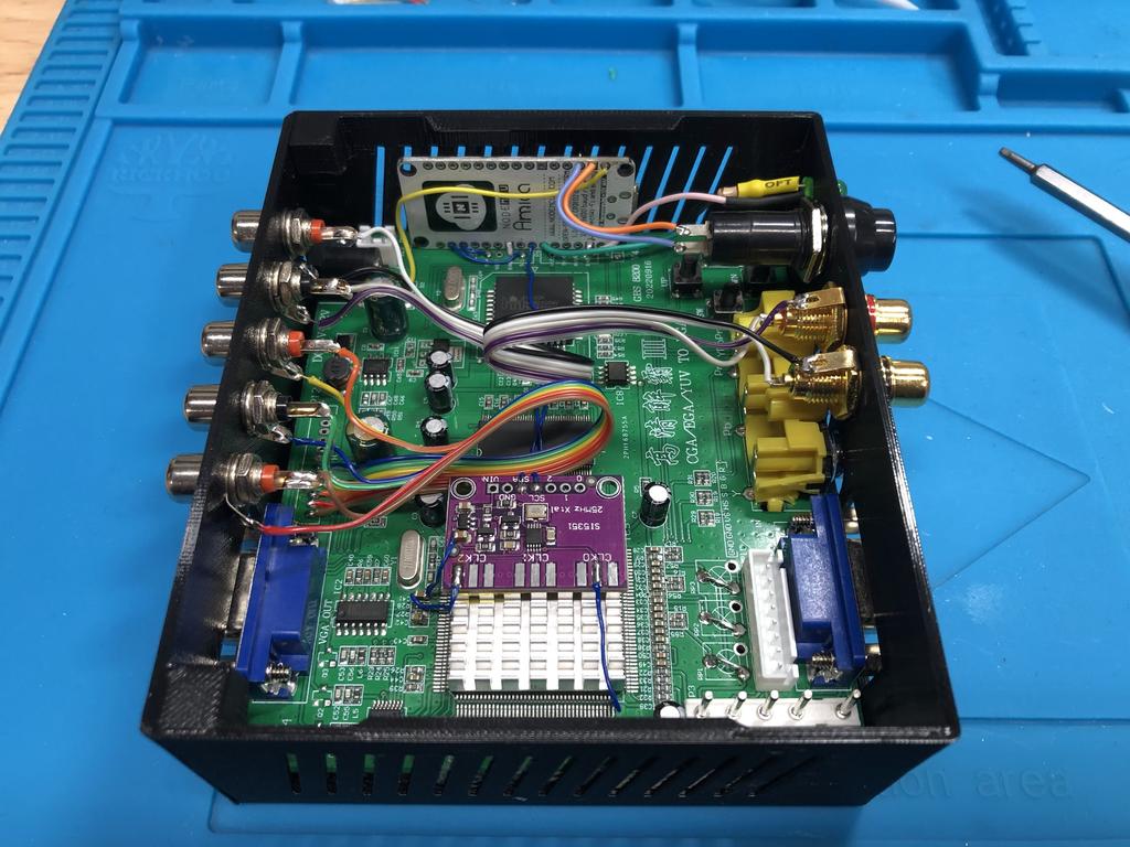
I slid the board into the case and screwed it into place in the four corners:
I soldered up the reset button:
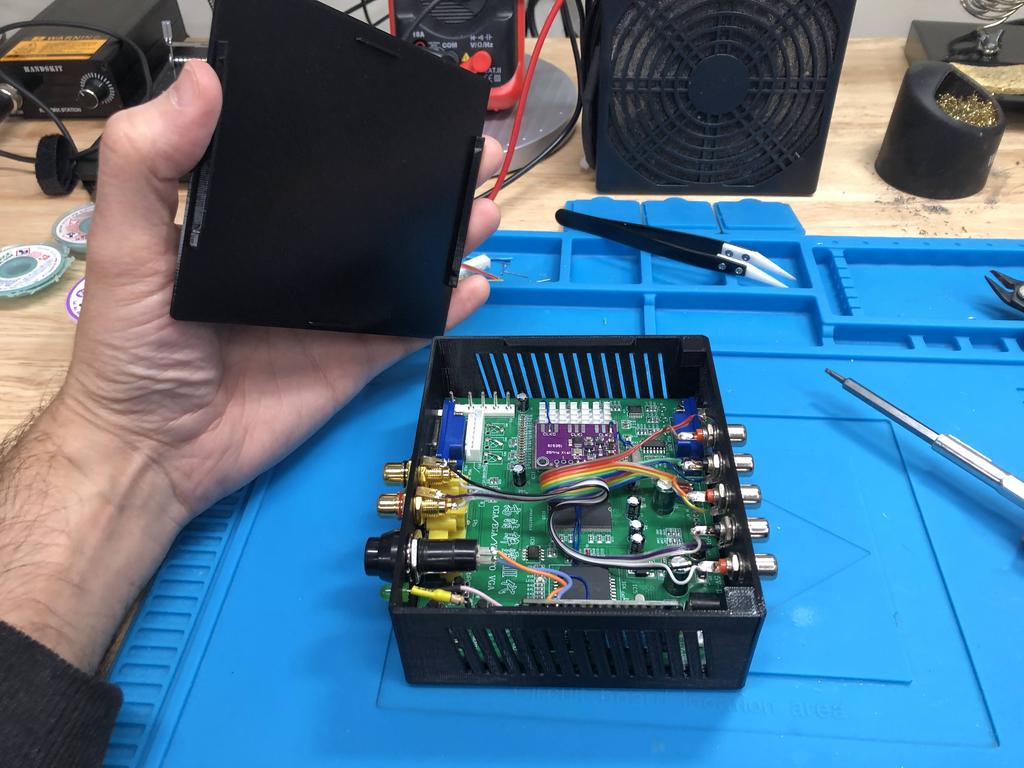
Then screwed in the back panel:
And finally soldered the other end of the audio ribbon cable to the RCA input jacks, being careful to swap the ends so that left and right are correctly oriented:
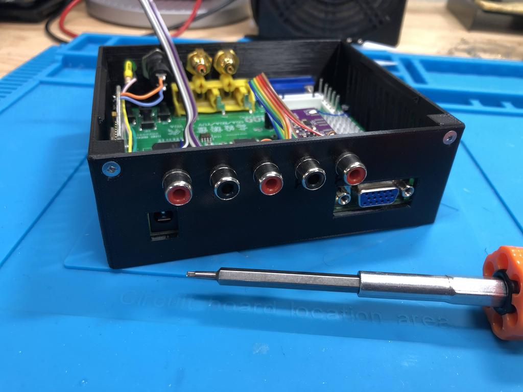
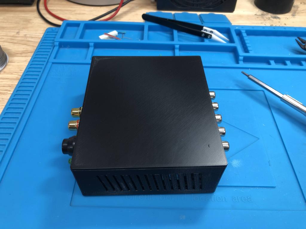
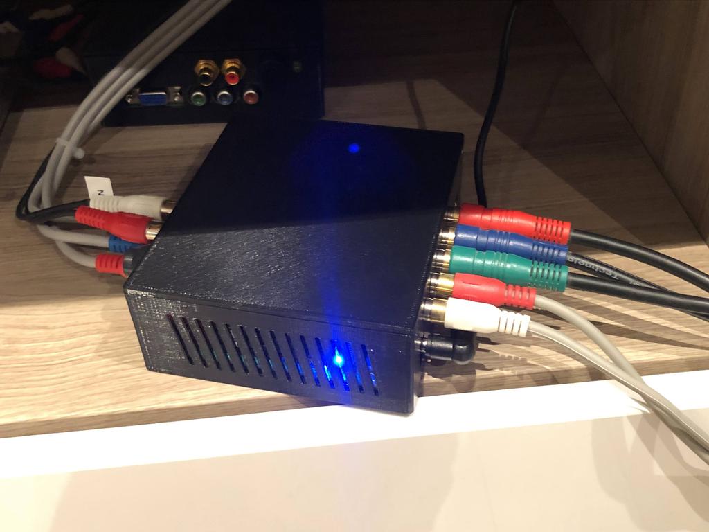
All done, and looking mighty clean:
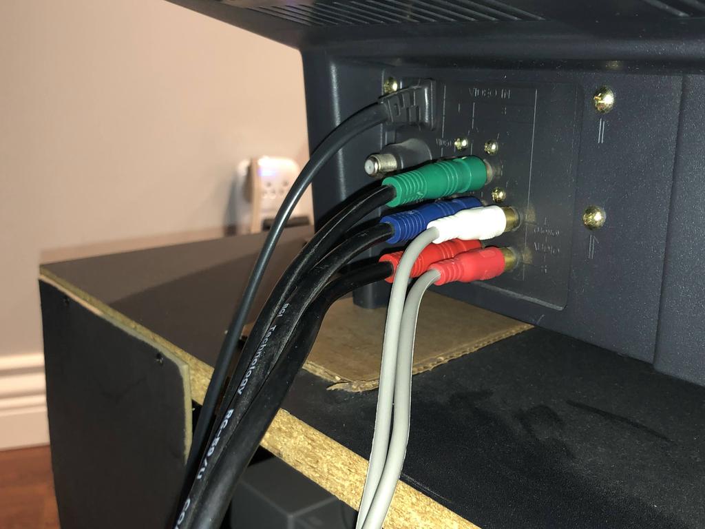
Here it is hooked up with regular RCA cables for YPbPr and audio going straight to my CRT:
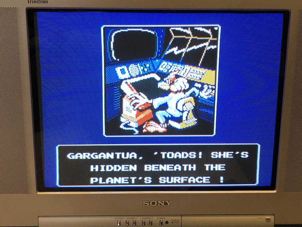
Success!
Thoughts #
Building this second case went a lot smoother than the first one, both because it was my second go-around, and also because I didn’t have to mess around with the VGA-to-HDMI adapter.
As with the first one, I would definitely make the case walls thicker so that they don’t bend when pushing in cables to connect them. Another thing I would consider doing is adding some artificial weight to the cases so that they don’t move around so easily.
Having said all that, I’m super happy with the final result for both cases. They look great in my setup – definitely a lot better than the exposed PCBs screwed into blocks of wood!