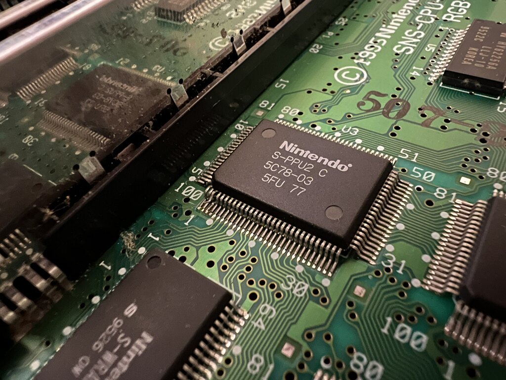
SNES 2-Chip RGB Filter Mod: SNS-CPU-RGB-02
A few months ago, I posted about how I modded my 2-chip SNES to improve the video output quality. The mod was based off of this post by Buttersoft, which is for the SHVC-CPU-01 revision of the SNES, and is exactly the model I have. In this post, I’m going to share how I helped someone get the same mod installed in their SNS-CPU-RGB-02 SNES.
After my initial post, someone by the name of axmccx reached out, wanting to perform the same mod. After sending him the pre-soldered mod board, we discovered that his SNES revision was a SNS-CPU-RGB-02. I wasn’t sure if this mod would work on this revision; but once again, unmaker from the ConsoleMods Discord came to the rescue, and pointed us as this shmups post by davidmorom who did exactly that.
With axmccx’s permission, I’m going to share his pics of how to install this mod board on a SNS-CPU-RGB-02.

Parts #
The list of parts is pretty much the same as for the SHVC-CPU-01, with these differences:
-
For this revision, you must leave the three transistors on the main board, so you need to buy three extra transistors to install on the PCB itself.
-
axmccx didn’t end up installing the 8x 10uf X7R 0805 ceramic caps on the main board, mostly because we couldn’t figure out where to stack them! In any case, the final picture quality was amazing, so they may not be necessary for this revision.
The Build #
Follow the steps in my original post to populate the PCB with all the components, except that instead of transferring the three transistors at Q3, Q5, and Q7 from the main board to the PCB, solder three new ones onto the PCB.
On the SNS-CPU-RGB-02, the three equivalent transistors are located at Q1, Q2, and Q3 on the main board. We first need to lift the base leg of each, and put a little Kapton tape underneath the legs to make sure they don’t short:

Next, we need to wire up the PCB in between the transistors legs we just lifted, and the pad they were connected to (actually, we connect to vias conveniently located next to the pads). I put together this image as a guide for axmccx:
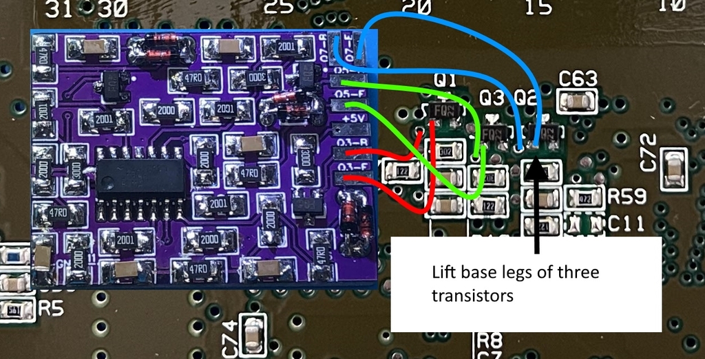
Basically, we connect six wires for red, green, and blue by hooking up the base (“B”) pads on the PCB to the base vias, and the emitter pads (“E”) to the lifted transistor legs. Also note that on the PCB, the “Q3” marking is now “Q1” on this board (red), Q5 is Q3 (green), and Q7 is Q2 (blue).
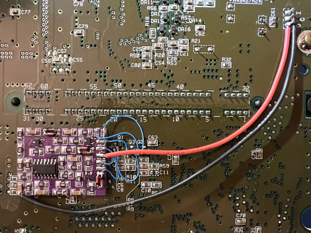
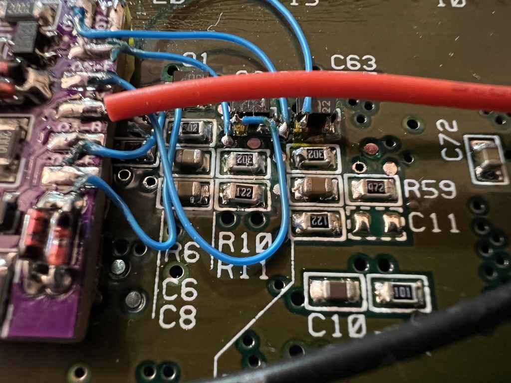
This is what it looks like wired up:

With all that hooked up, we now only need to hook up 5V and GND:
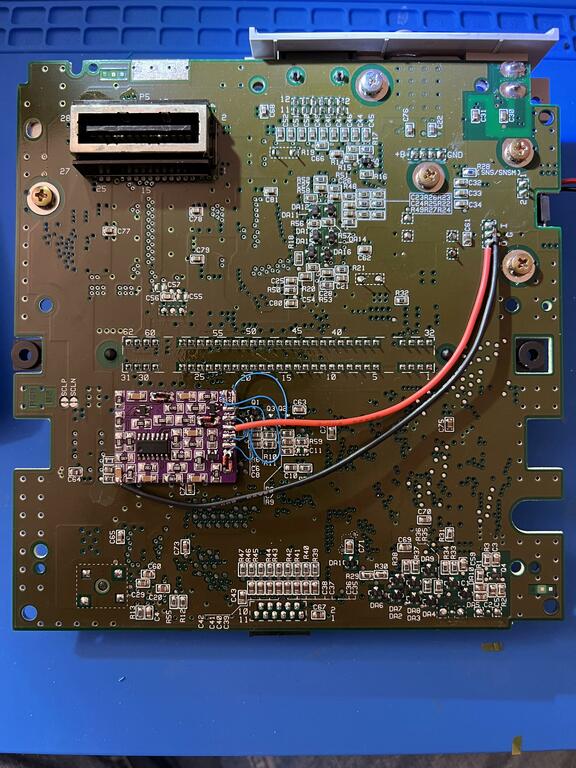
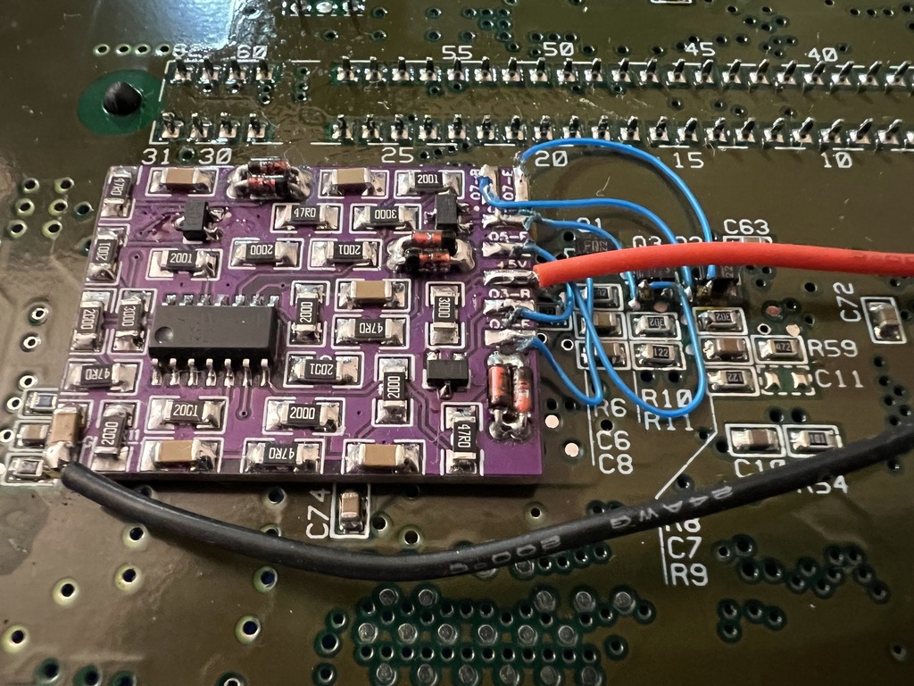
A few more pics from different angles:
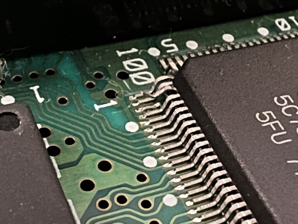
Finally, after some testing, although the ghosting effect was gone, there were still some diagonal patterns in the output. In the shmups post, davidmorom points out how he “lifted PPU2 pin 3, to remove the diagonal chroma sub-carrier interference (this is something almost mandatory in this board revision)”. axmccx did exactly that, and sure enough the diagonal patterns were gone! Here are pics of the pin lifted:
Results #
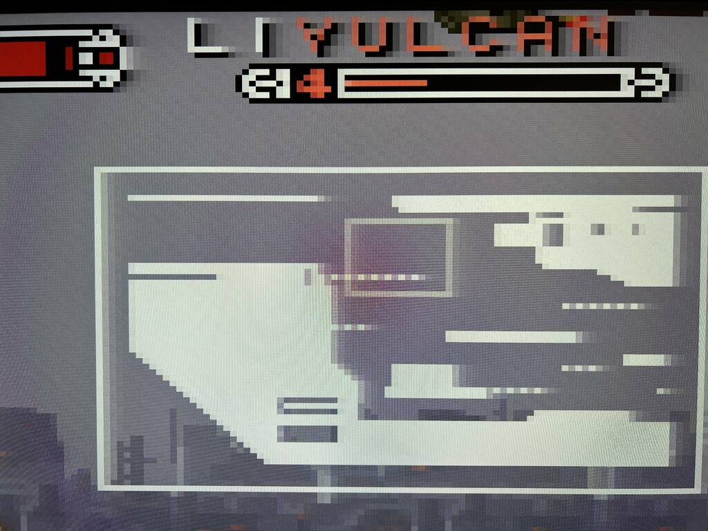
Here are some of axmccx’s comparison shots, taken of his TV with the SNES scaled via a RetroTink 5x Pro.
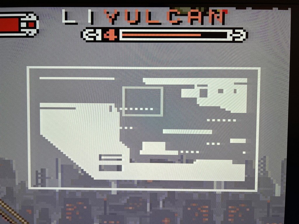
Un-modded (notice the ghosting):
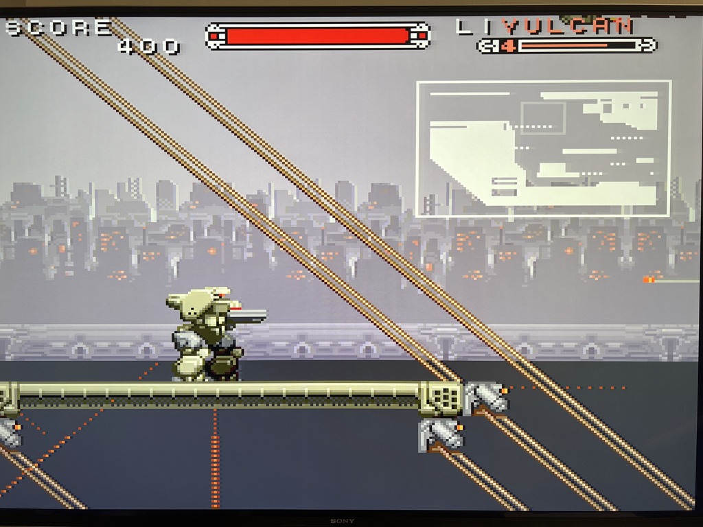
 With mod, but PPU2 pin 3 not lifted (notice the diagonal lines):
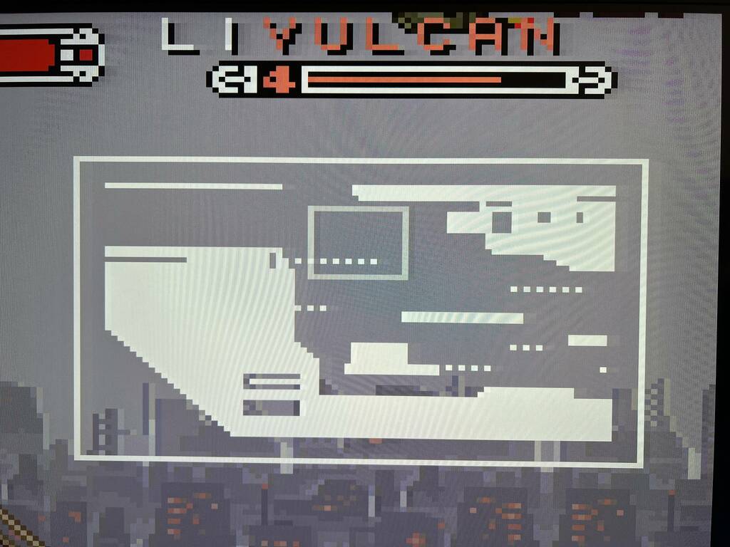
 With PPU2 pin 3 lifted (no more diagonals):
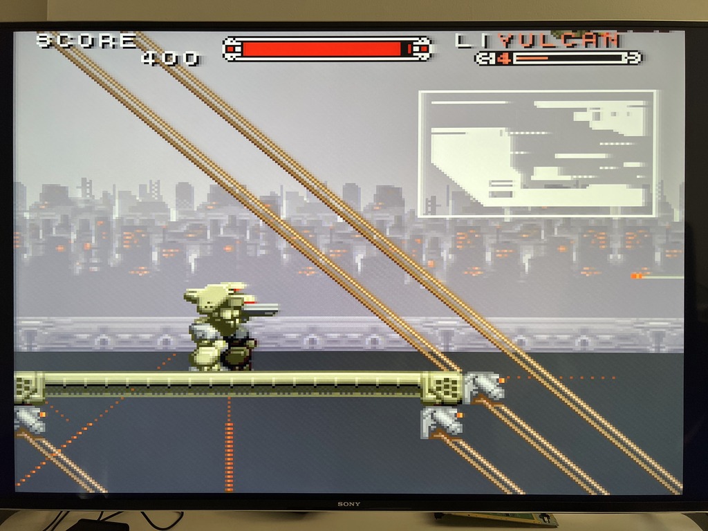
And another:
Un-modded:
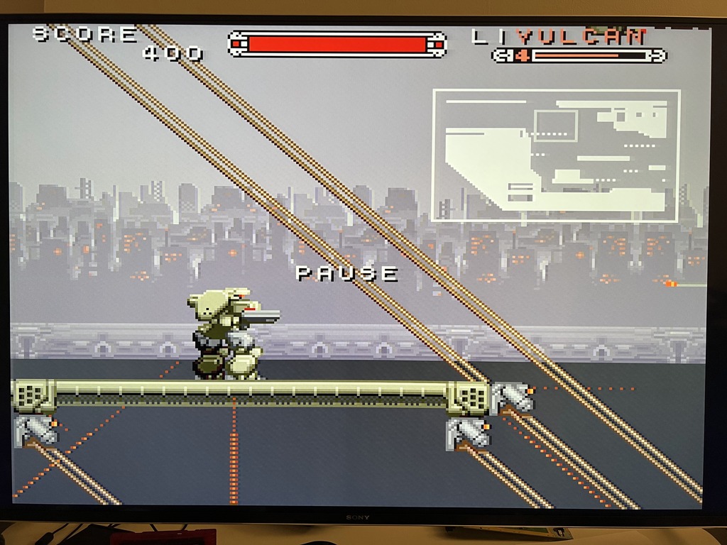
 With mod, but PPU2 pin 3 not lifted:
 With PPU2 pin 3 lifted:
Thoughts #
Once again, I think the results speak for themselves. This is a great mod for the 2-chip SNES, and hopefully this post will help those of you with an SNS-CPU-RGB-02 board to get this installed.
axmccx did an awesome job installing this mod. Thanks to him for sharing his pics, and a huge thanks to unmaker, as always, for being super helpful and awesome.