SNES2VGA
A while ago, I made a custom cable with a SNES/N64-style multiout connector on one end, and on the other end, a VGA connector to carry the video signal, along with two RCA connectors to carry the audio signal. I use this cable to connect my SNES or N64 to my gbs-control scaler, and although it mostly works, I’ve had a few connection issues recently. I eventually stumbled upon the SNES2VGA project by Jeff Chen, which is a much better solution, and in this post, I’ll go over how I built one.
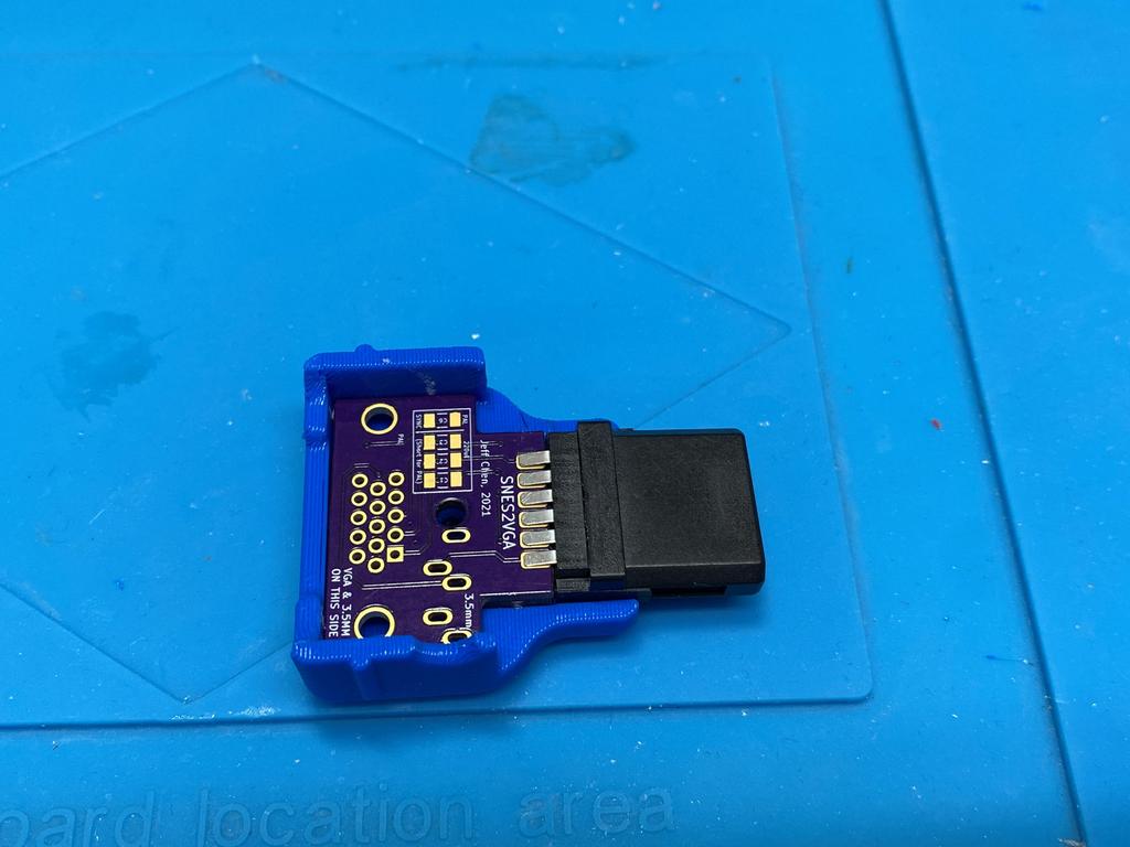
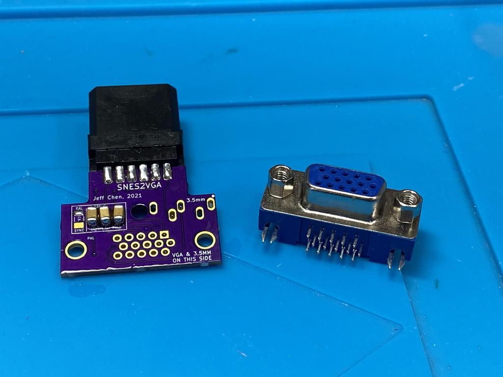
The SNES2VGA is a dongle that adapts the SNES/N64 multiout to a VGA-style female connector. This allows one to use a standard VGA cable to connect the console to the video input medium (e.g. scaler). The dongle also includes a female headphone jack so that a standard headphone wire can be used to connect the audio signal. Alternatively, the dongle also passes audio through two typically unused pins on the VGA connector, allowing only the VGA cable to be used alone if the receiving end can support it.
Parts #
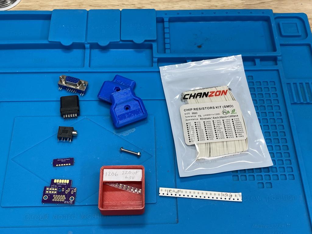
Here are the parts I used to make this dongle (prices converted to USD). (Check out the official BOM for links):
- 2 PCBs
- Main - 3x for $5.60 from OSHPark
- Sub - 3x for $1.10 from OSHPark
- Multiout plug - 2x for $6.70 from AliExpress
- Female VGA port - 10x for $3.84 from AliExpress
- Headphone jack - 5x for $2.43 from AliExpress
- 3D-printed shell: top and bottom - printed with my Prusa
- 1x M3x20mm screw and nut - $0.03 each from a 500 piece kit I bought from Amazon
- SMD components (common)
- 2x 0603 10uF 6.3V caps - $0.02 each from a kit from Ali Express
- SMD components for NTSC configuration + CSYNC
- 3x 1206 220uF 6.3V caps - $0.50 each from a kit from AliExpress
- 1x 0603 470 Ohm resistor - $0.003 each from a kit from AliExpress
For a single dongle, the total cost is about $8 each, not counting the 3D-printing cost.
Note that for the SMD components, what you need depends on whether you’re building for a NTSC or PAL system, as well as what type of sync signal you intend to use. Definitely check out the official BOM.
The Build #
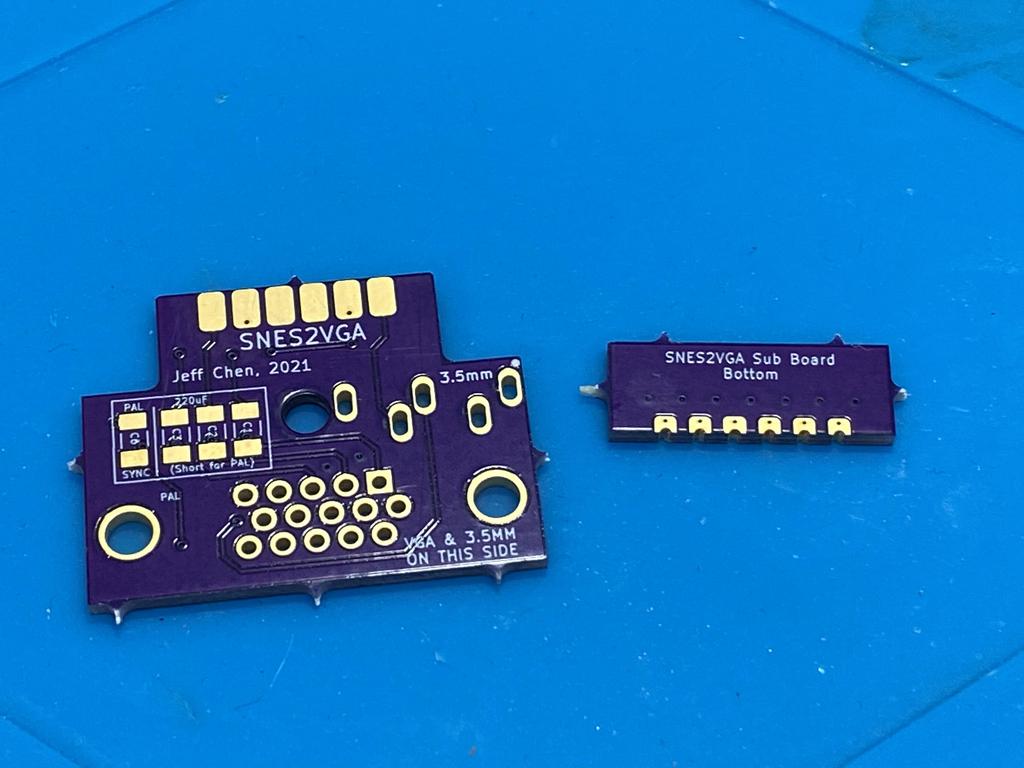
PCBs #
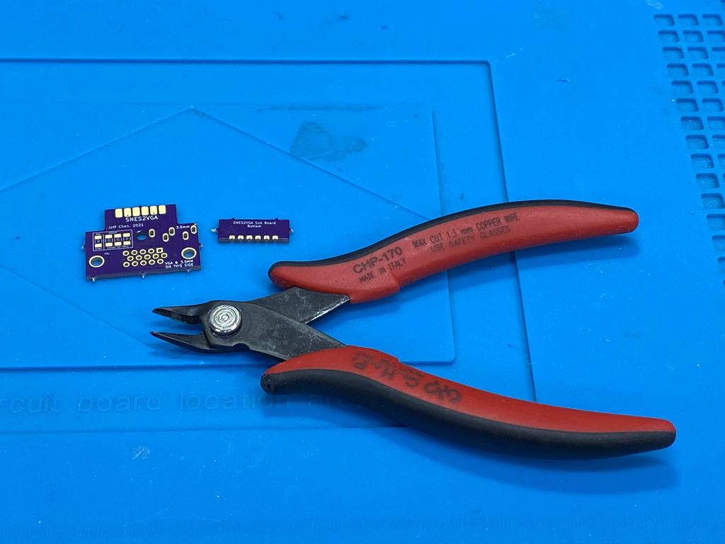
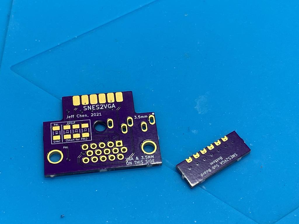
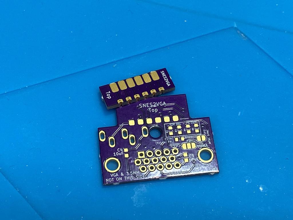
First, I used some flush cutters to cut the little spacers off the edges of the PCBs. This is important as the fit within the 3D-printed shell is very tight:
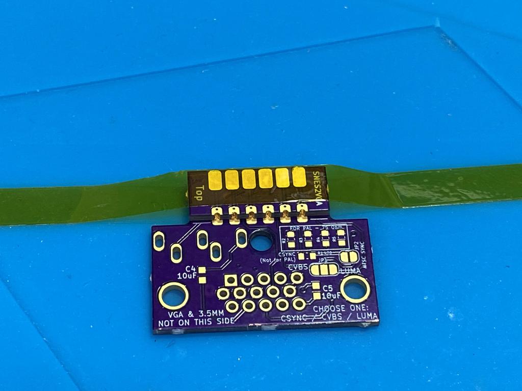
Next, I soldered the castellated edges of the sub PCB to the main one. I used some Kapton tape to help hold the sub PCB down:
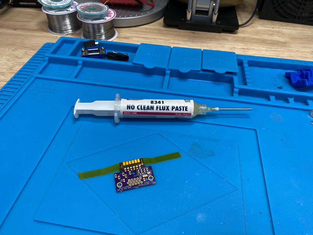
I added flux to help the solder flow:
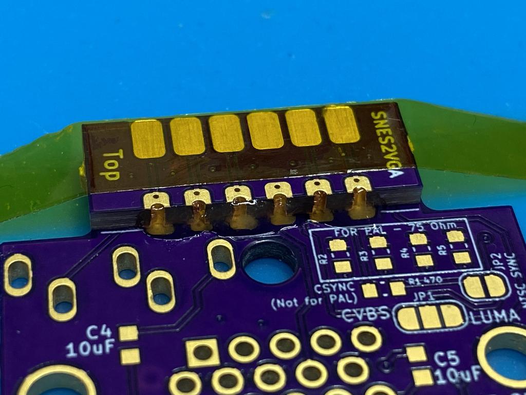
Then carefully soldered each castellated edge:
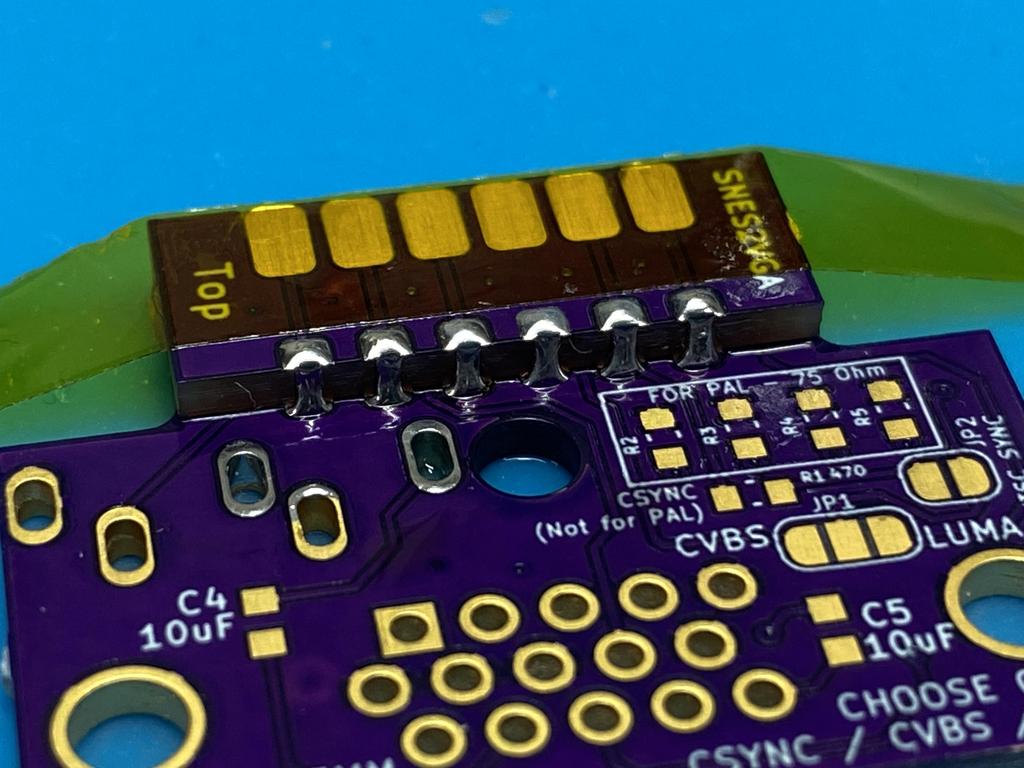
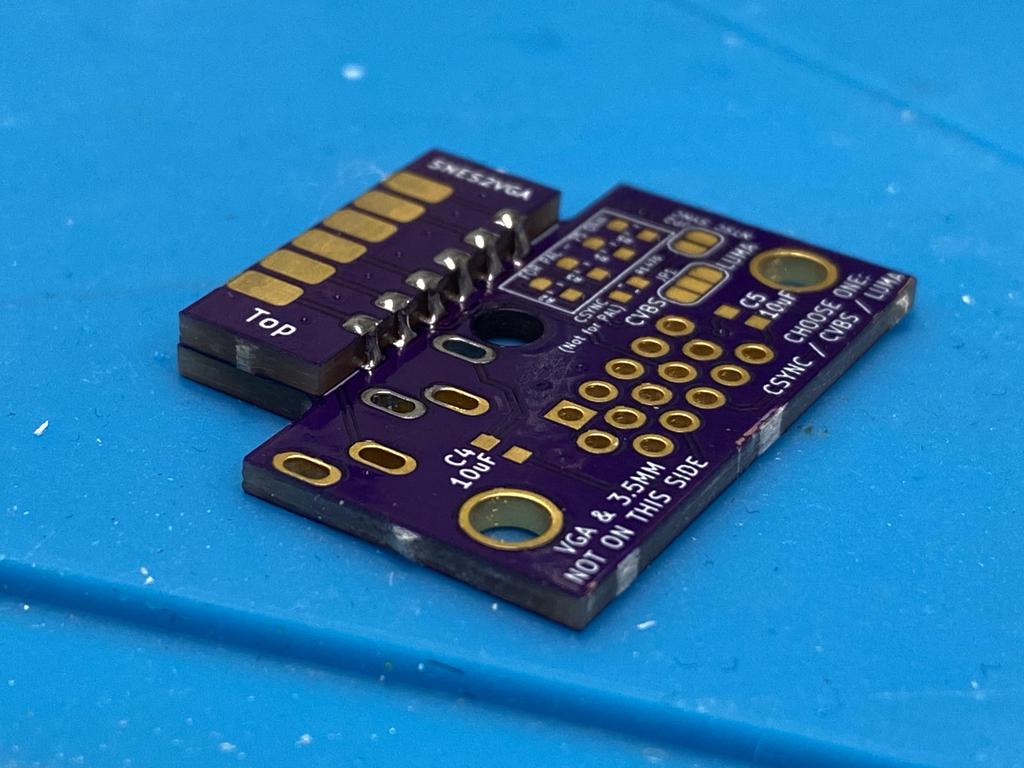
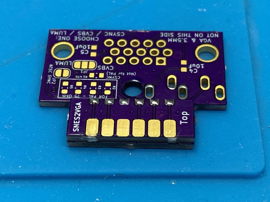
The PCB should be well aligned on all sides:
Multiout connector #
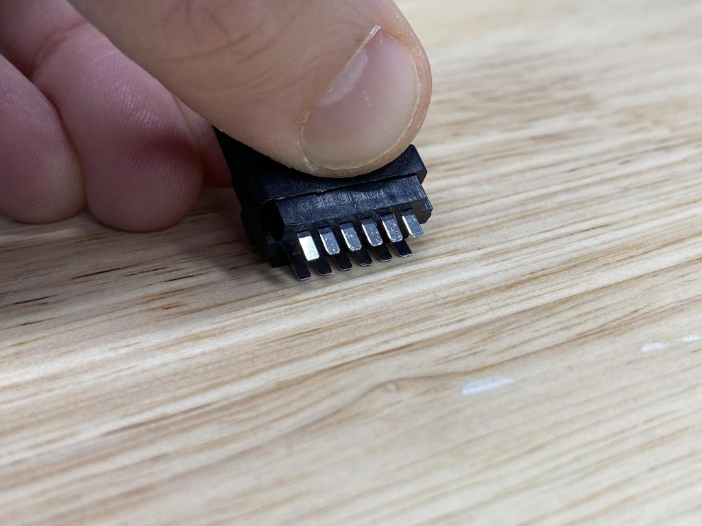
Next up was soldering the multiout connector:
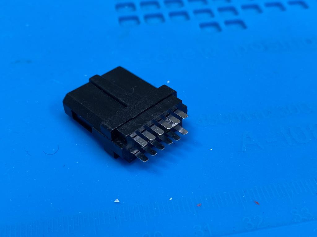
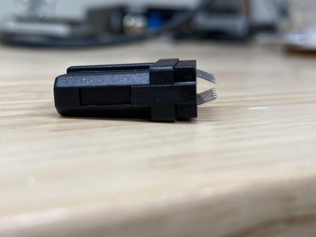
First, I bent the pins down towards each other using the edge of a table:
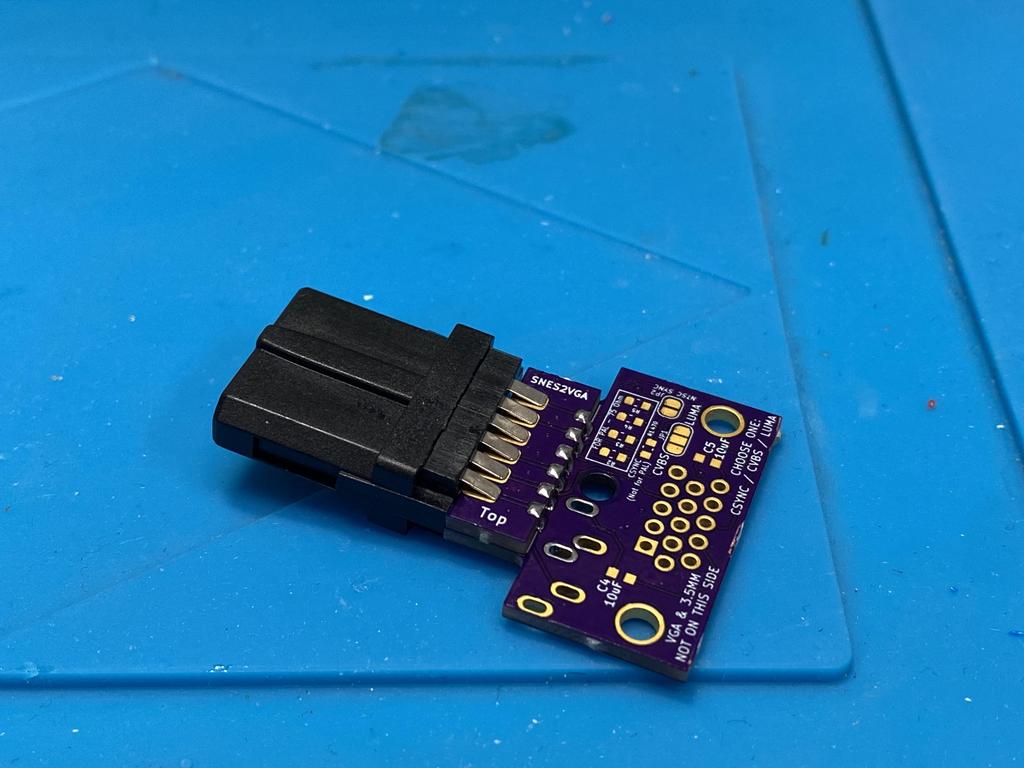
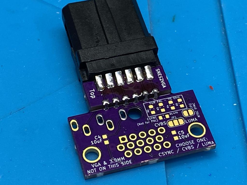
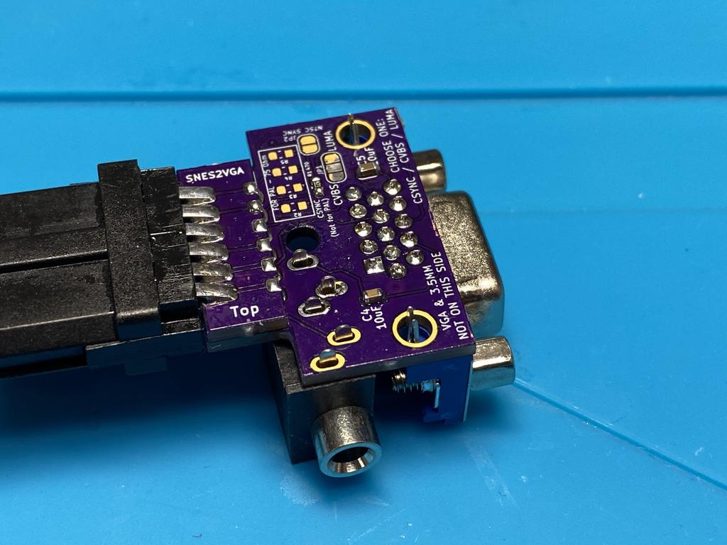
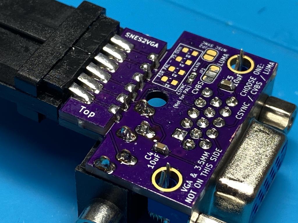
Then I wedged the PCB into the connector, making sure the notched side of the connector is oriented towards the “Top” of the PCB:
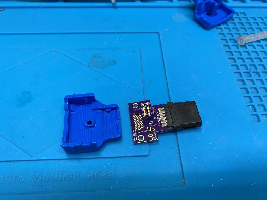
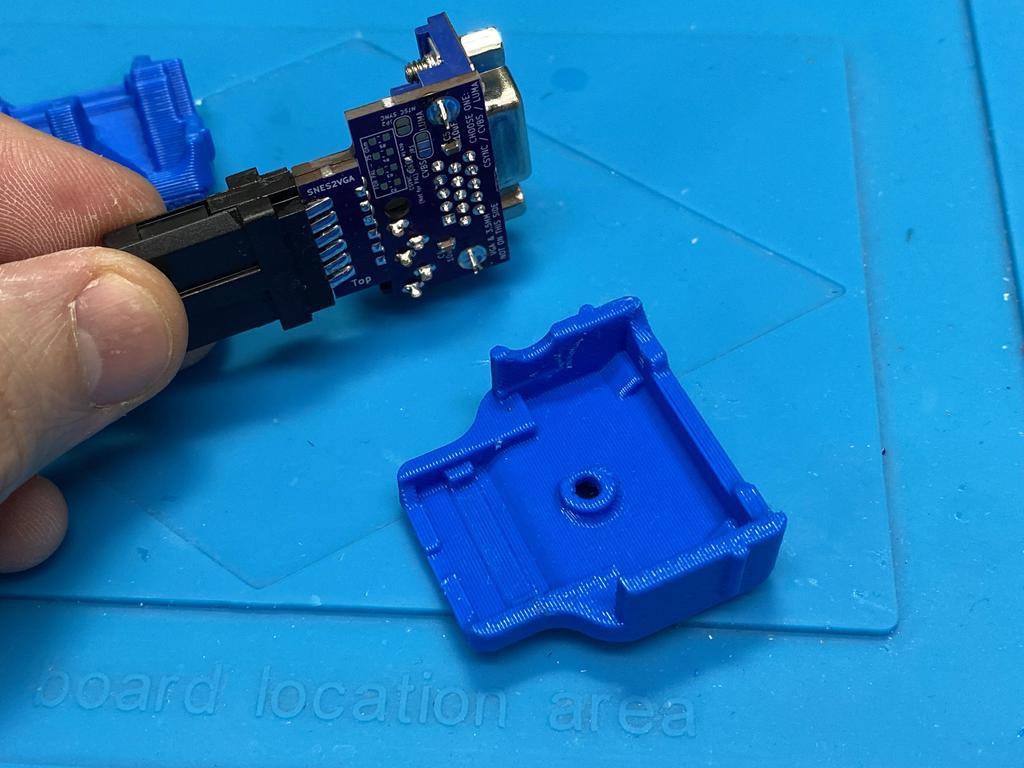
Before soldering, I inserted the PCB and connector into the top shell to make sure everything was perfectly aligned:
While in the shell, I soldered the exposed pins to the PCB:
With that side done, I removed the PCB from the shell, and soldered the pins on the other side:
SMD components #
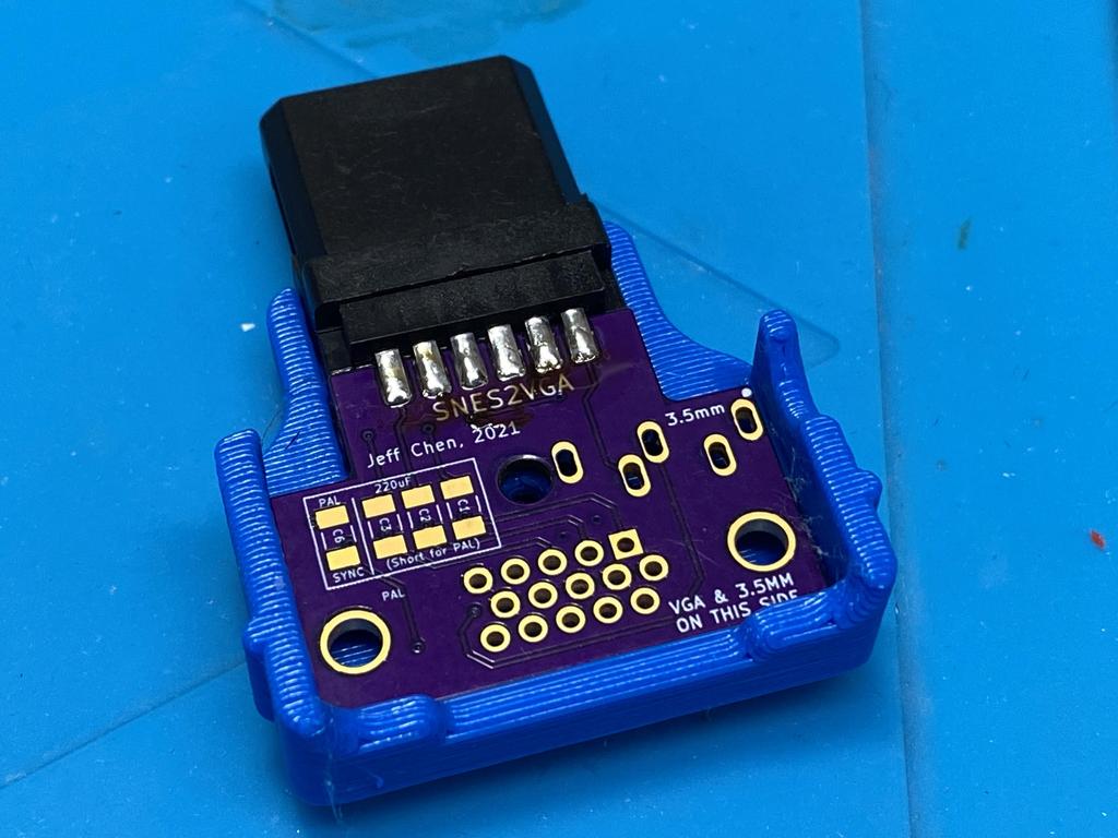
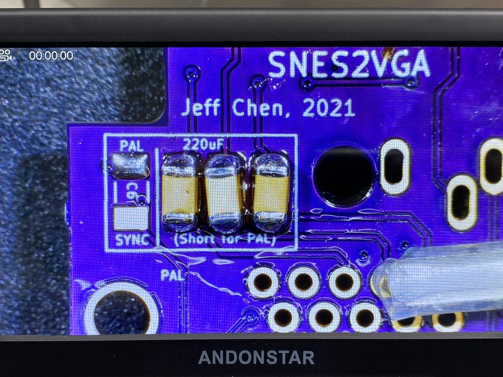
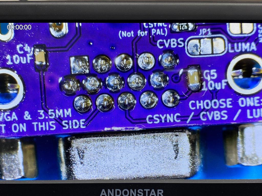
Next, I soldered the three 220uF capacitors to C3, C4, and C5. These coupling caps filter out any DC signal so that only the AC color signal (RGB) passes through:
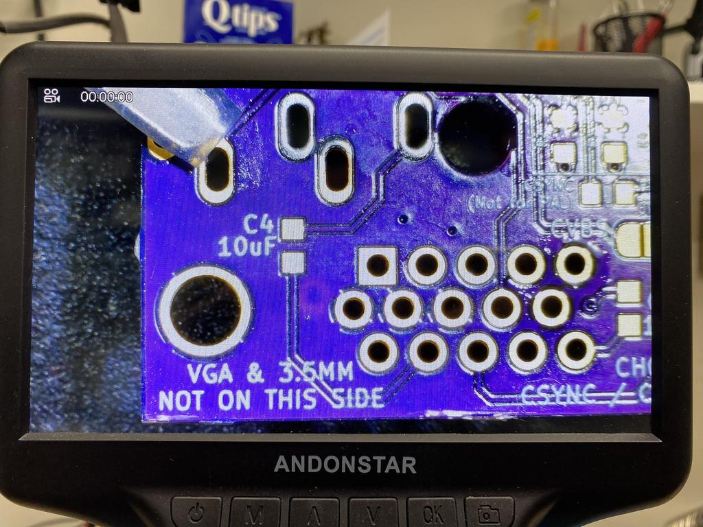
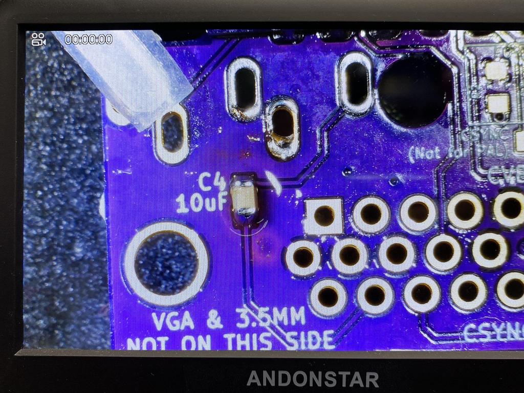
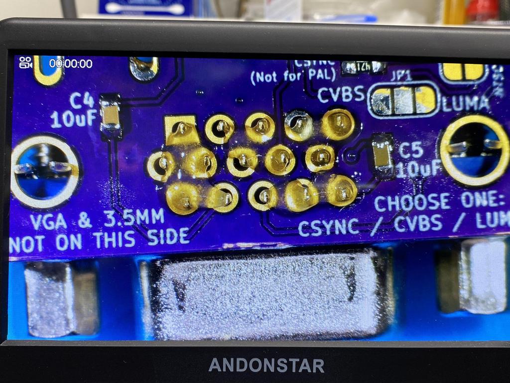
Next, I soldered the two 10uF capacitors to C4 and C5. These connect the left and right audio signals to VGA output pins 12 and 15 respectively. These DC-decoupling caps protect the equipment on the other end if they’re incompatible with these signals:
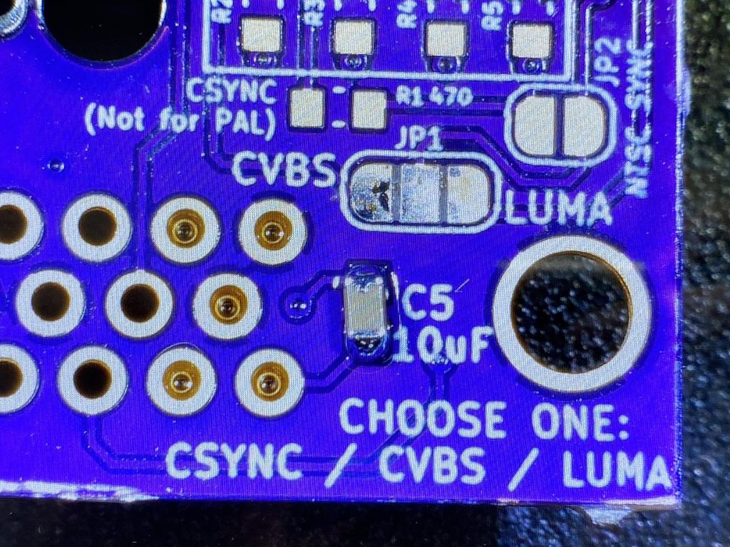
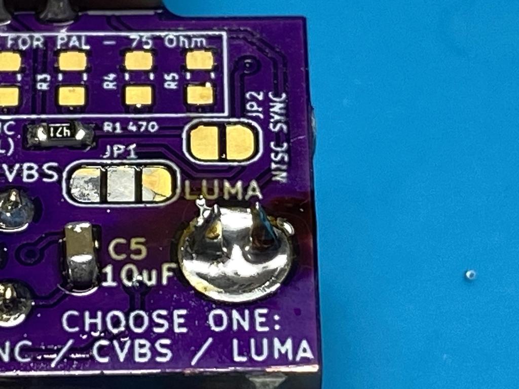
As I decided to use the CSYNC signal for sync, I soldered a 470 ohm resistor to R1. This resistor attenuates the TTL CSYNC signal to what most input devices expect:
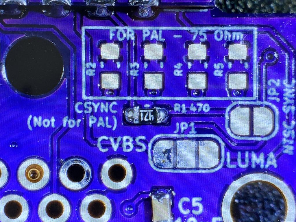
Note that instead of CSYNC, you can also either enable sync on composite (CVBS) or on luma by soldering one of the pads to the center JP1 pad in the picture above, along with shorting J2.
VGA connector and headphone jack #
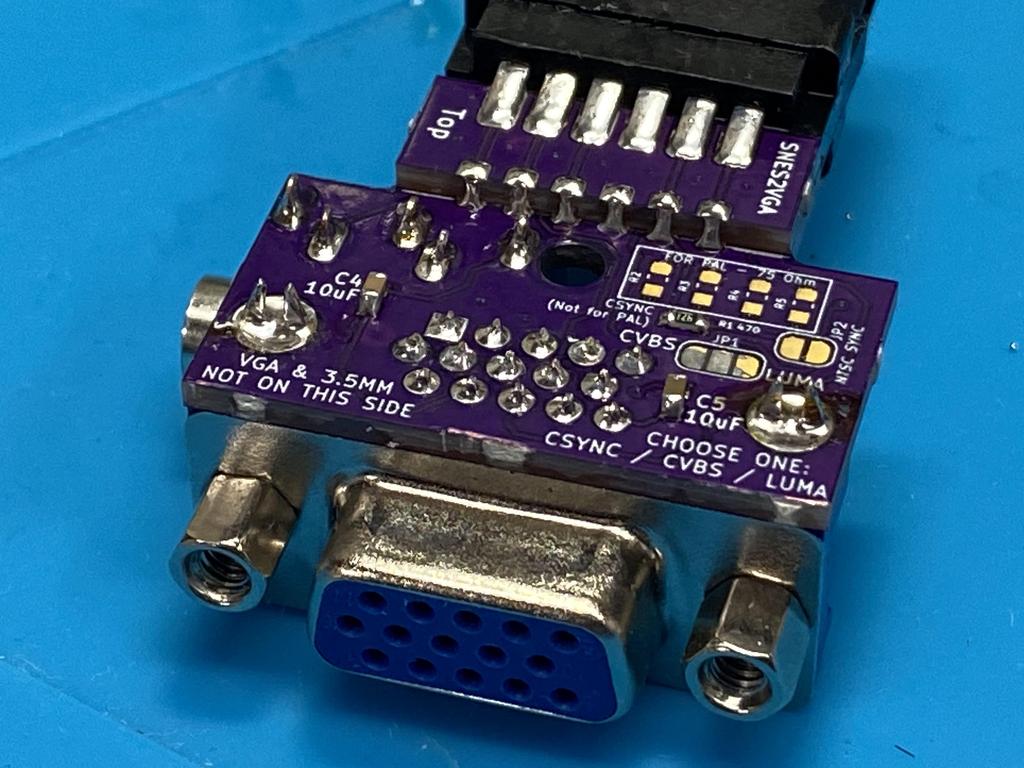
Next up was soldering the VGA connector:
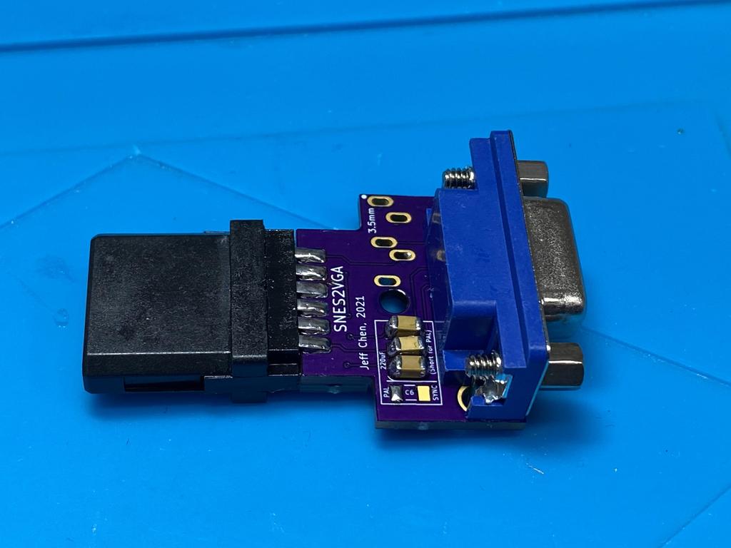
Then the headphone jack:
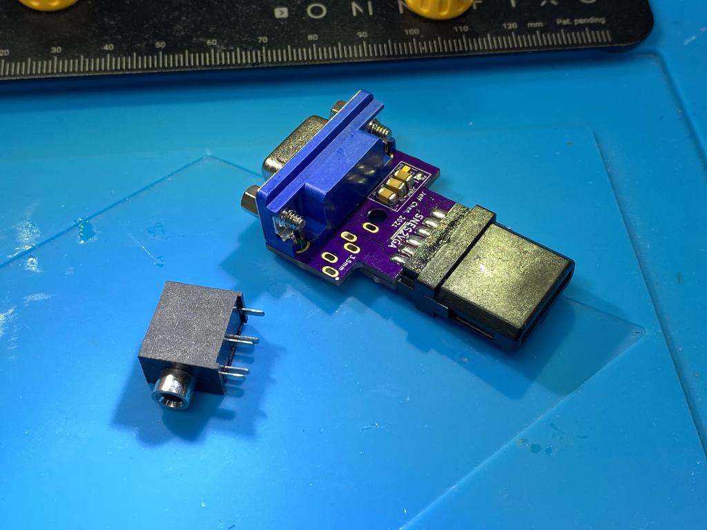
I had almost forgotten to solder in the VGA ground anchors:
Shell #
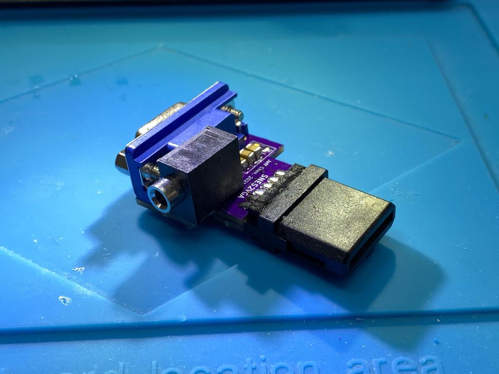
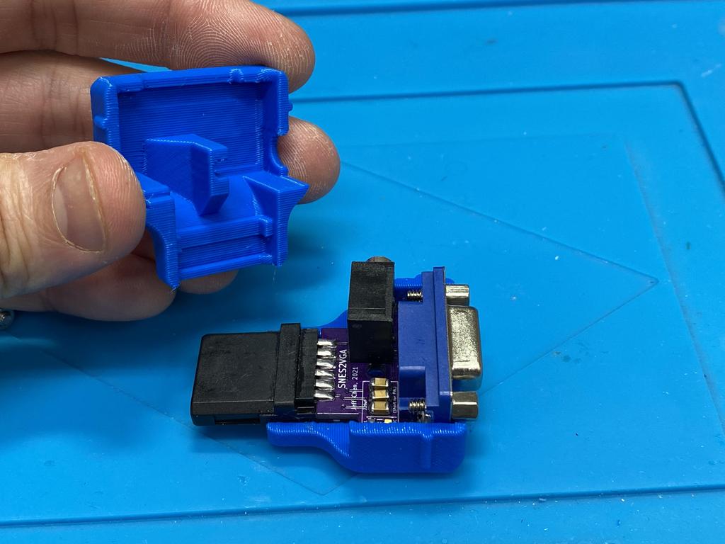
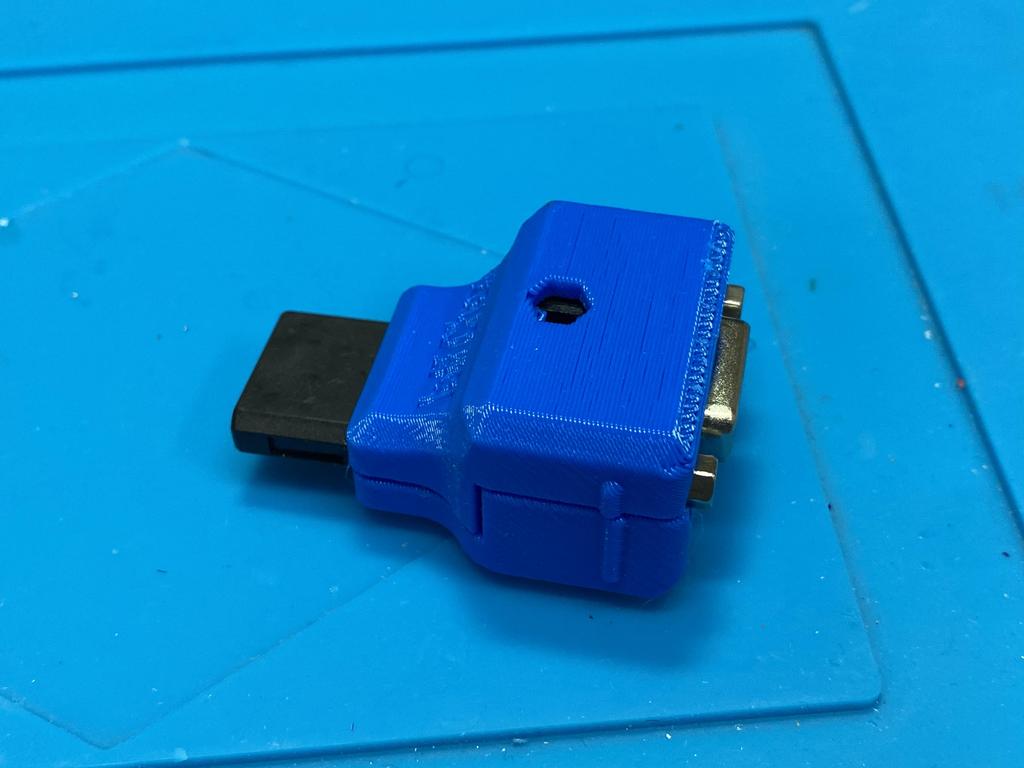
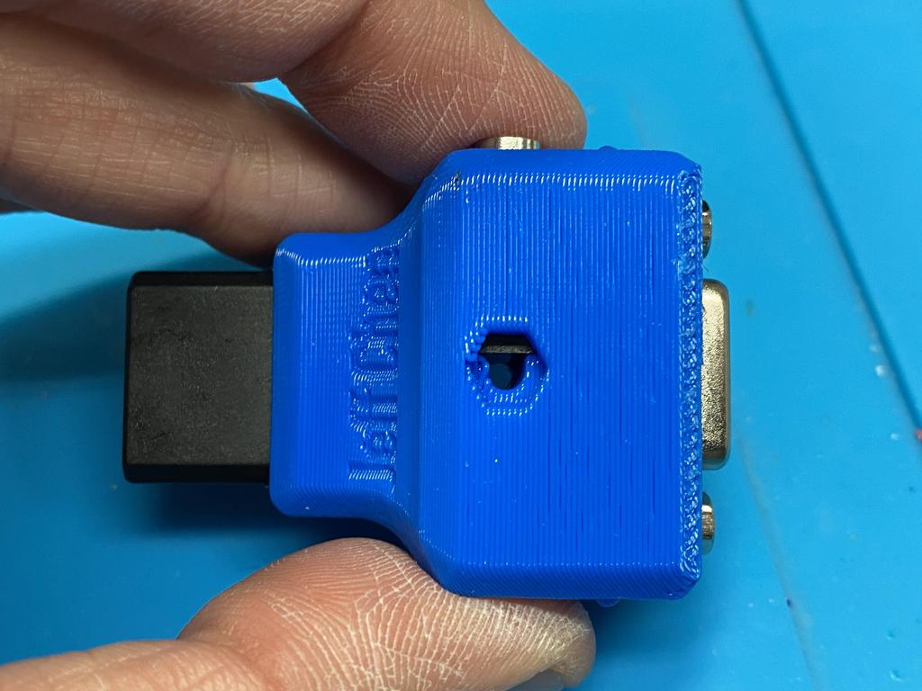
Finally, it was time to put it all together into the shell:
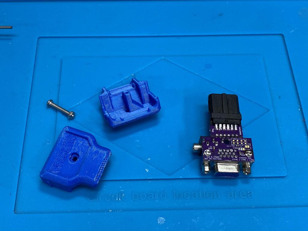
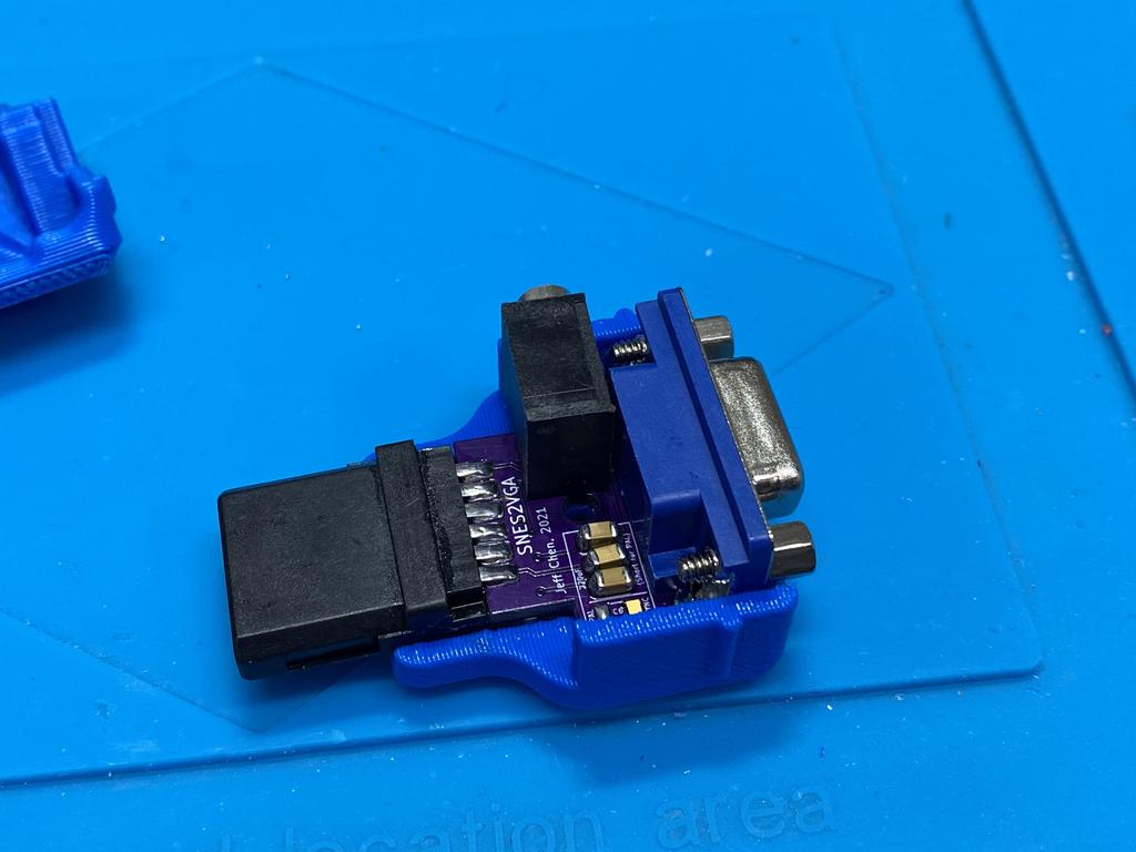
Fitting the top was a little challenging, as there isn’t much room in the shell, but eventually it all came together:
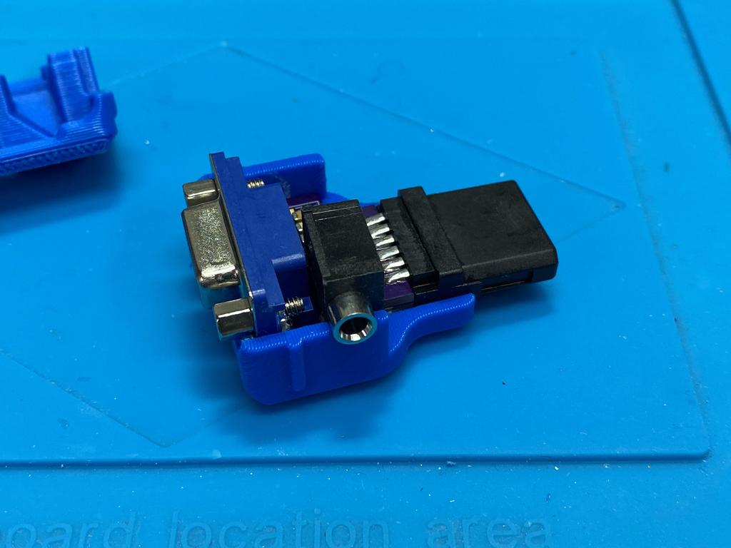
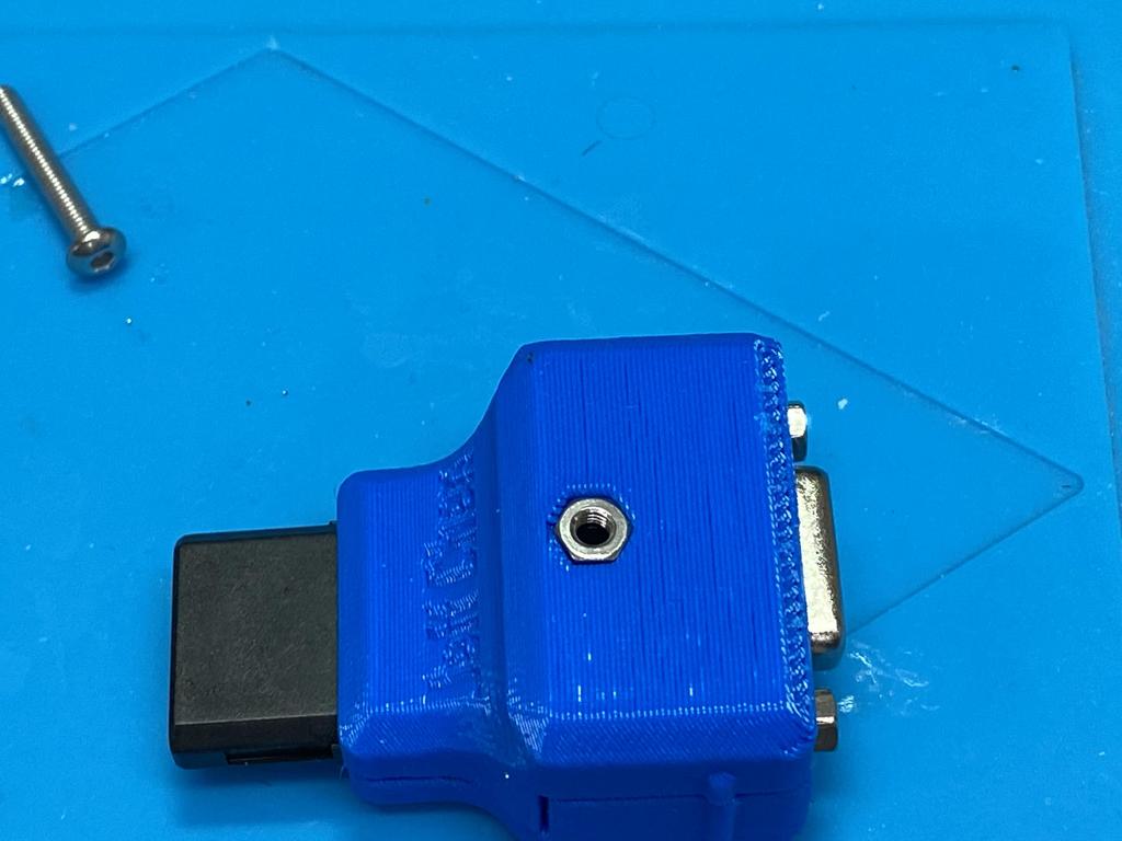
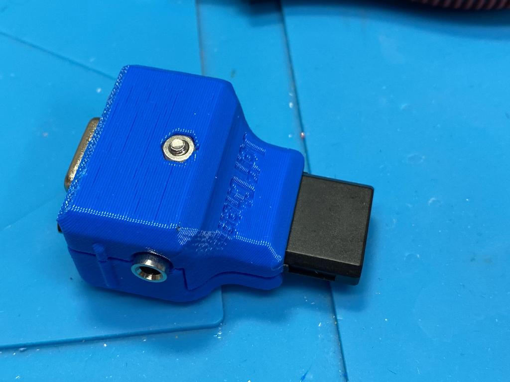
I popped in the nut:
Then pushed the screw through the other side, and tightened it up:
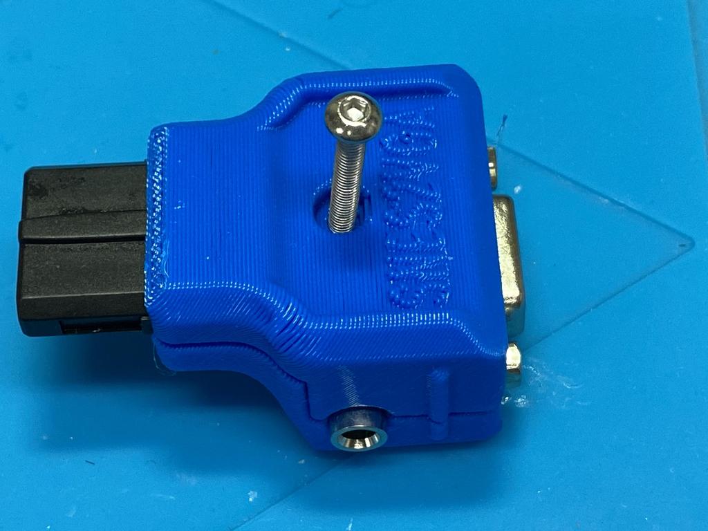
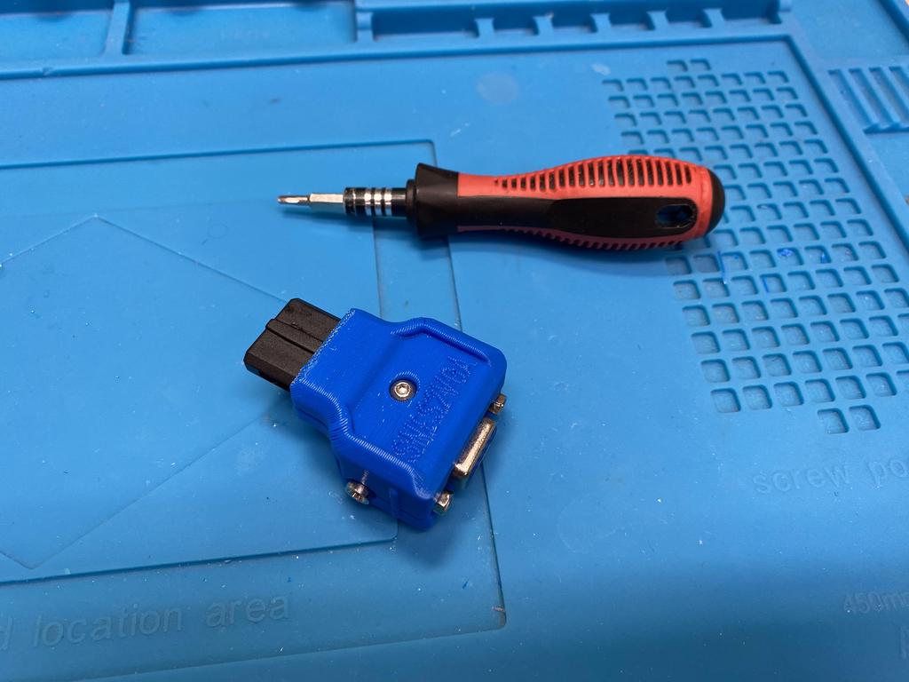
All done!
Testing #
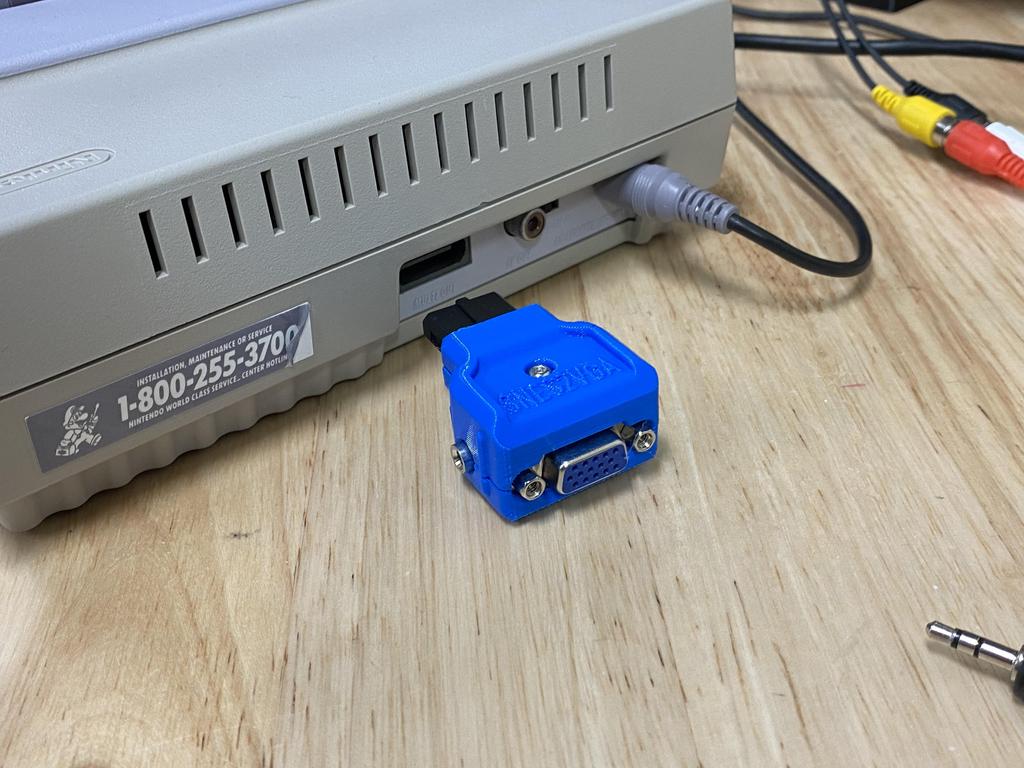
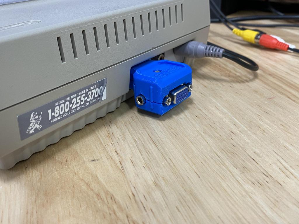
The dongle inserted easily into the back of the SNES:
I connected a standard VGA cable, along with a headphone to RCA splitter:
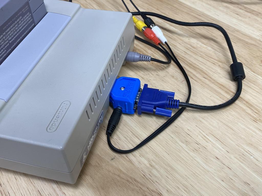
With the other end of the VGA cable connected to my gbs-control, and audio directly to my TV, everything worked perfectly:
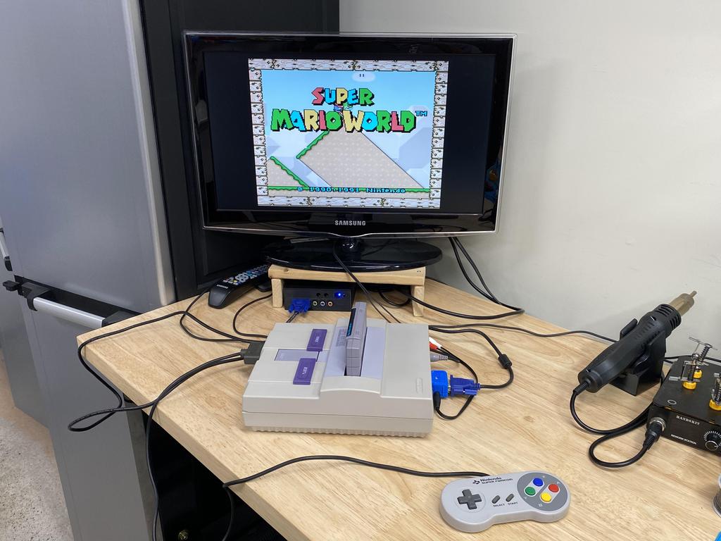
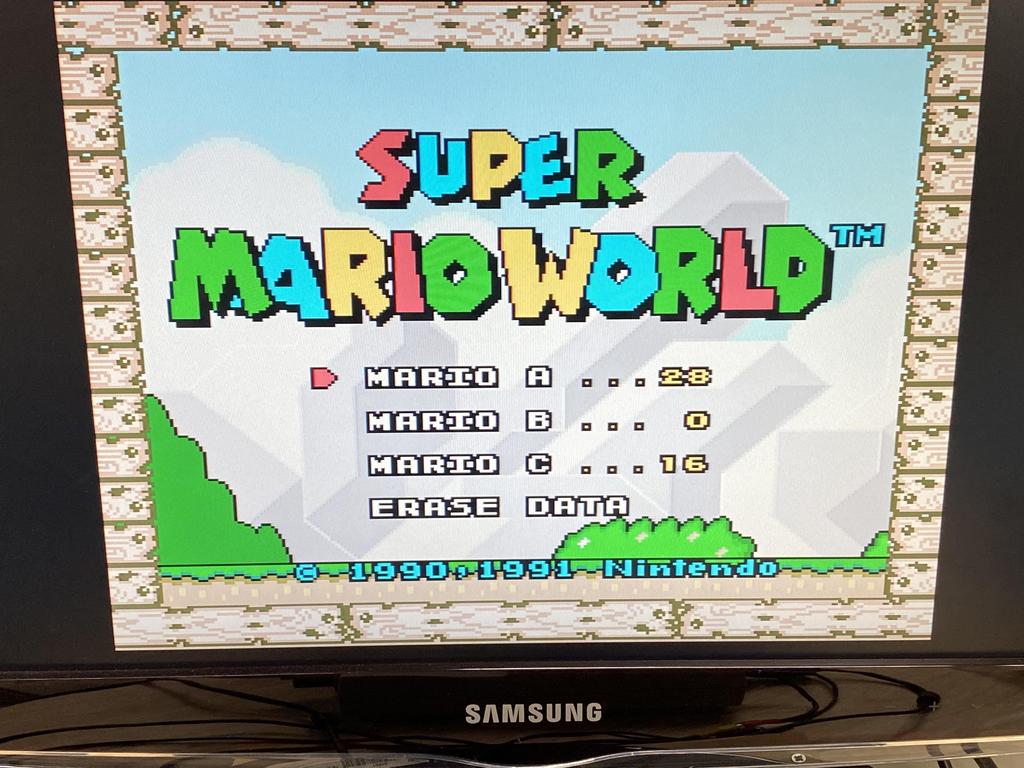
The video quality is at least as good as it was with my custom cable, although probably better:
3D Printing #
Before ending this post, I wanted to share my experience 3D printing the shell. I tried three different ways to print them, each with its advantages and disadvantages.
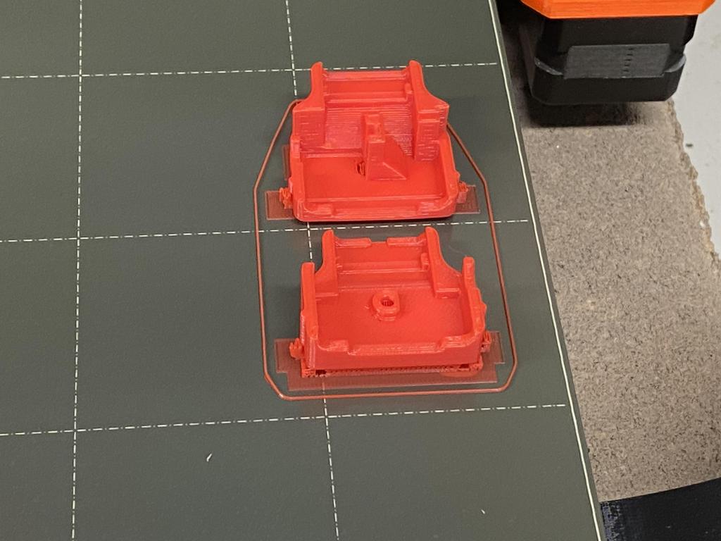
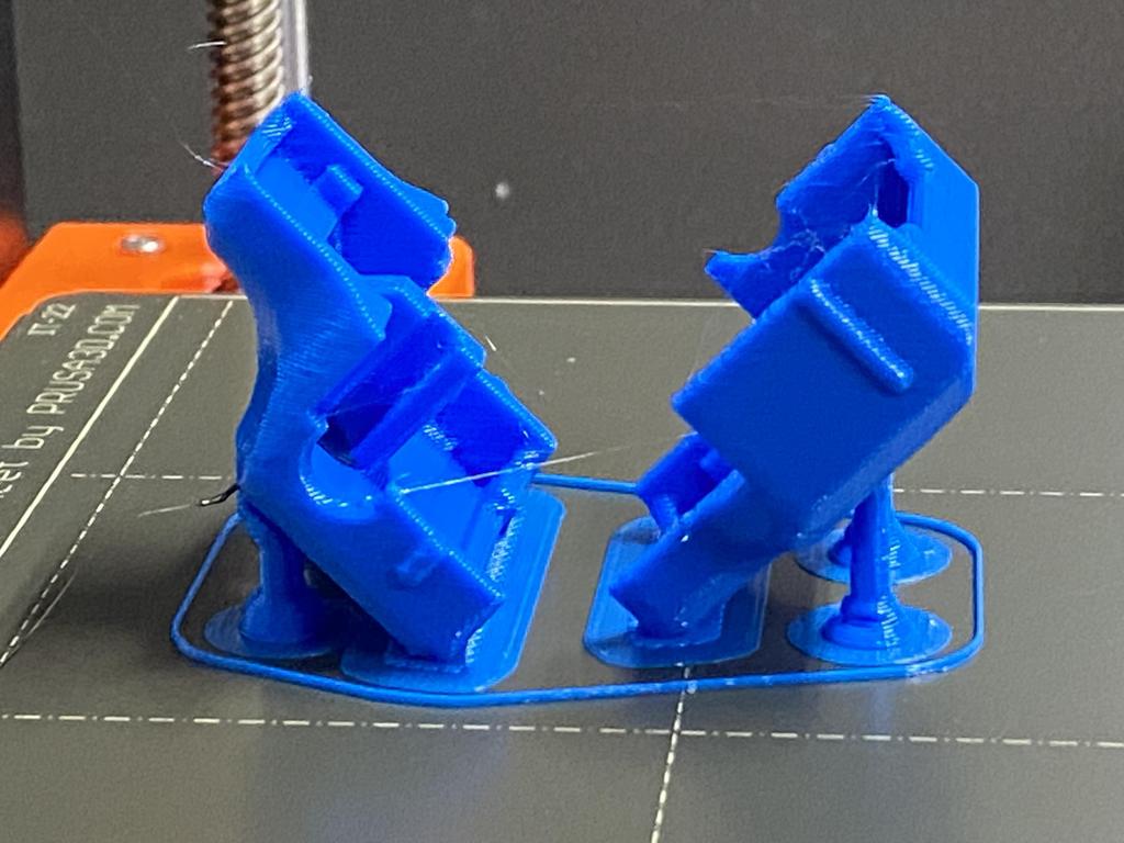
Officially, Jeff recommends printing the top and bottom shell with the split face facing downwards, with full supports enabled. I tried this first:
Removing the supports took a long time:
After removing supports, the inside wasn’t great:
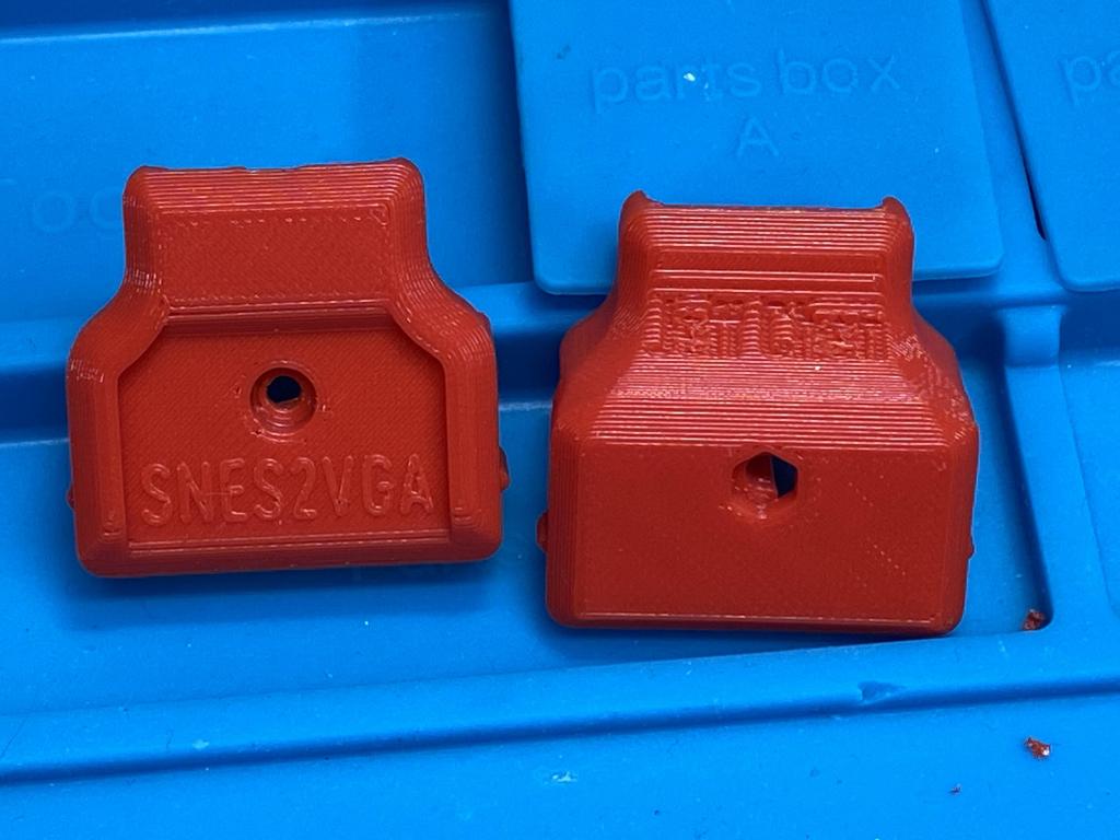
But the outside was perfect:
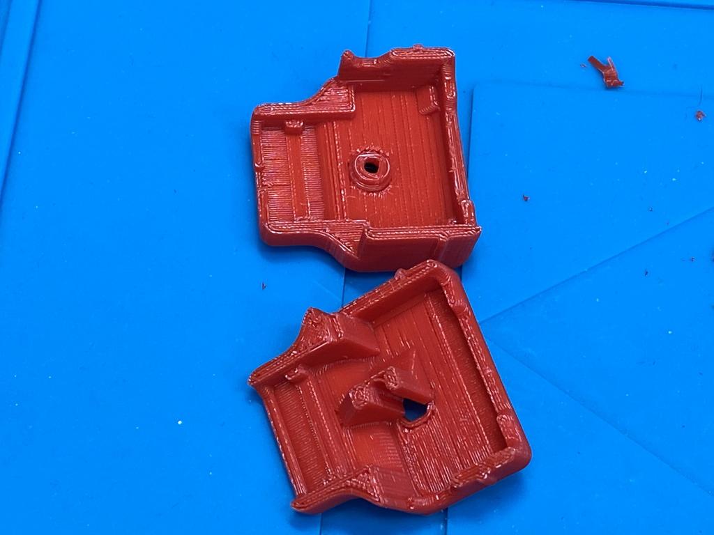
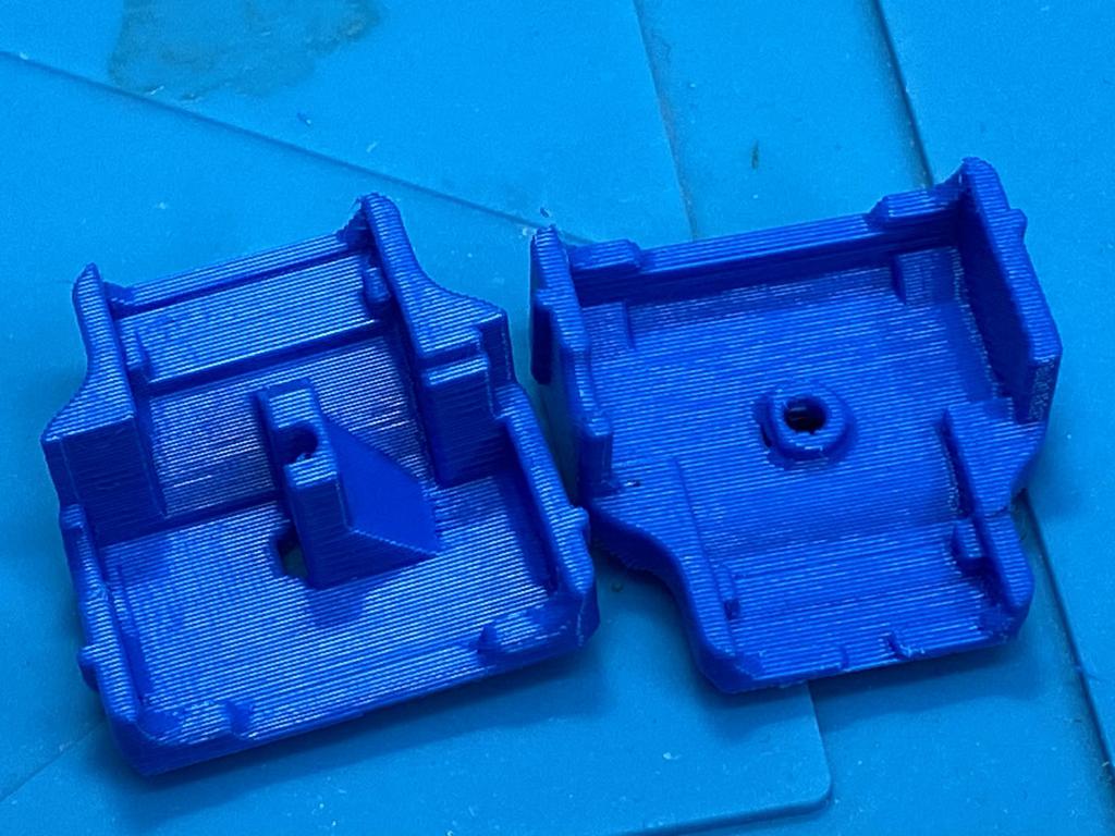
Next, I tried printing with the outside faces facing downwards:
There were a lot less supports, and they were easier to remove:
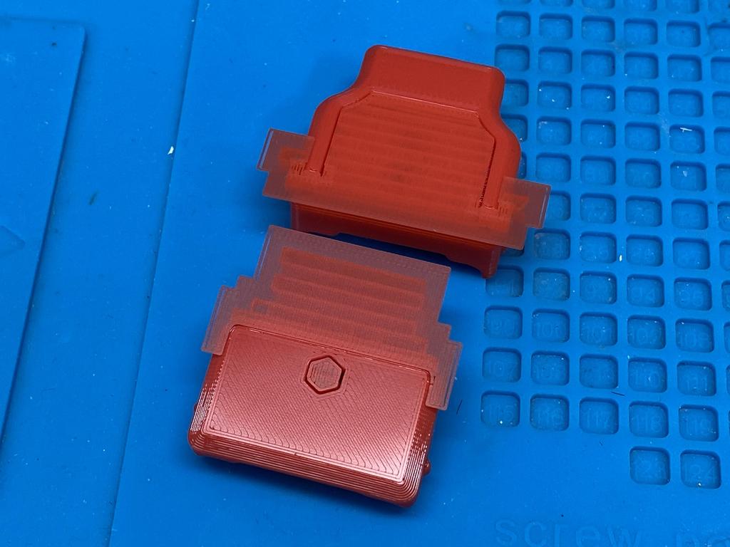
I’m missing a pic of the inside, but as expected, printing this way made the inside perfect. However, the outside looked less good:
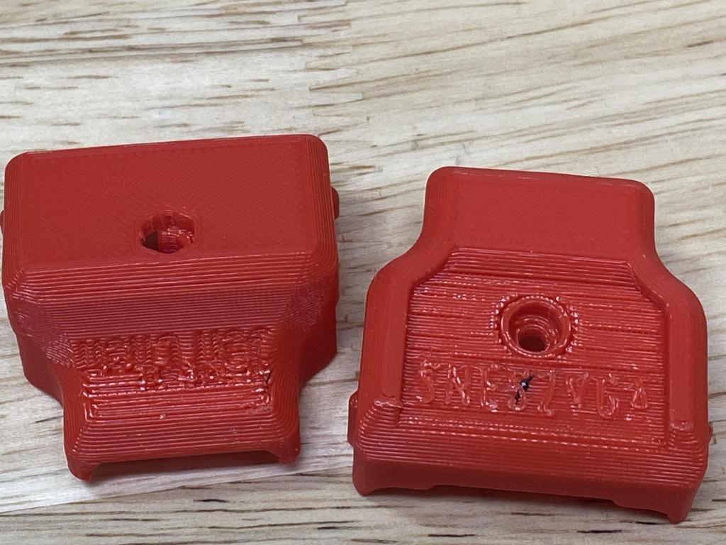
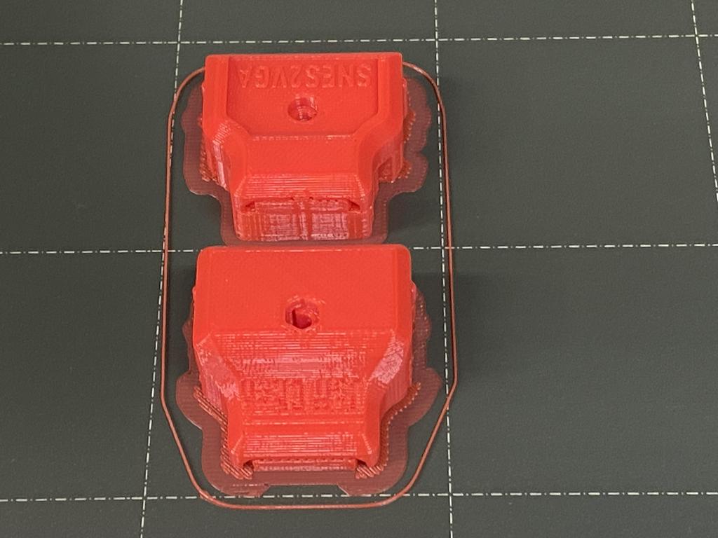
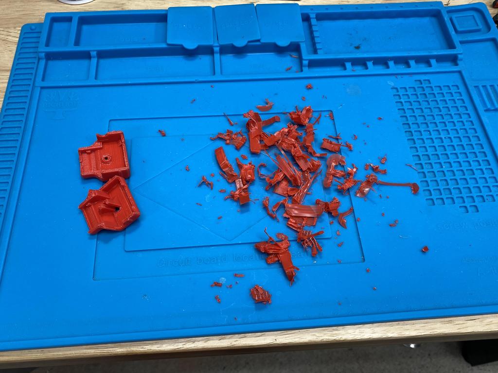
Finally, after discussing with some folks in the RetroRGB Discord (thanks SeeThruHead and cray.io), I tried placing them on one of the diagonal faces with minimal tree supports:
The supports came right off:
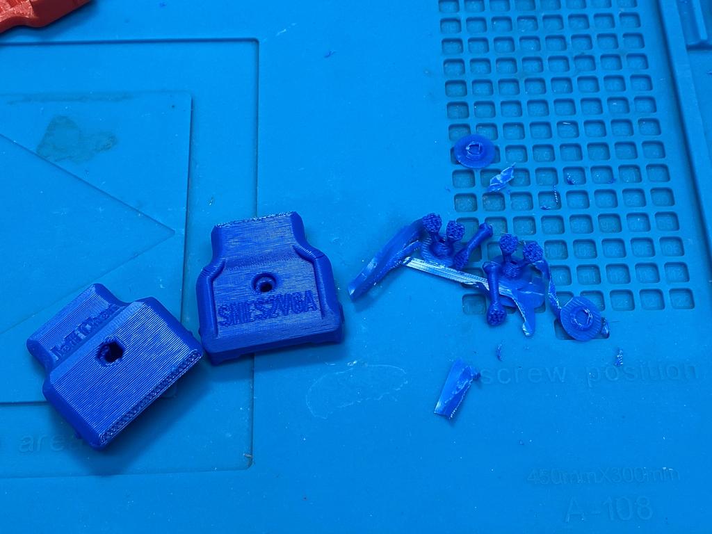
The result was pretty good, and is what I used in this post:
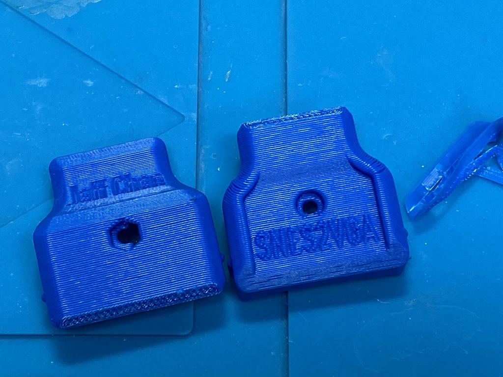
Although this last option was very easy to clean up, and looked pretty good, printing at an angle did create some minor distortions that may have made fitting the assembled PCBs inside a little more challenging. Next time, I would try this again, but instead of using 0.3 mm layer heights as I did, I would try 0.2 mm or 0.1 mm.
Thoughts #
Overall, I think this project is really great! Jeff’s design is very well done: it’s both compact and versatile, supporting NTSC and PAL, as well as different sync methods. I also love that the audio signal is passed through the VGA cable, which is something I intend to take advantage of (stay tuned for a future post on this!).
SNES2VGA is actually part of a larger series of Console VGA Dongles that Jeff has designed. Personally, I think going the route of using VGA for all my old consoles makes a lot of sense because VGA cables are cheap, and many scalers support it, and there are some pretty cool VGA switches out there, like the Extron MVX ones.