Lava RGB
Back in 2021, I installed an NESRGB on a front loader, which has been working great. For years now, NESRGB was pretty much the only mod available to get RGB out of the NES; but recently, a new mod known as Lava RGB came on the scene from a company in China. I bought one, and in this post I go over how I installed it on another front loader.
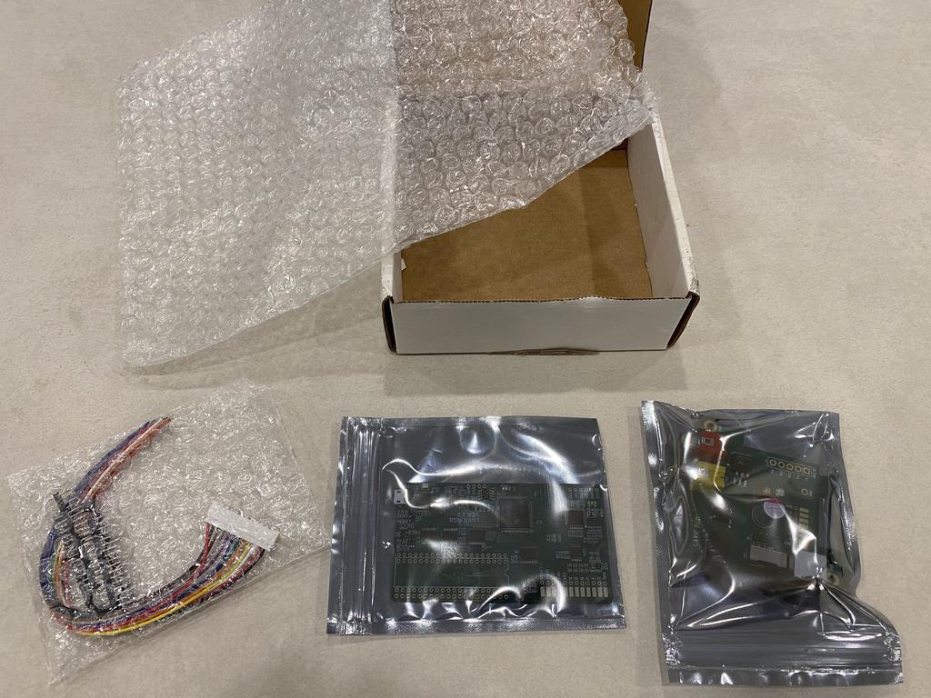
I bought the Lava RGB mod off AliExpress from Lava FC Store, specifically from this listing (although I suspect these links will not survive very long). The “color” I bought is the one named “NES senior VER 2.0”, which includes both the mod board itself, along with a replacement power A/V module. Version 2.0 adds a bunch of new features on top of the previous version 1.2, such as 24-bit color output, 8 integrated palettes, the ability to reset the console and change palettes using controller 1, an OSD that displays the palette name when switching them, and a micro usb port that allows for firmware upgrades in the future.
Compared to the NESRGB, Lava RGB 2.0 is definitely a worthy contender. The palette switching OSD, and ability to easily update firmware, are improvements, and I wonder if future firmware updates might add more OSD-based options. However, one thing Lava RGB does not do is process and output audio like the NESRGB. Although not a huge deal, it does mean audio needs to be tapped from the main audio output circuit. This is probably why the latest version now offers a power A/V replacement PCB which routes audio output to its Saturn-style DIN connector.
Although the power module includes a Saturn-style DIN connector, I don’t own a compatible cable, and prefer to use VGA cables. So for my install, I decided to add a SNES multiout port.
Parts #
- Lava RGB 2.0 mod board and power module - $81.37 CAD
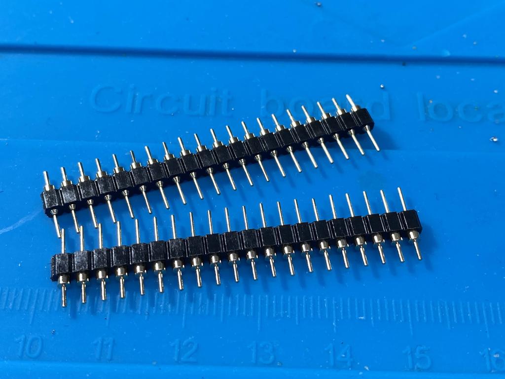
- Two 20 rounded pin headers - $16 CAD for ten on Amazon
- SNES multiout parts (more on that later)
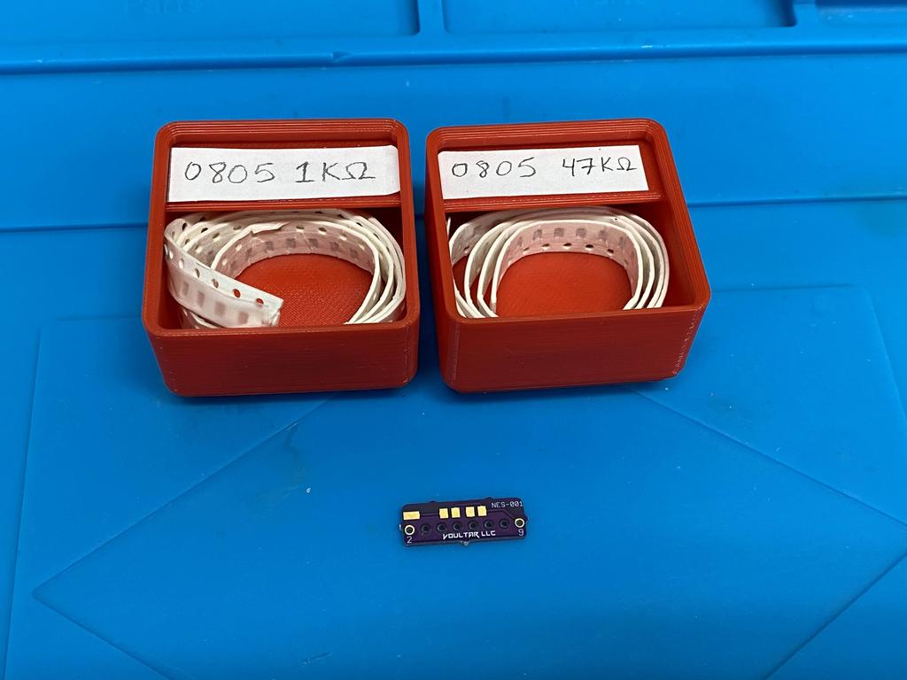
- 47K resistor for expansion audio
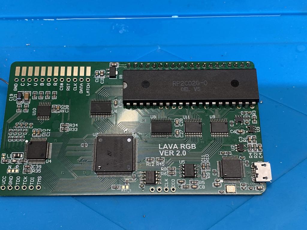
The Lava RGB kit took about a week to arrive, and was packaged decently well:
The Build #
Prepare NES main board #
Remove PPU #
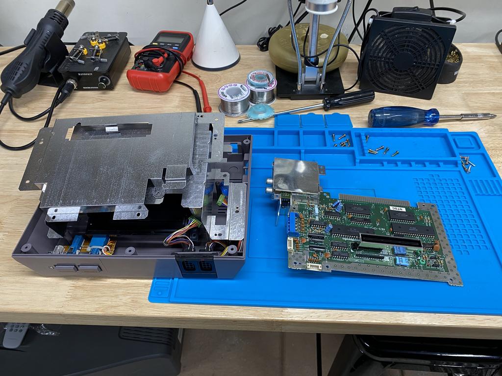
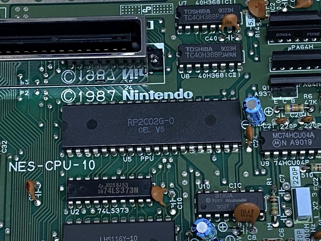
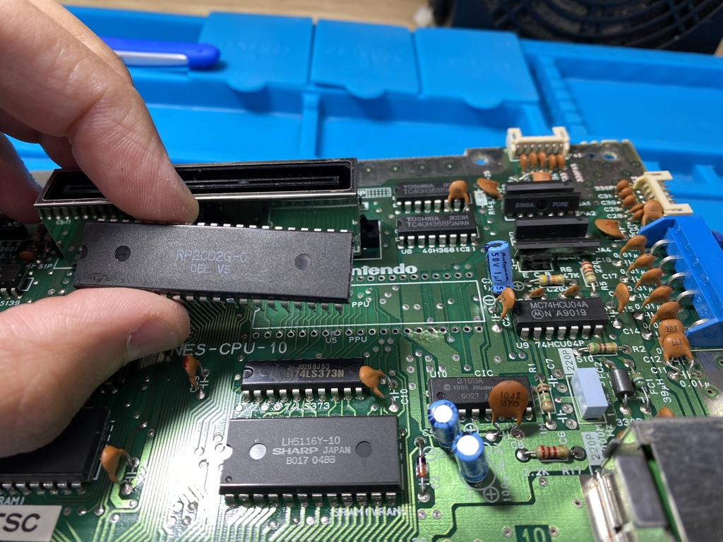
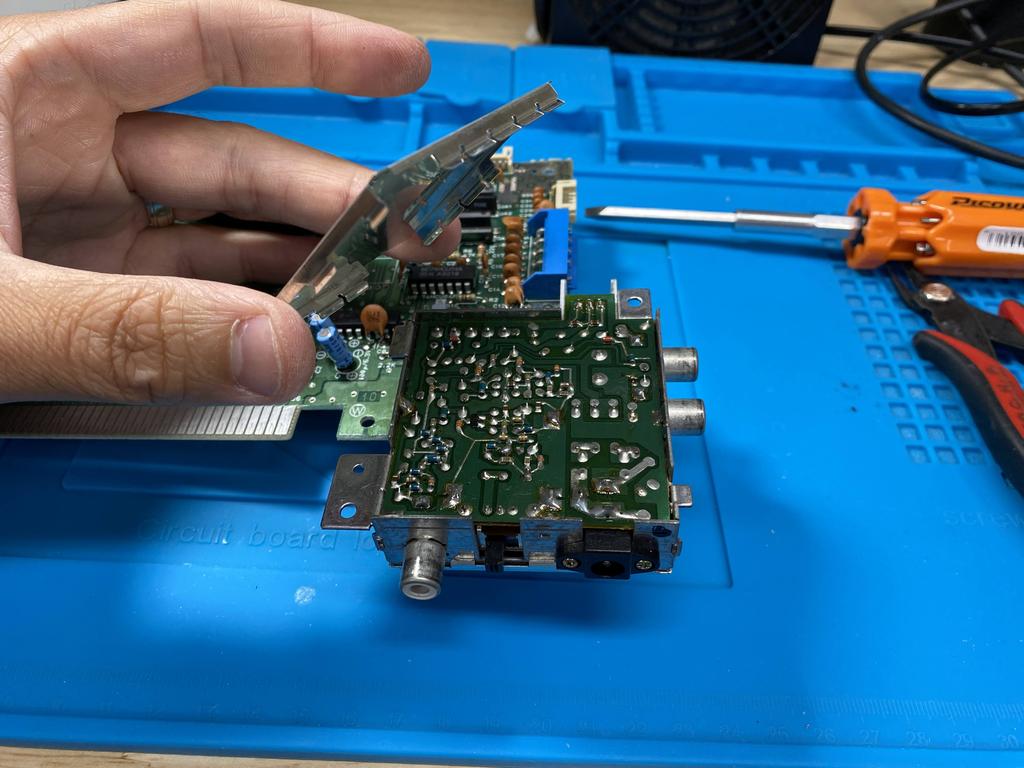
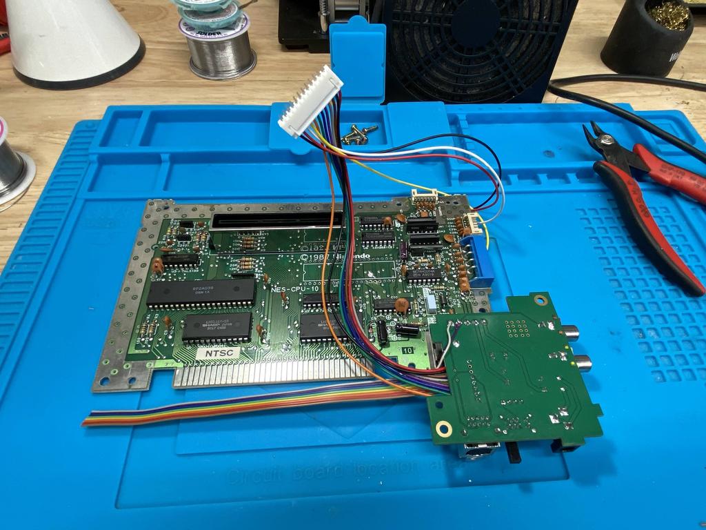
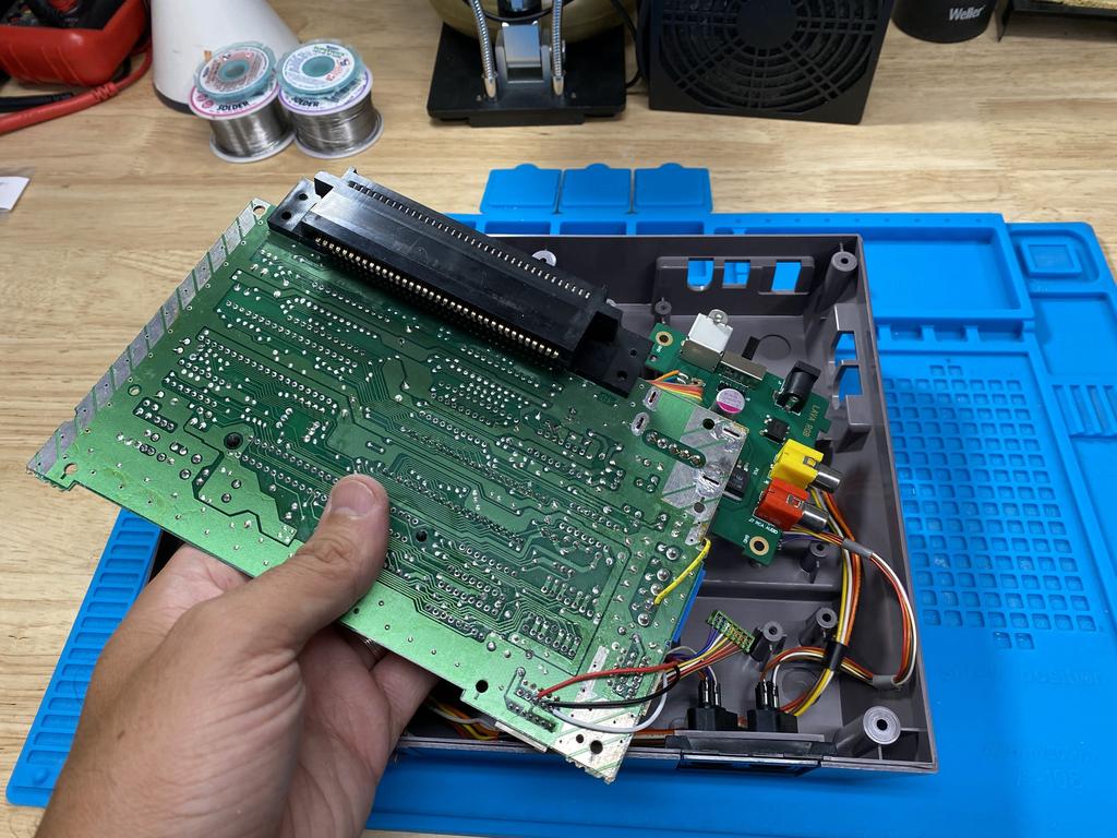
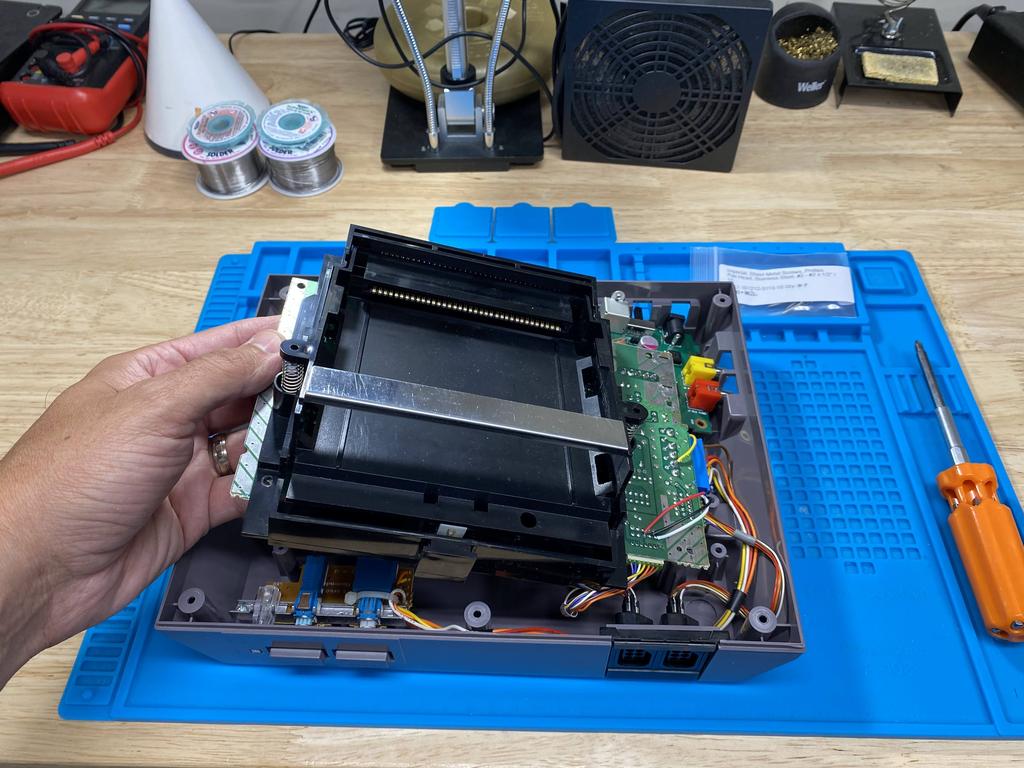
I picked a front loader with an NES-CPU-10 main board that was in excellent shape. I took it apart, and extracted the main board from the shell:
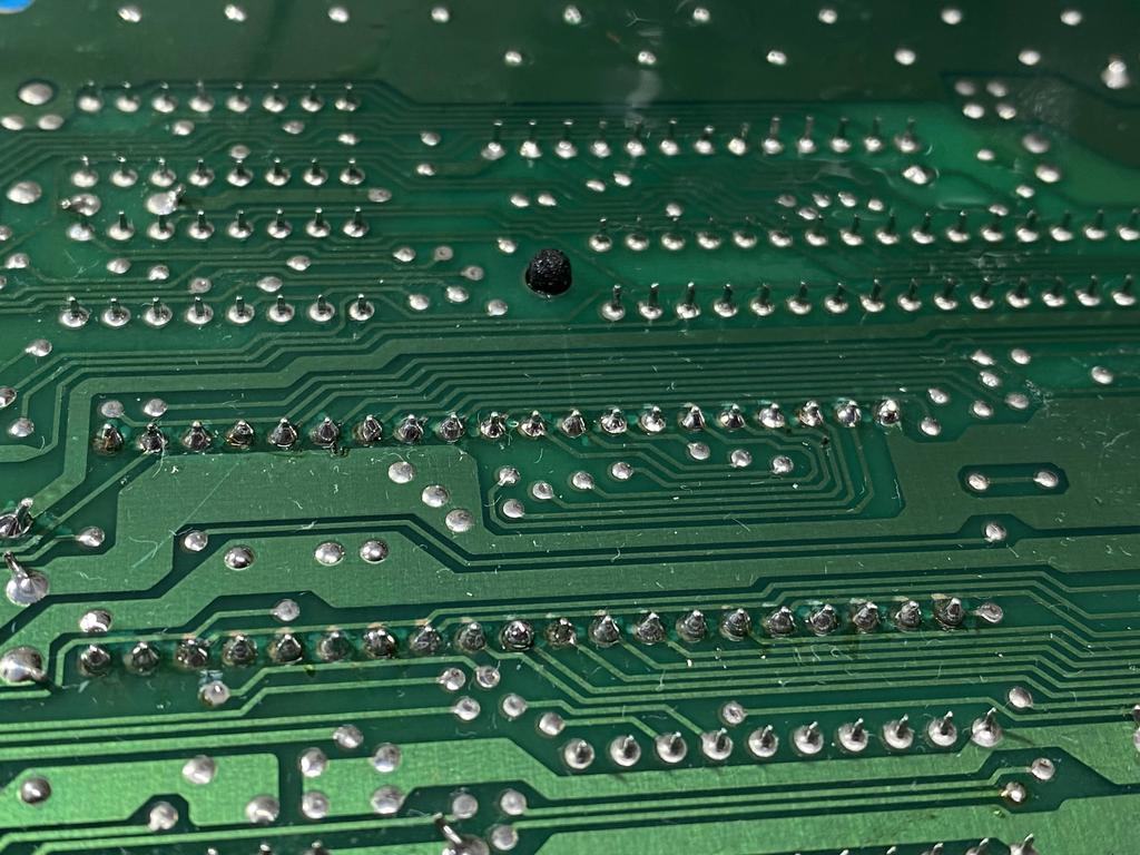
First order of business was to desolder the PPU:
I started by adding fresh solder, using flux to make it flow into the existing solder:
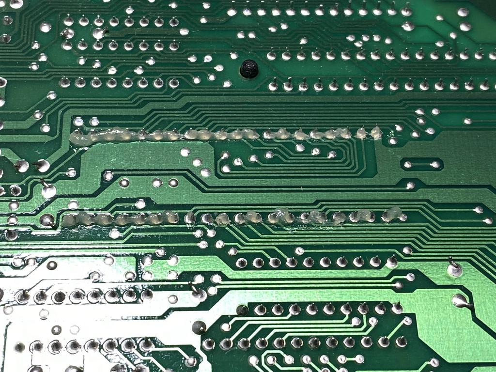
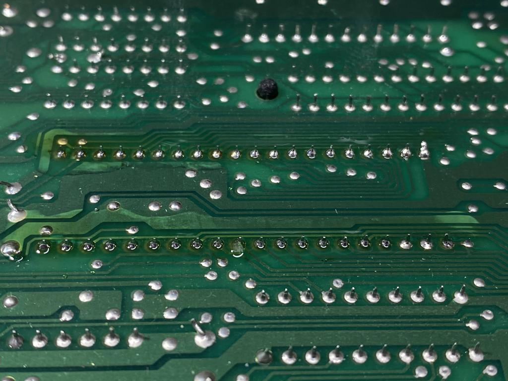
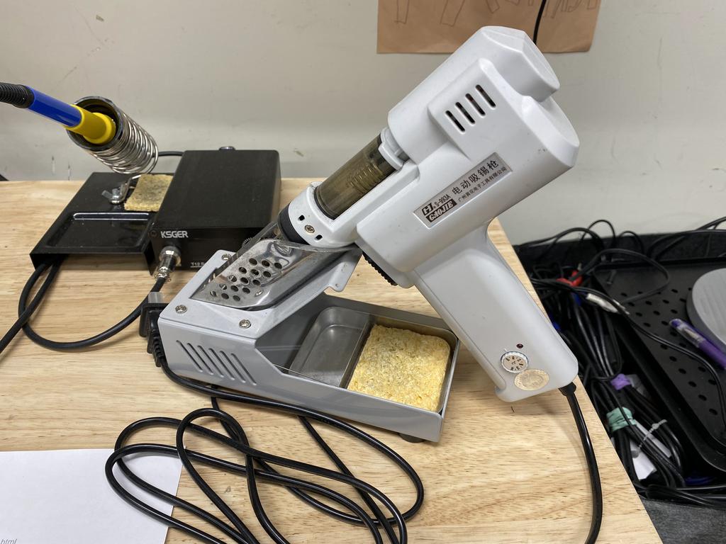
I then used my trusty desoldering pump to remove all the solder from the pins:
Using a trick I learned from Voultar, I used my finger nails to move each pin back and forth until they moved freely. For the usual more stubborn pins on the thicker ground plane, I added more solder and desoldered again until I was able to move the pins. With that, I extracted the PPU:
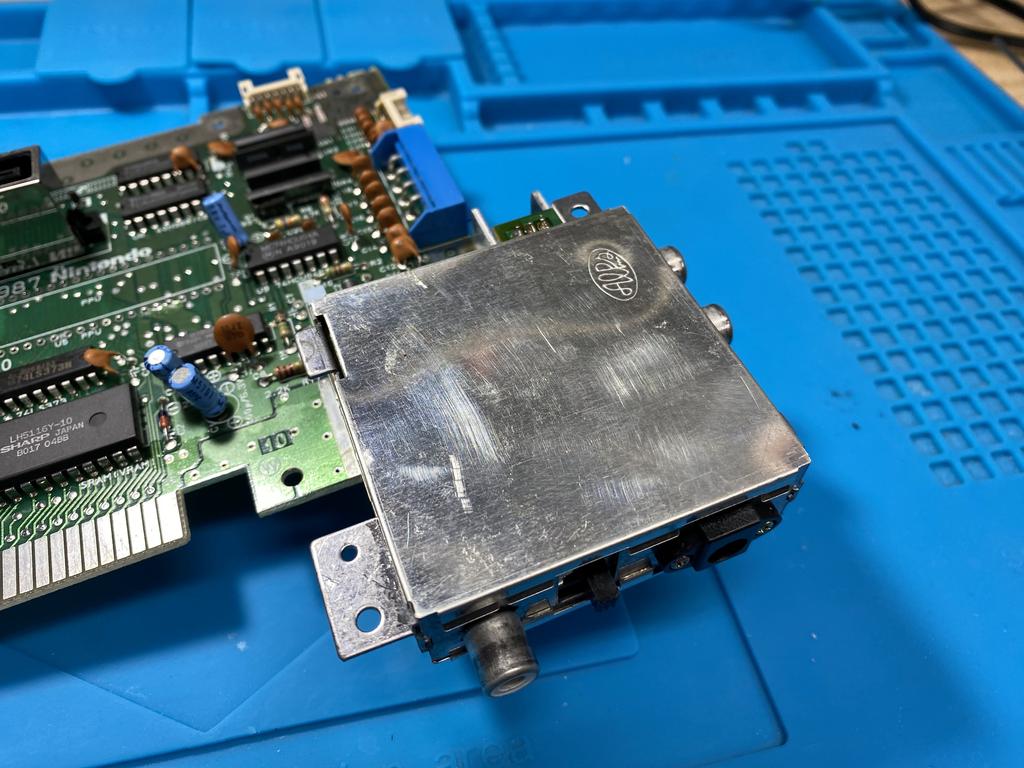
Remove power module #
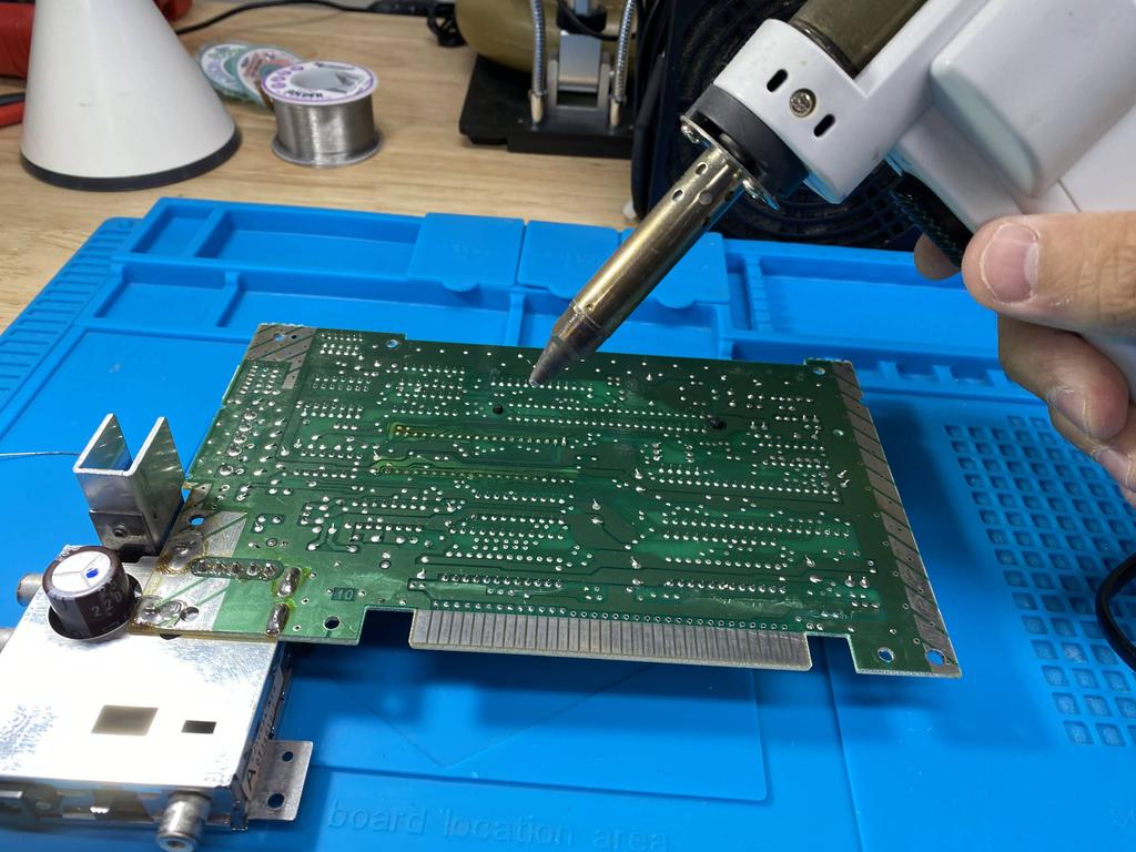
Next I needed to remove the original power module to replace it with the new one:
This can be pretty challenging, but with the right tools and technique, it’s not too bad. I started by adding flux to the four large pins that anchor the power module to the main board and use my desoldering gun to remove most of the solder:
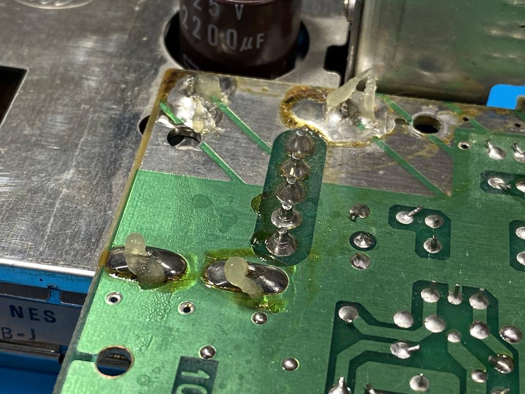
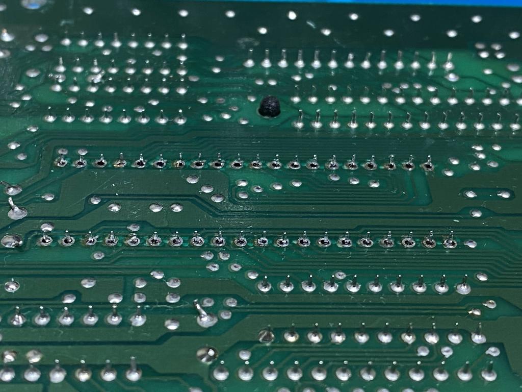
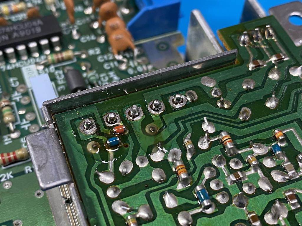
Then I use wicking braid to remove the solder lodged around the pins. I added a little more solder and flux to the pins until I was able to wick away most of the remaining solder:
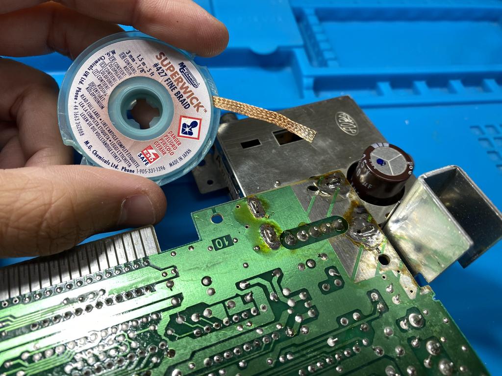
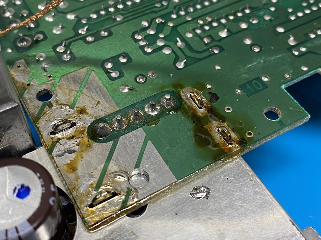
At this point, the gaps around the pins are pretty clear:
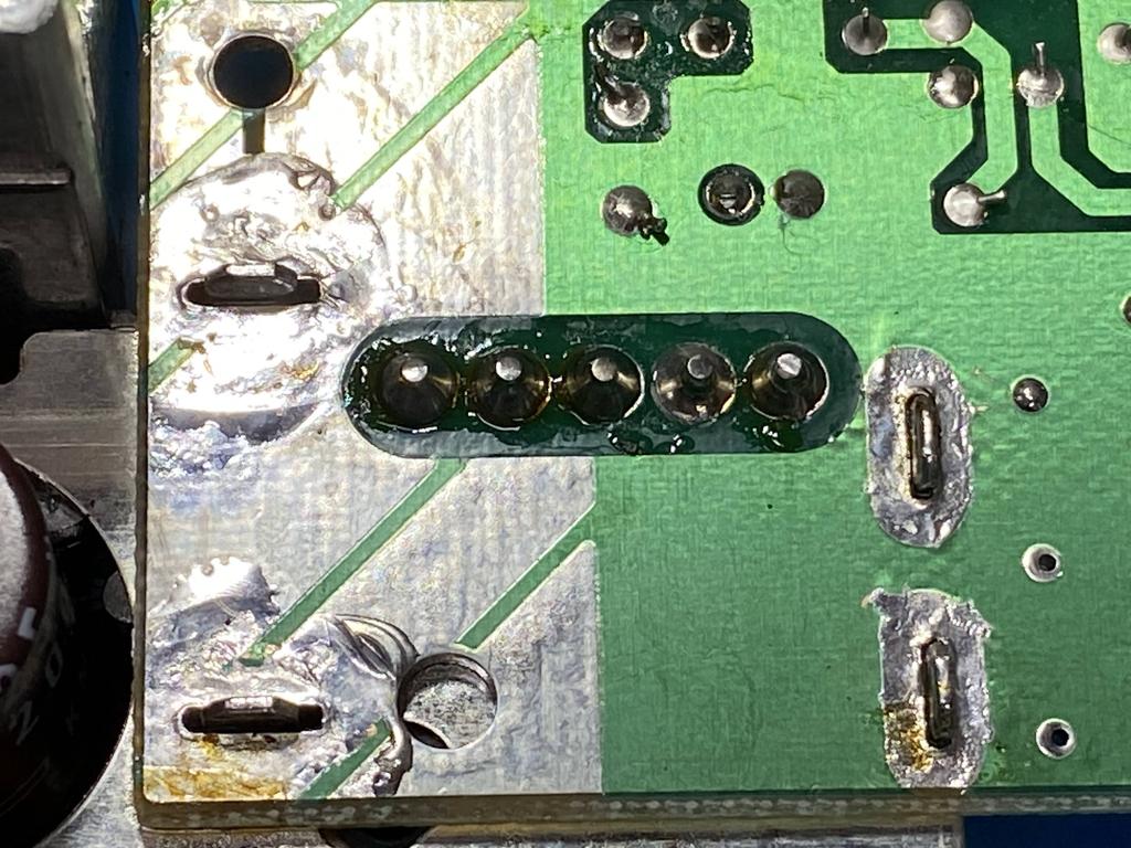
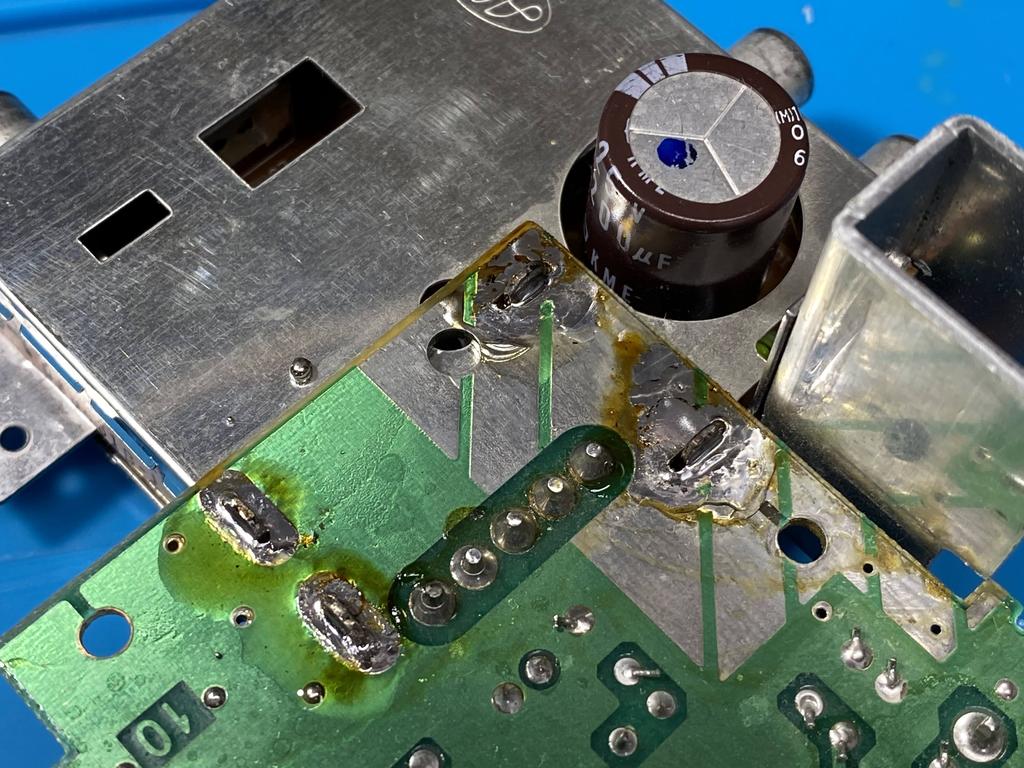
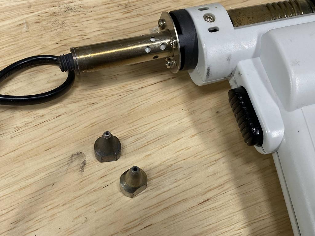
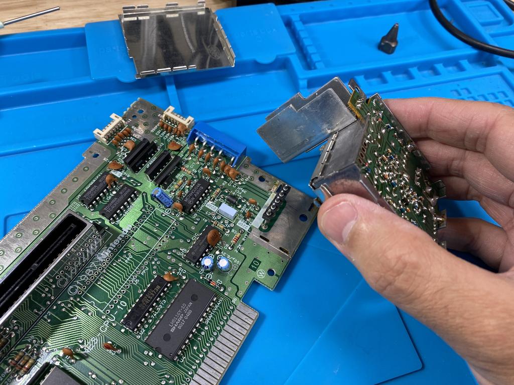
The next trick is to desolder the 5 pins visible above - but not from this side, but rather from inside the power module. This is actually necessary for properly installing the new power module that comes with the Lava RGB kit. I pried off the metal plate:
I switched tips on my desoldering gun to one with a larger pitch, and desoldered the 5 pins:
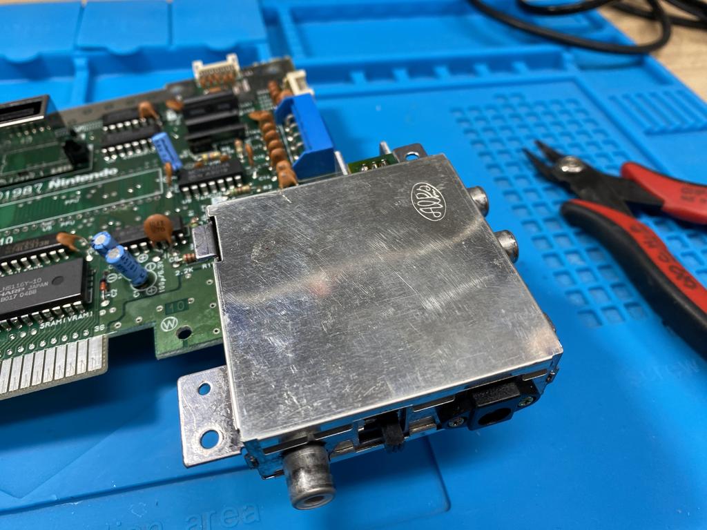
With that done, I grabbed hold of the power module with one hand, while holding the main board with the other, and rocked the power module back and forth until it came free:
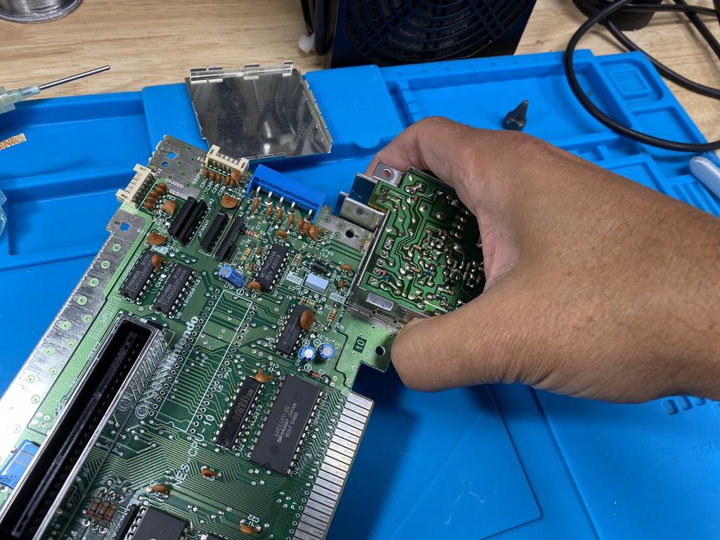
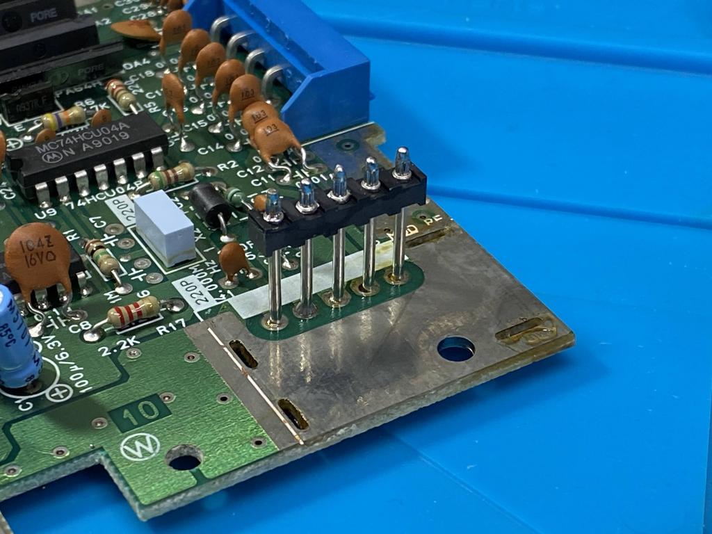
We’re left with the 5 pins still attached to the main board, ready to be soldered to the new power module later:
Push main board capacitors flat #
As with the NESRGB, the caps on the main board need to be pushed down flat for the Lava RGB PCB to fit:
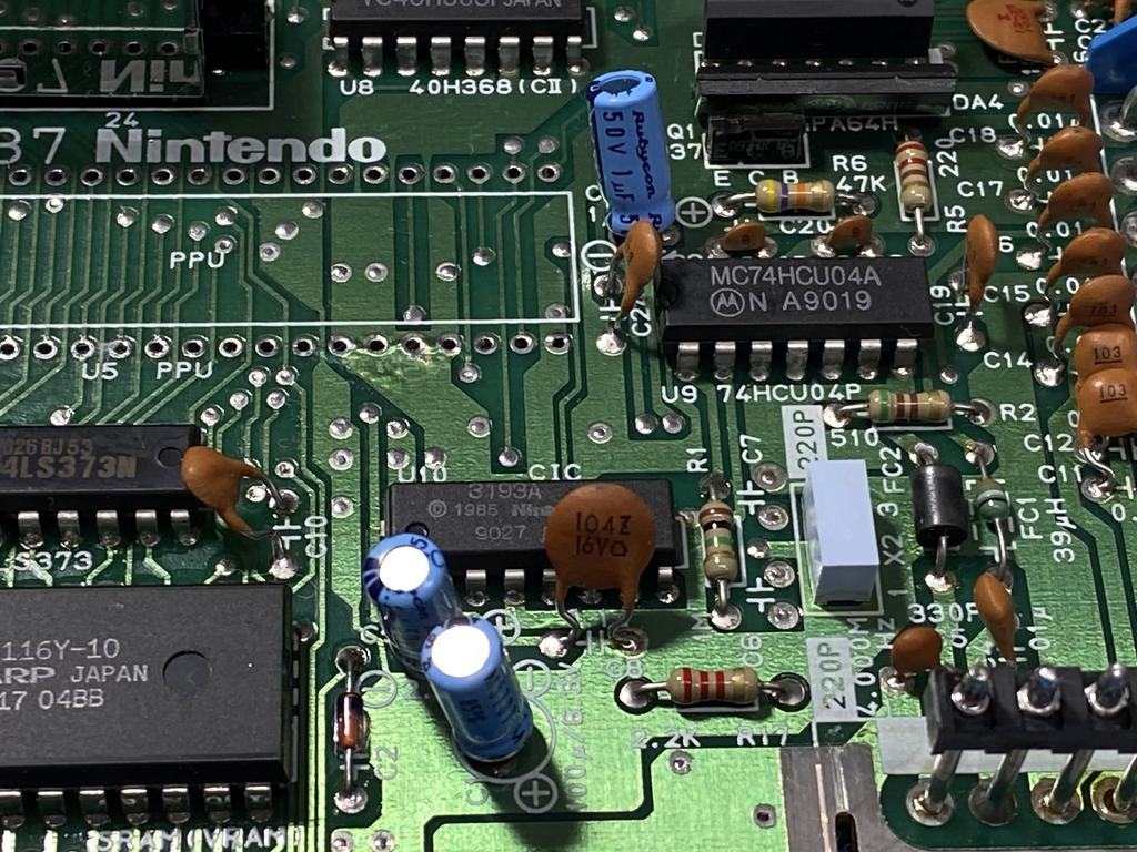
Normally this is simply a matter of pushing the caps down while heating the vias with a soldering iron. However, as I have a bunch of NES cap kits that I ordered from Console5, I decided to replace them:
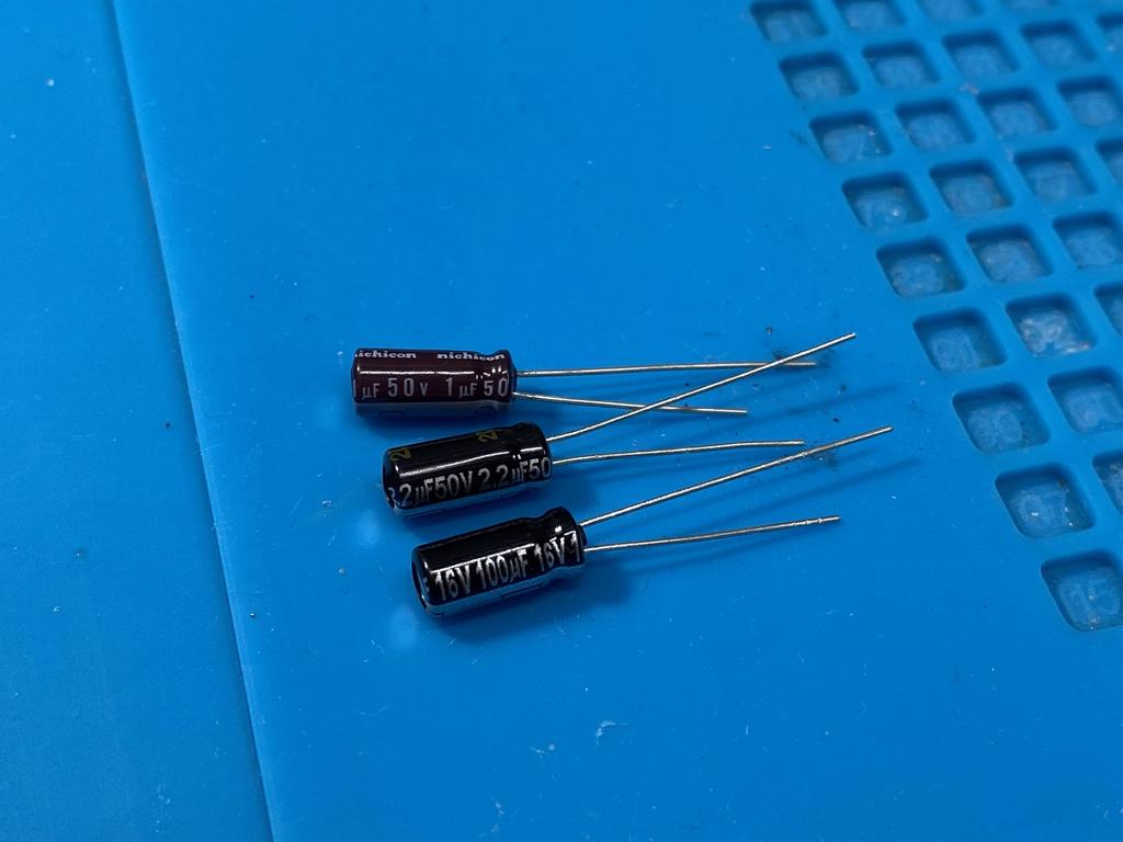
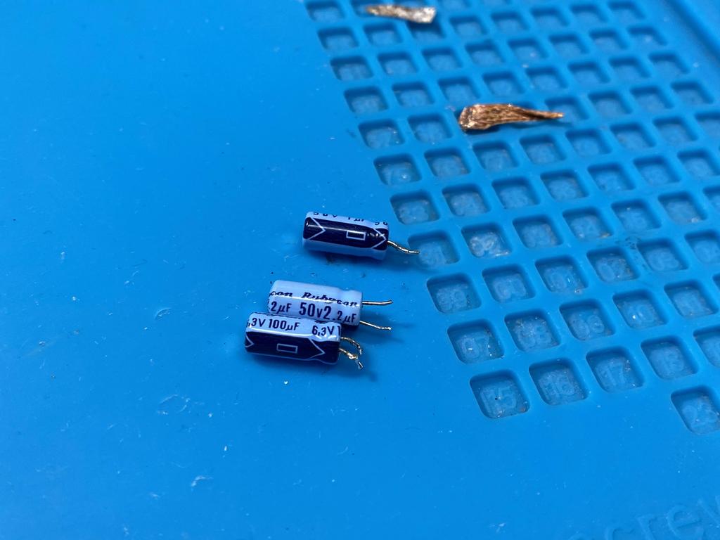
I desoldered the three caps:
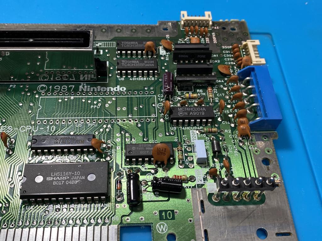
And replaced them with the new ones, making sure to match the capacitance values, and ensuring the voltage rating is equal or above the original one. When placing the caps, I laid them flat before soldering them in:
Solder wires #
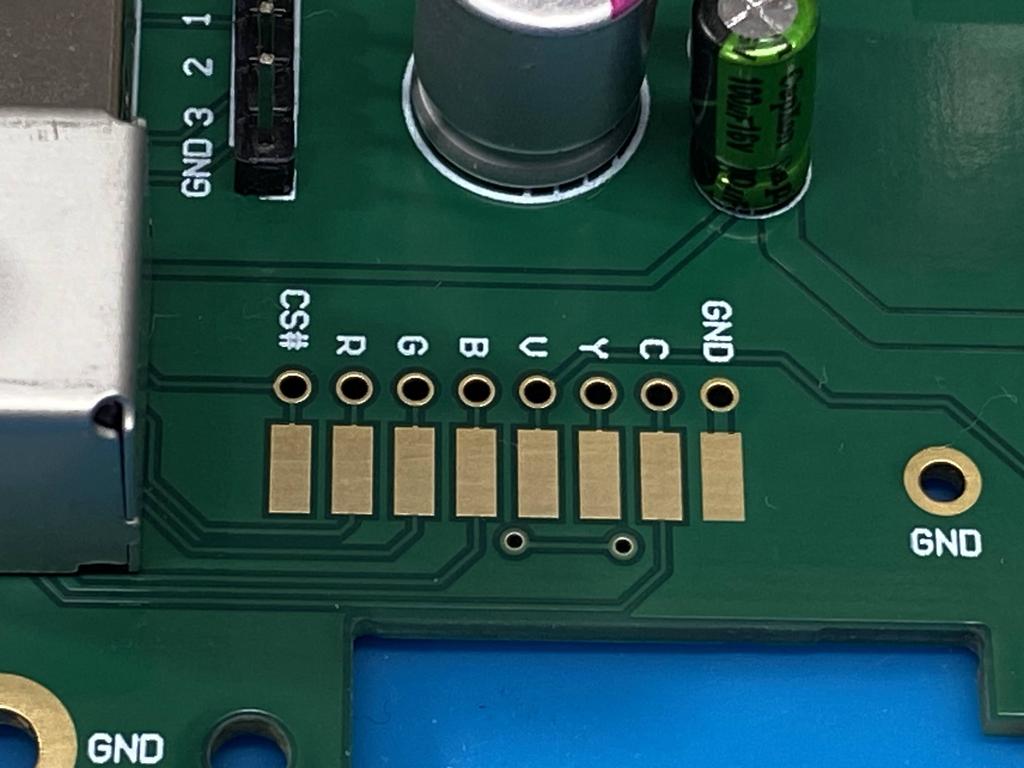
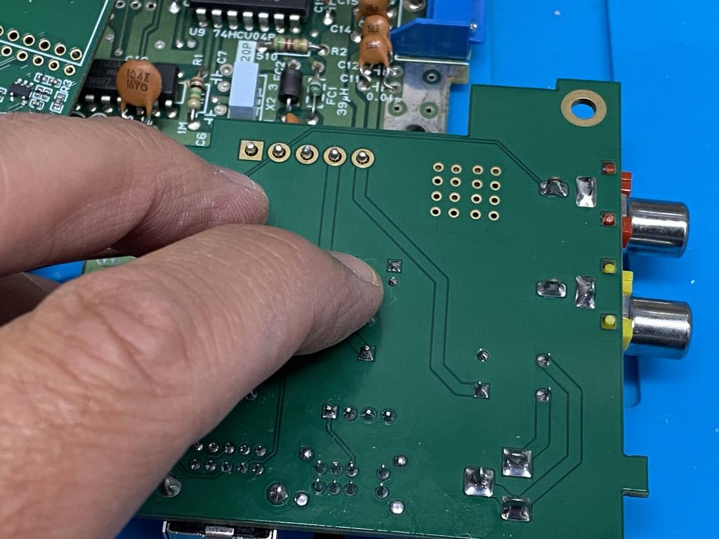
At this point, I decided to solder the ends of the Lava RGB wire connector to the power module and to the main board:
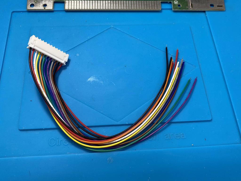
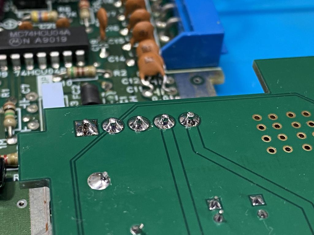
What’s nice is that the order of the pads on the power module and on the mod board match, so it’s easy to solder the first eight wires:
I soldered the eight wires to the pads:
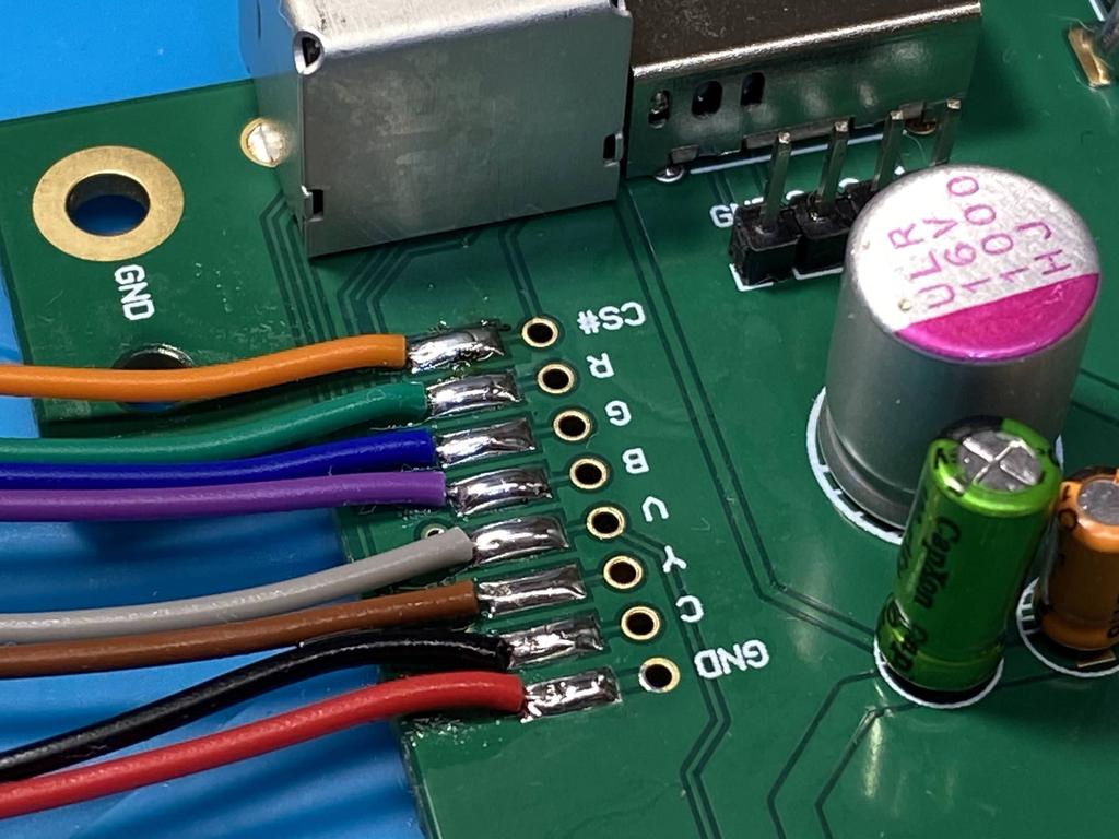
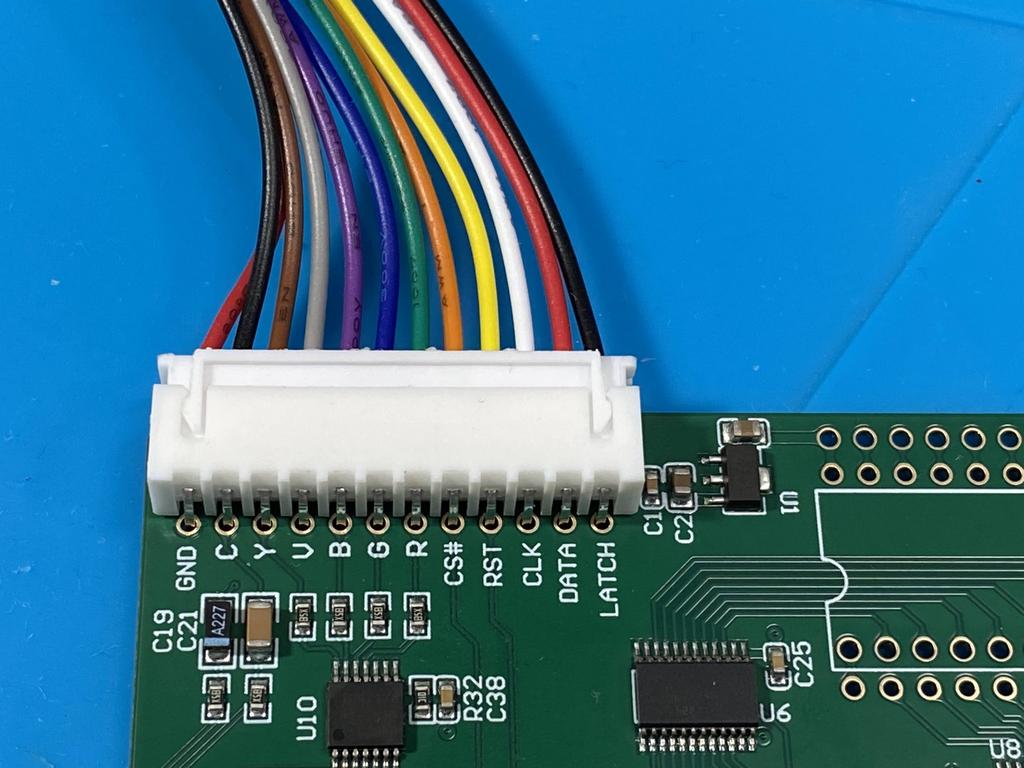
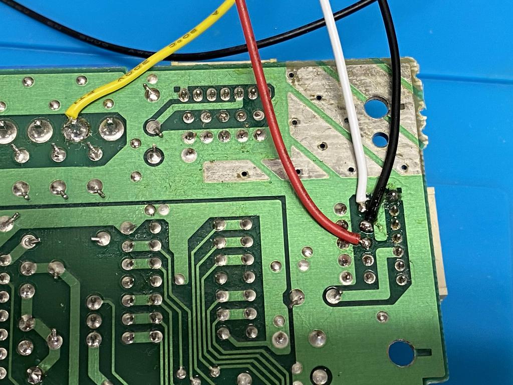
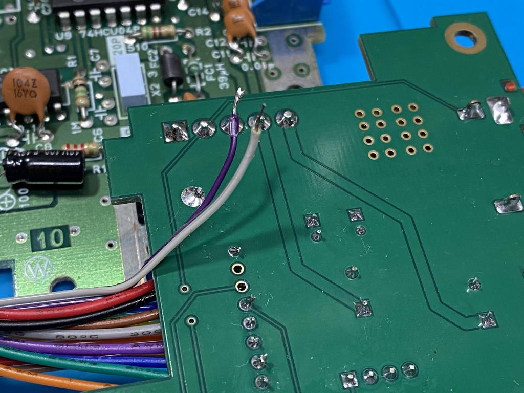
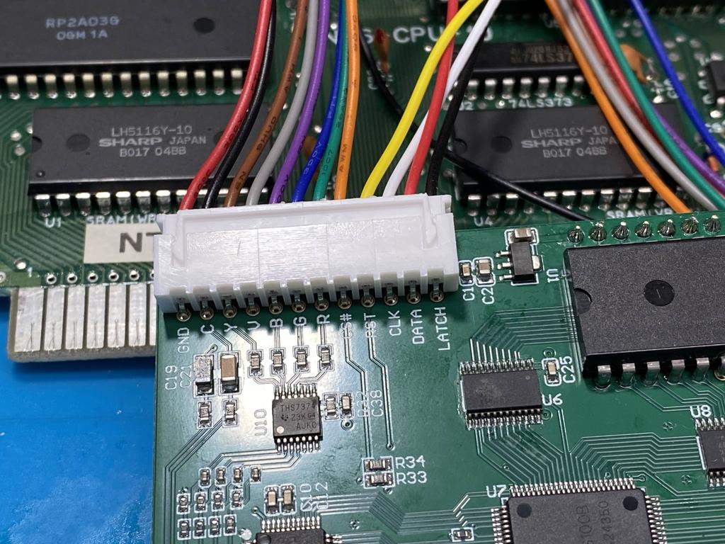
The remaining four wires are used to allow controller 1 to perform an in-game reset (IGR) as well as palette swapping using key combos. IGR is performed by holding Select for about 2 seconds, then pressing A; while for palette swapping, you hold Select for 2 seconds and press Up on the dpad. To make this work, the RST wire needs to be wired to the reset line on the main board (where the actual Reset button is wired to), while the CLK, DATA, and LATCH pins need to be wired to their respective pins on the player 1 controller input lines.
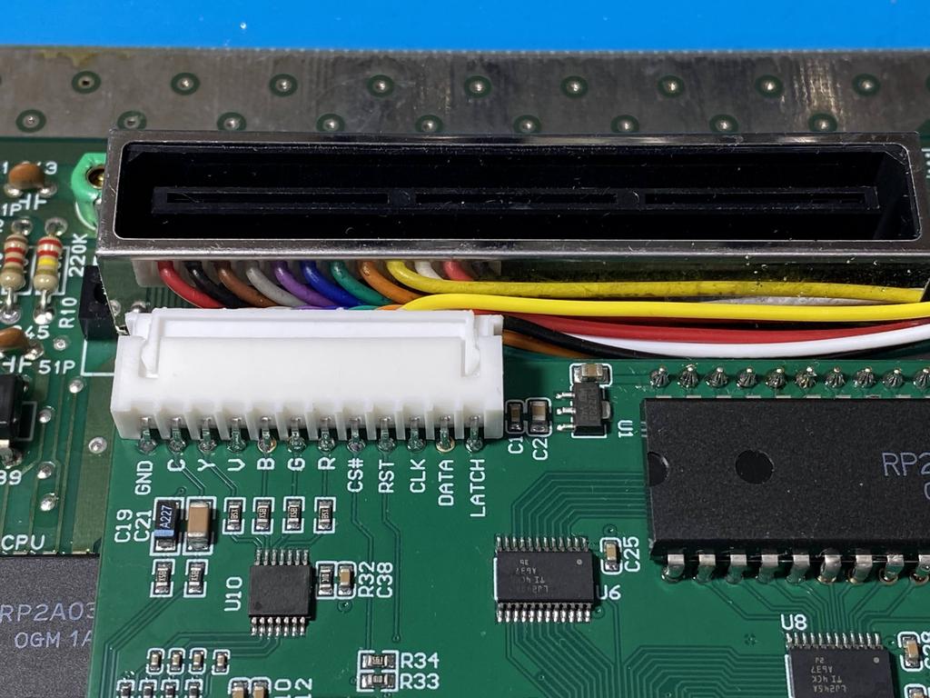
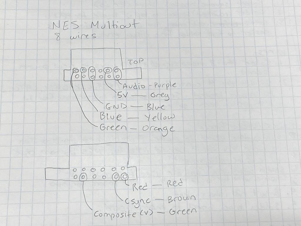
I put this handy image together to identify the pins to solder to:
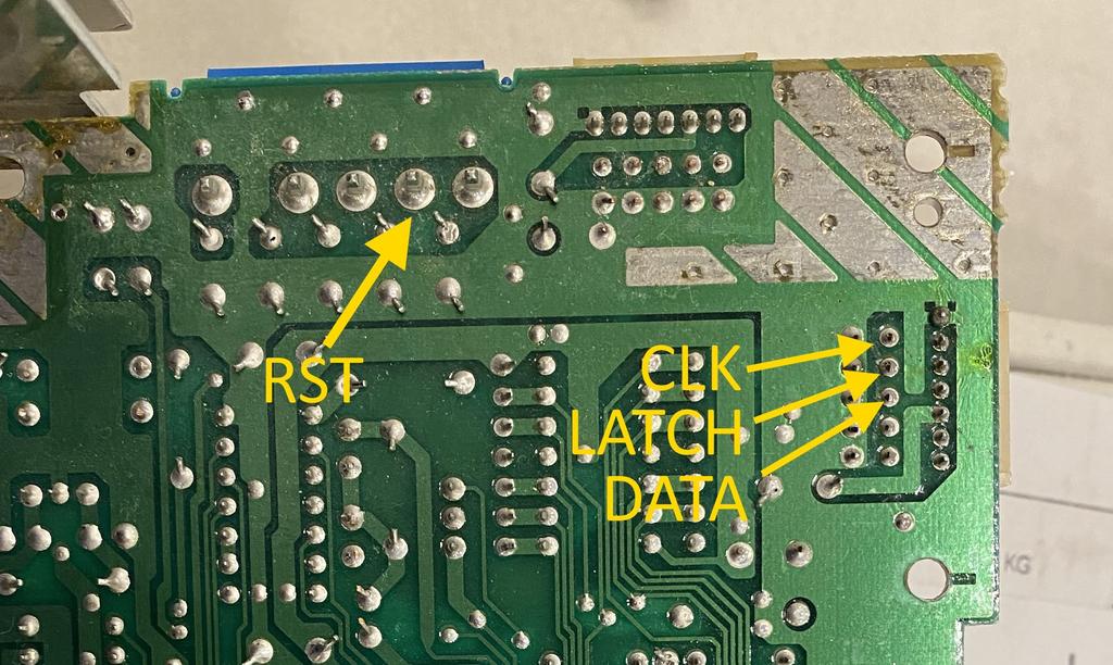
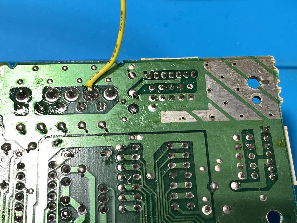
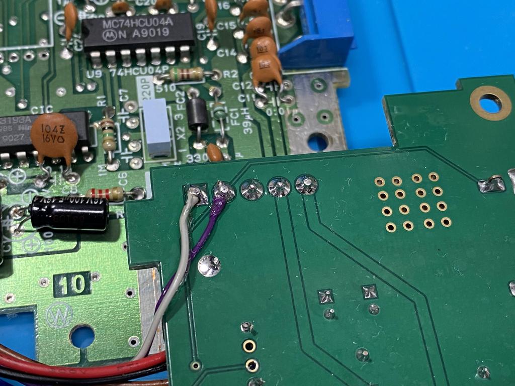
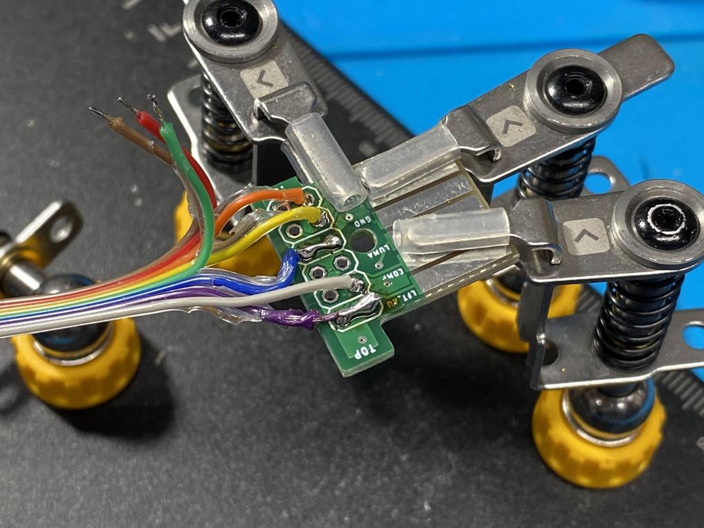
Noting the colors of each pin, I first soldered the RST line:
Then I soldered CLK, DATA, and LATCH. Note that DATA and LATCH are not in the same order as on the Lava RGB PCB:
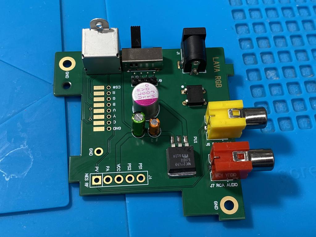
Power module #
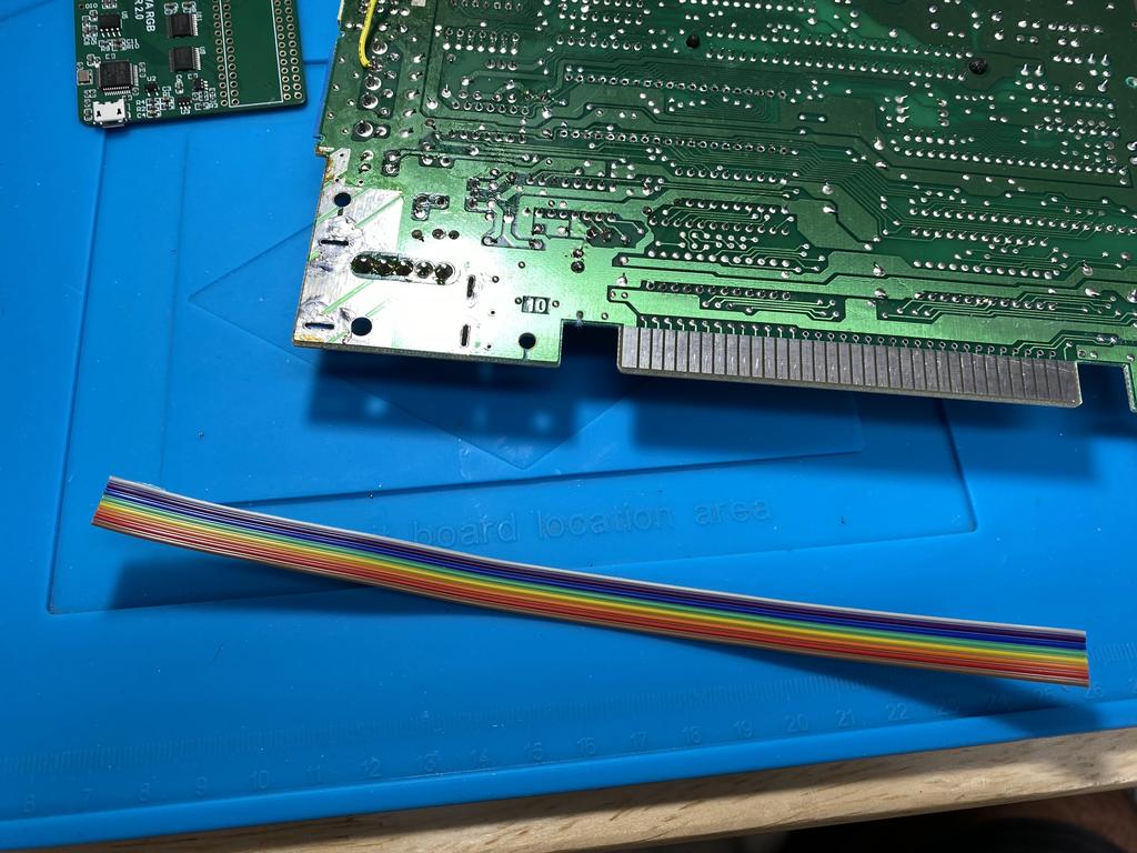
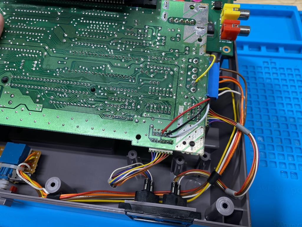
As already mentioned, for my install I planned to add a SNES-style multiout. Rather than grab these connections from the Lava RGB mod board itself, I decided to get them from the power module since it’s closer to where the port would be installed. For this, I used an 8 wire ribbon cable:
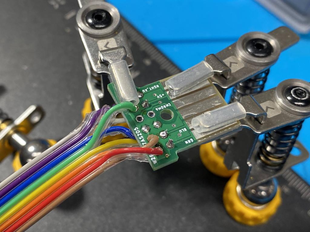
In retrospect, I should have made this cable longer, as I was limited to where I could place the multiout. Anyway, I soldered the cable to the power module. Conveniently, the power module PCB offers two ways to connect wires to it, pads and vias, so I used the vias for this:
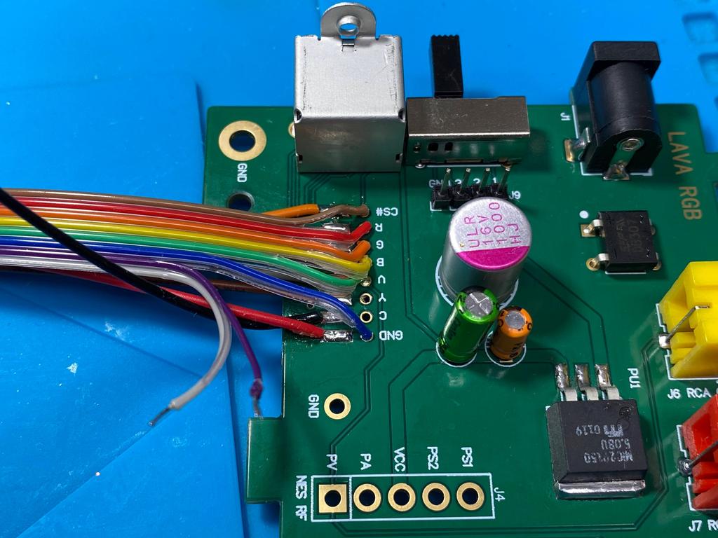
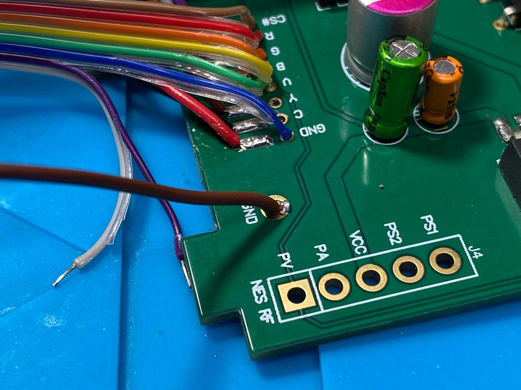
Note that two of the wires, the grey and the purple, are not soldered yet. One of these will be used for 5V, and the other for audio, both of which will be wired later to the PV and PA pins of the 5 pin connector.
I also soldered a wire to GND, and soldered it to the ground plane of the main board:
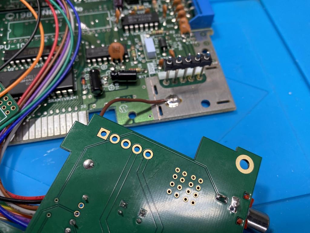
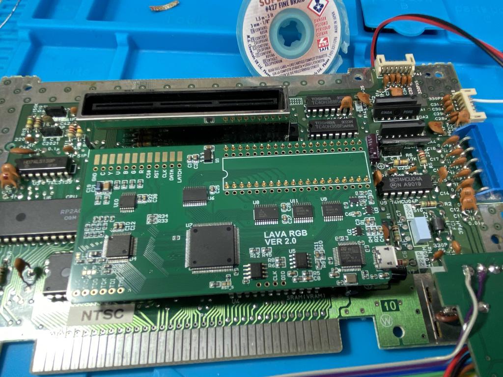
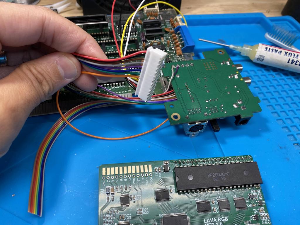
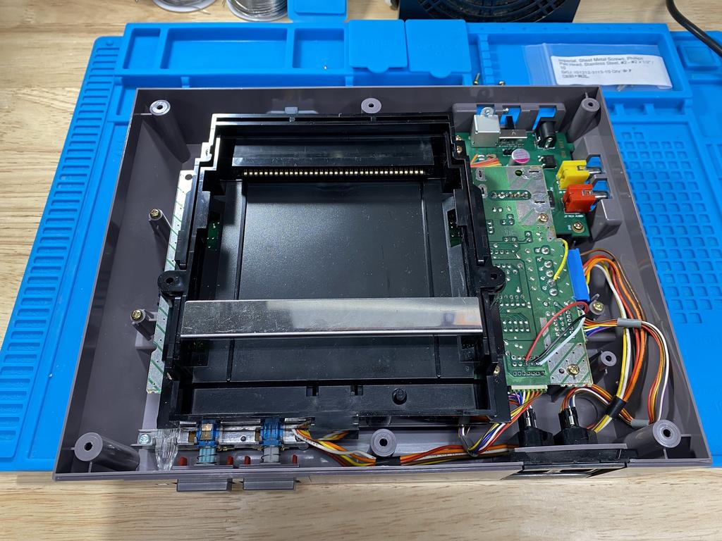
At this point, I loosely positioned the PCBs to get a sense for where I was heading:
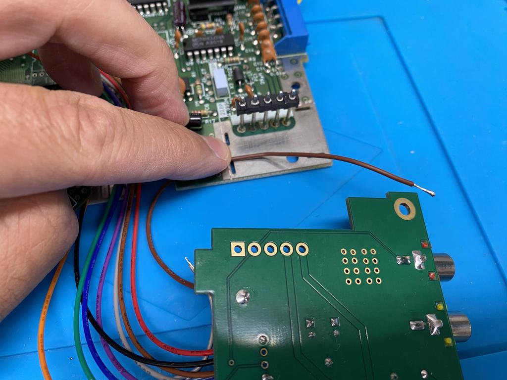
Next, I soldered the power module to the five pins coming from the main board:
And now I could solder the 5V and audio wires to PV and PA respectively:
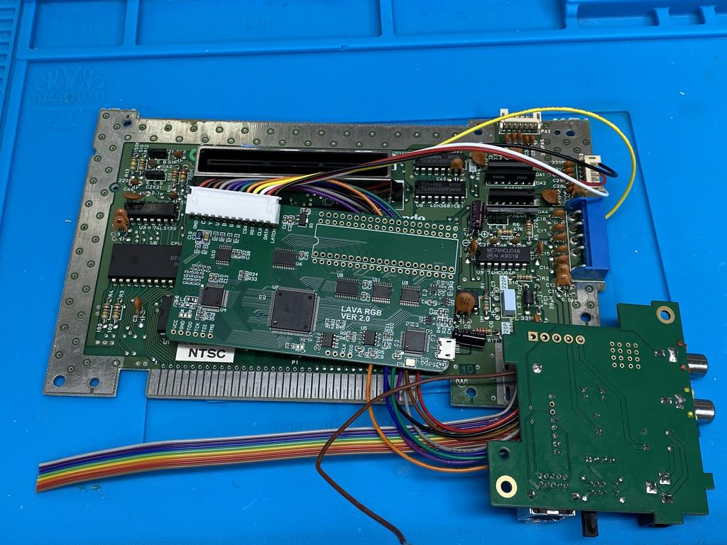
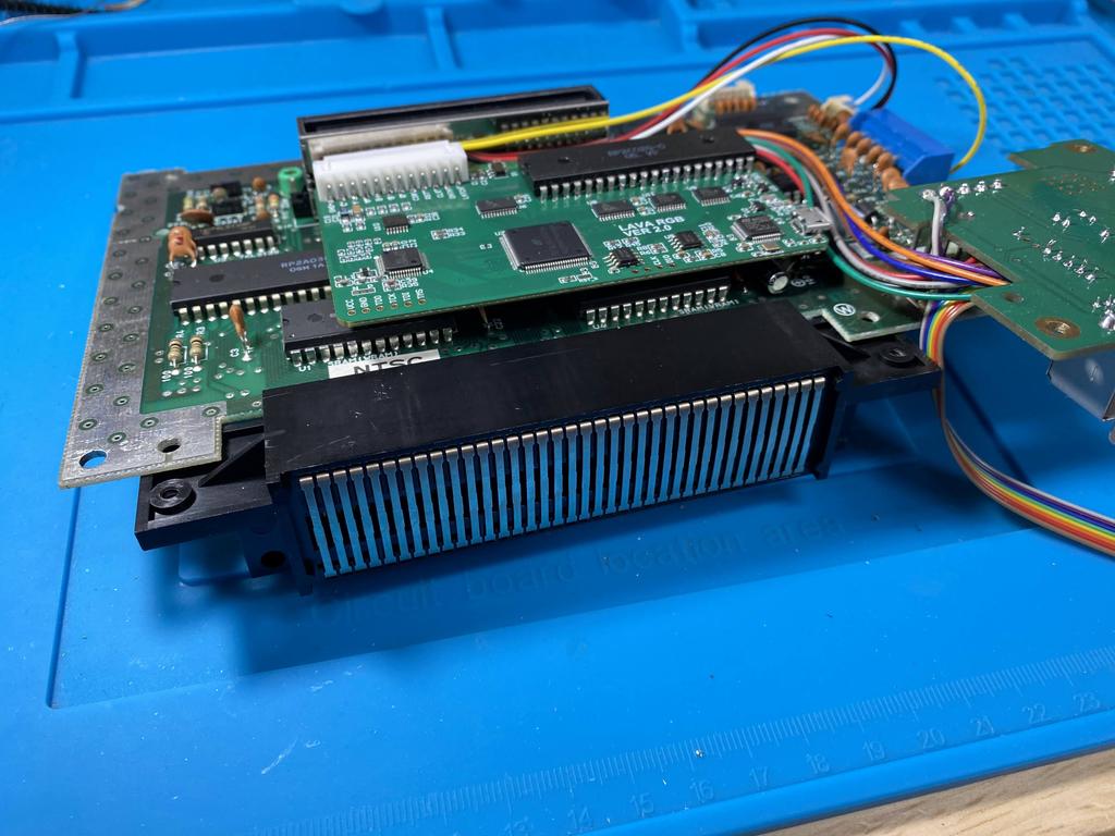
This is what everything looked like at this point:
Mod board #
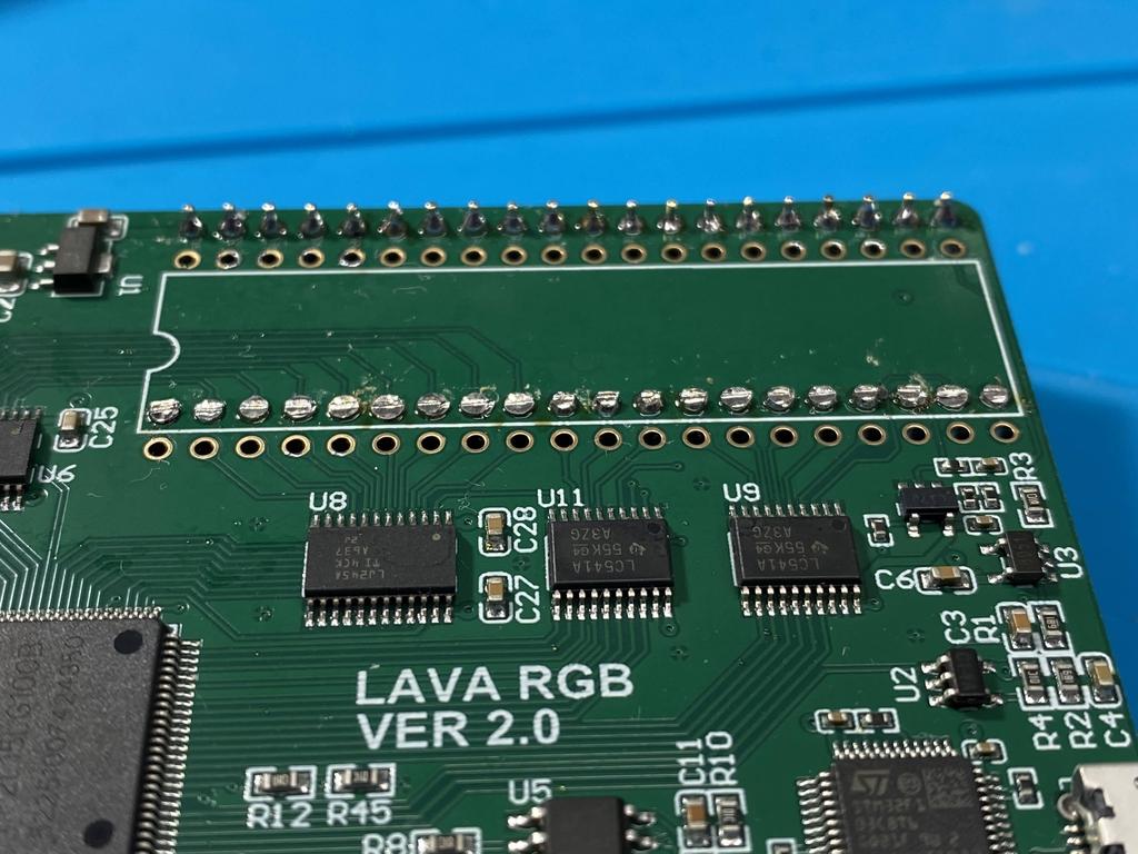
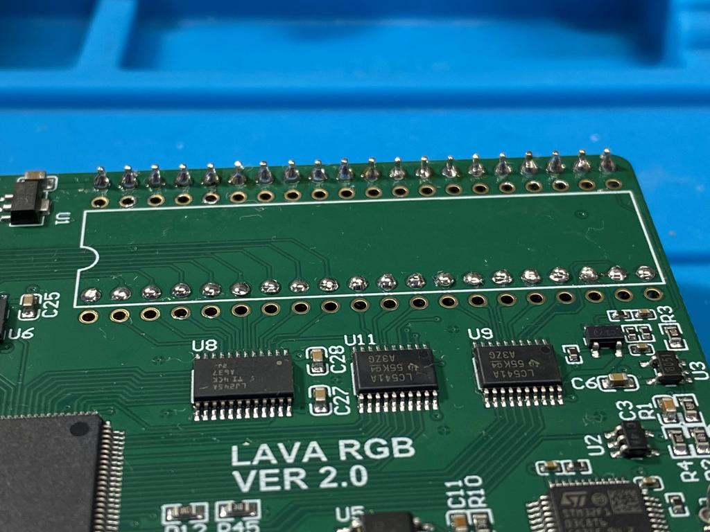
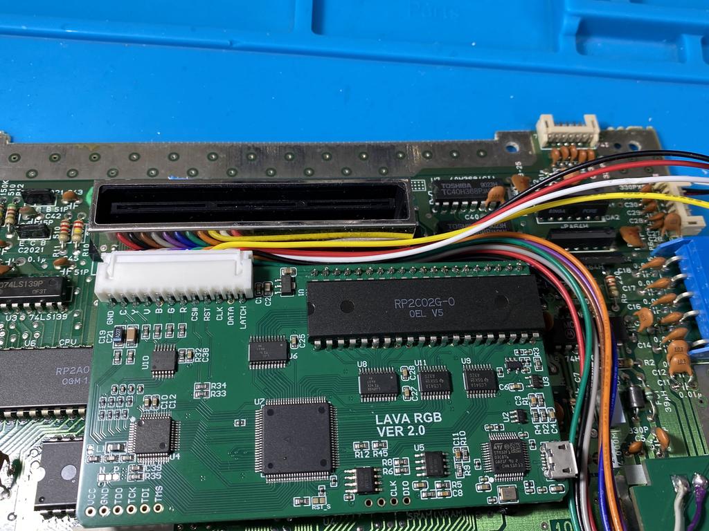
Next up was installing the mod board:
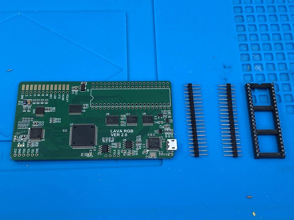
As can be seen above, the kit includes two 20 square pin headers. Their official instructions expect you to solder the mod board PCB directly to the NES main board using these square pin headers, making sure to first solder the round pin socket onto the mod board itself so that the PPU can be inserted into it. The apparent advantage here is being able to swap out the PPU, but with the major disadvantage that the mod board cannot be removed from the main board, making it difficult to service the mod in the future. So instead of this, I did as is usually done with the NESRGB mod: solder the socket to the main board, and the PPU directly to the mod board. For this, I needed to either get a socket that works with the included square pin headers, or rounded pin headers - I chose the latter.
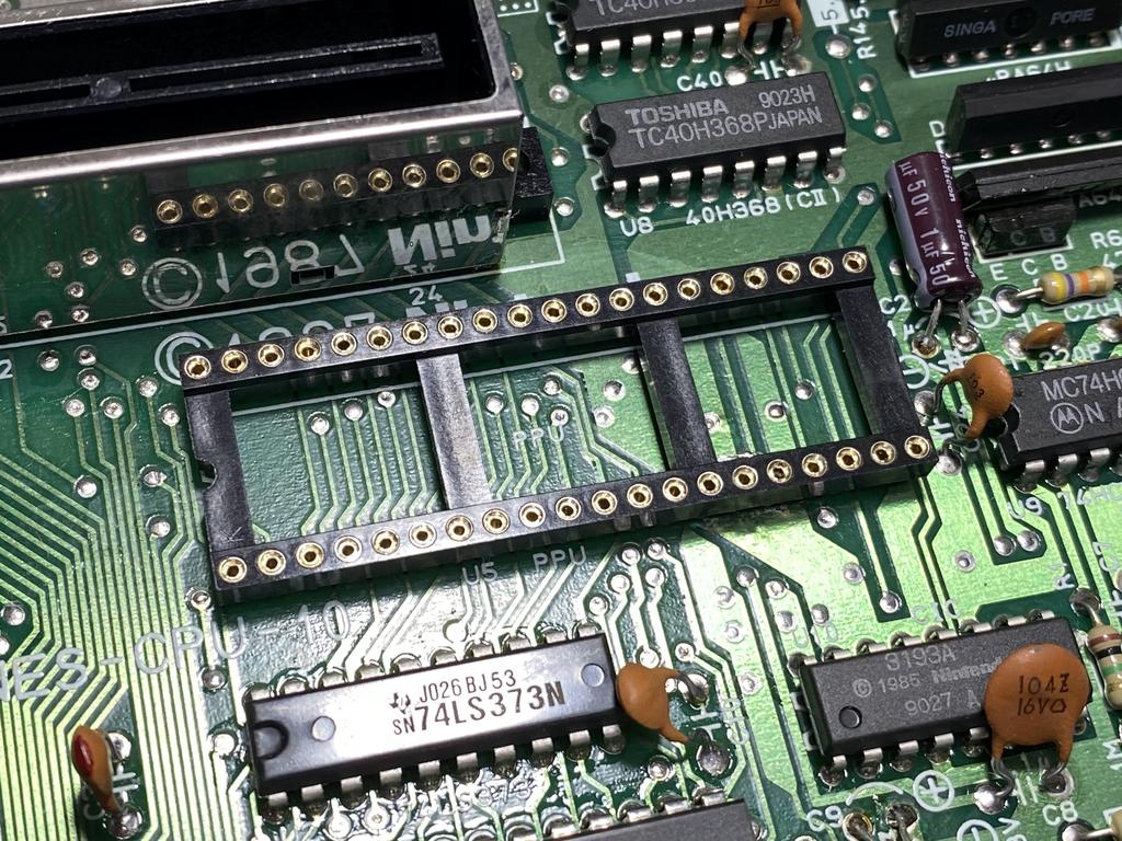
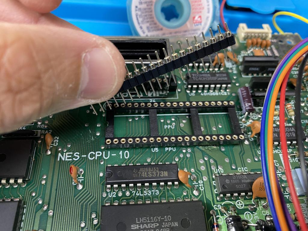
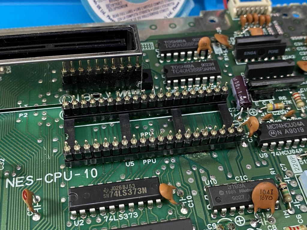
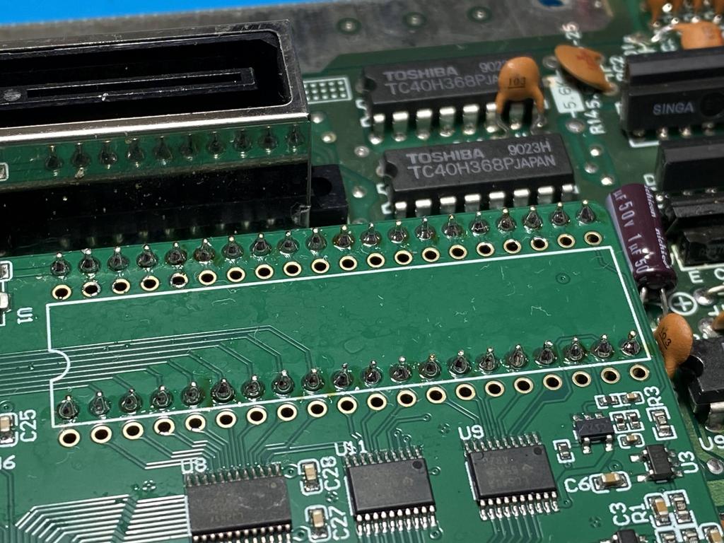
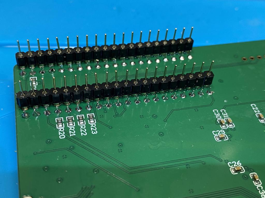
I soldered the socket to the main board, making sure to line up the notch:
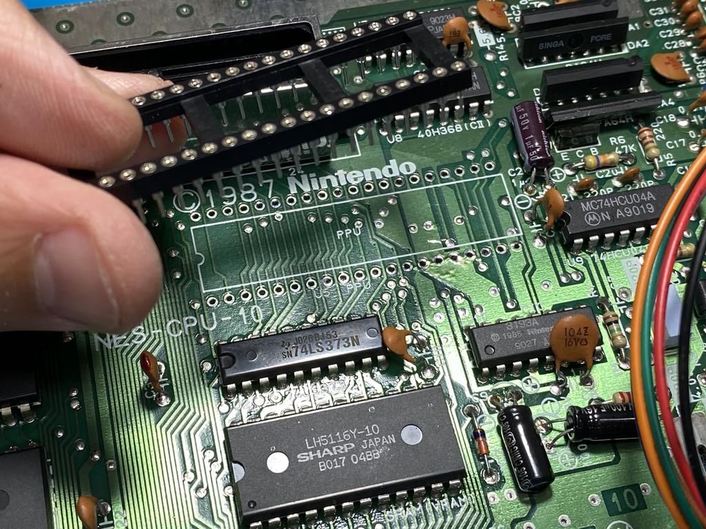
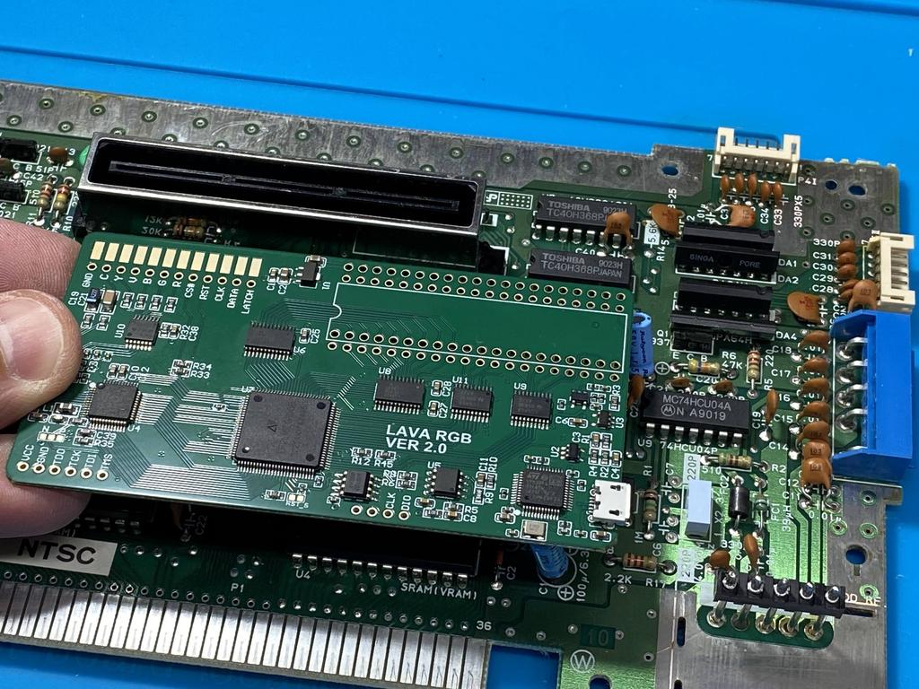
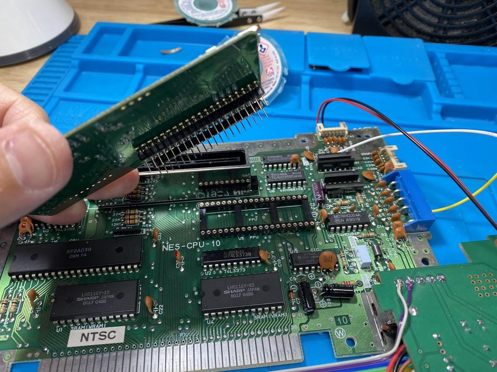
I inserted the two rounded pin headers I purchased separately into the sockets, longer pins down:
Then laid the PCB over the pins, making sure to insert them into the right vias, and soldered them in place:
I carefully detached the mod board from the socket by rocking each edge back and forth. Some care has to be taken here as these rounded pins can bend and break very easily:
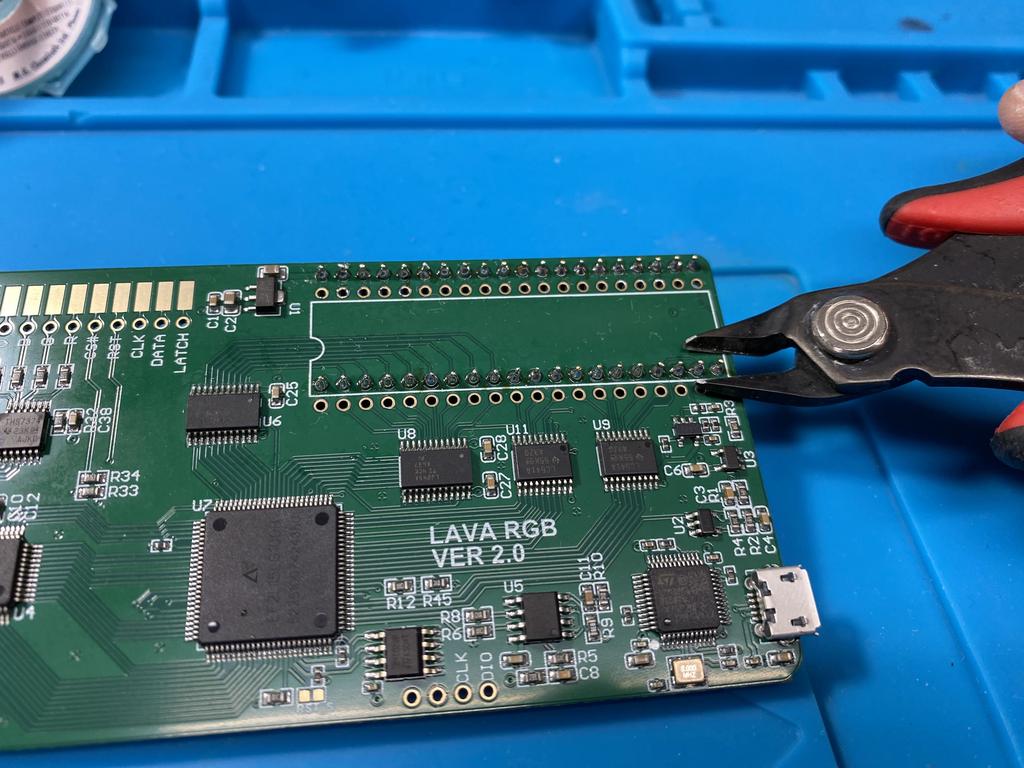
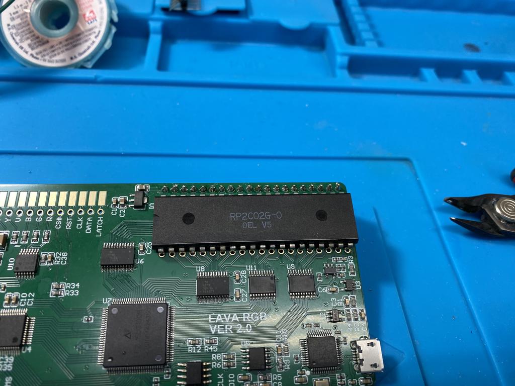
Before soldering the PPU to the mod board, I use my flush cutters to cut down the one set of pins that would be underneath the PPU, and then touched them up with the soldering iron. Although not strictly necessary, this allows the PPU to lay flat on the PCB:
I inserted the PPU onto the mod board, making sure to line up the notch, and soldered it in place:
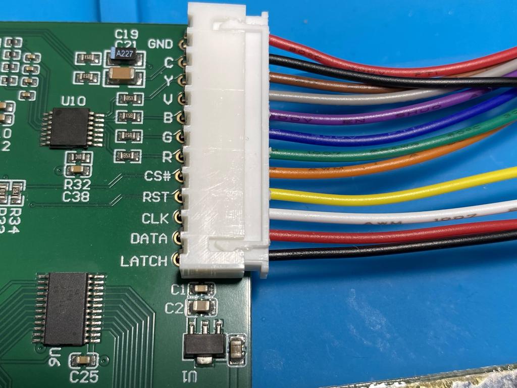
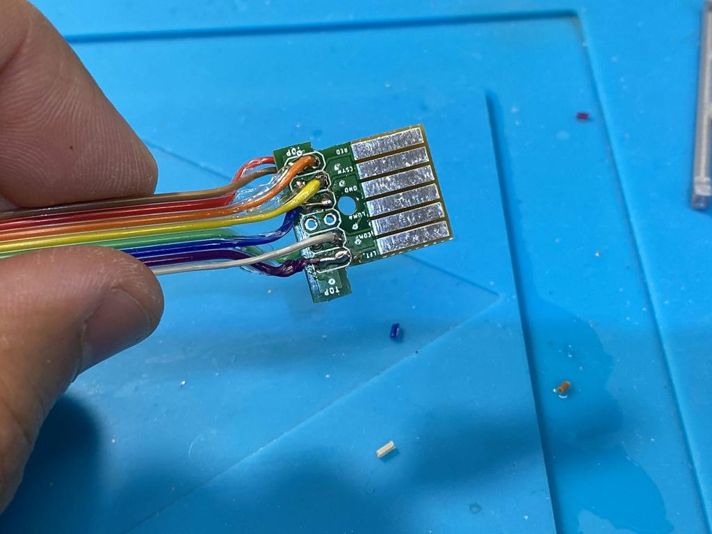
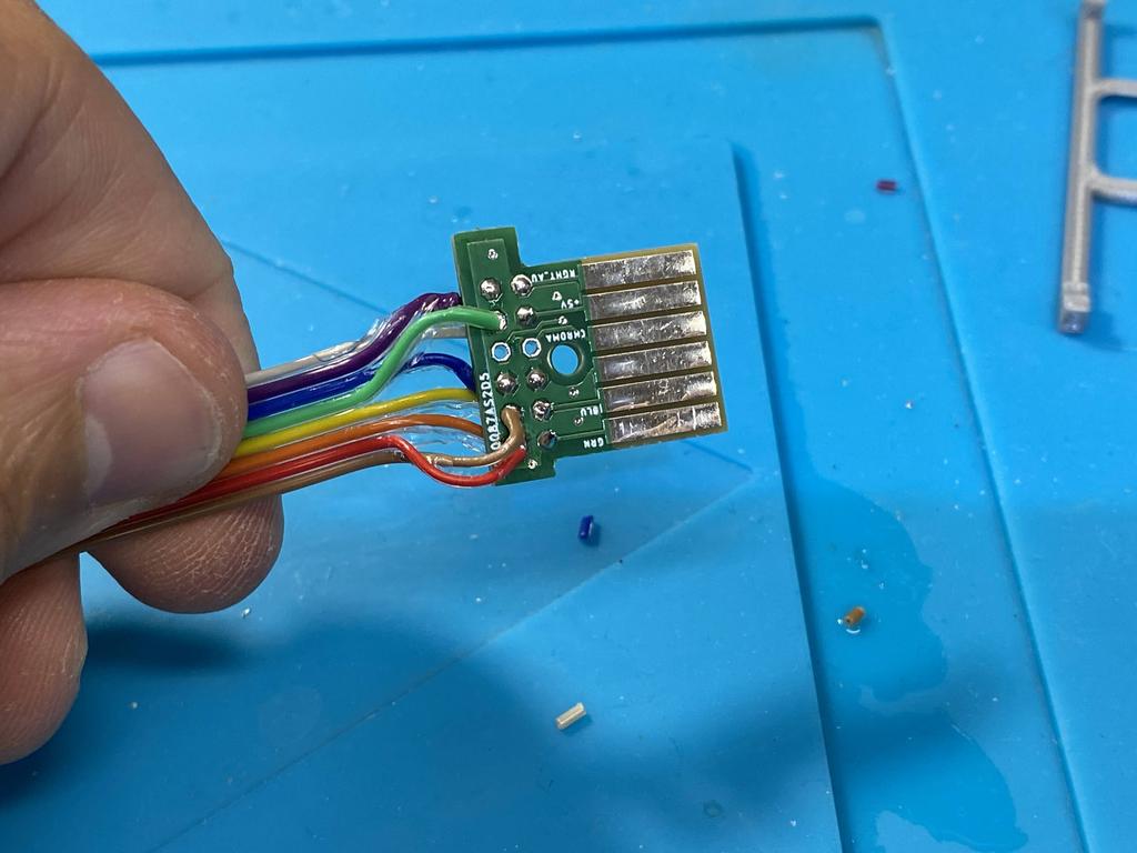
Next, I soldered the wire connector to the mod board:
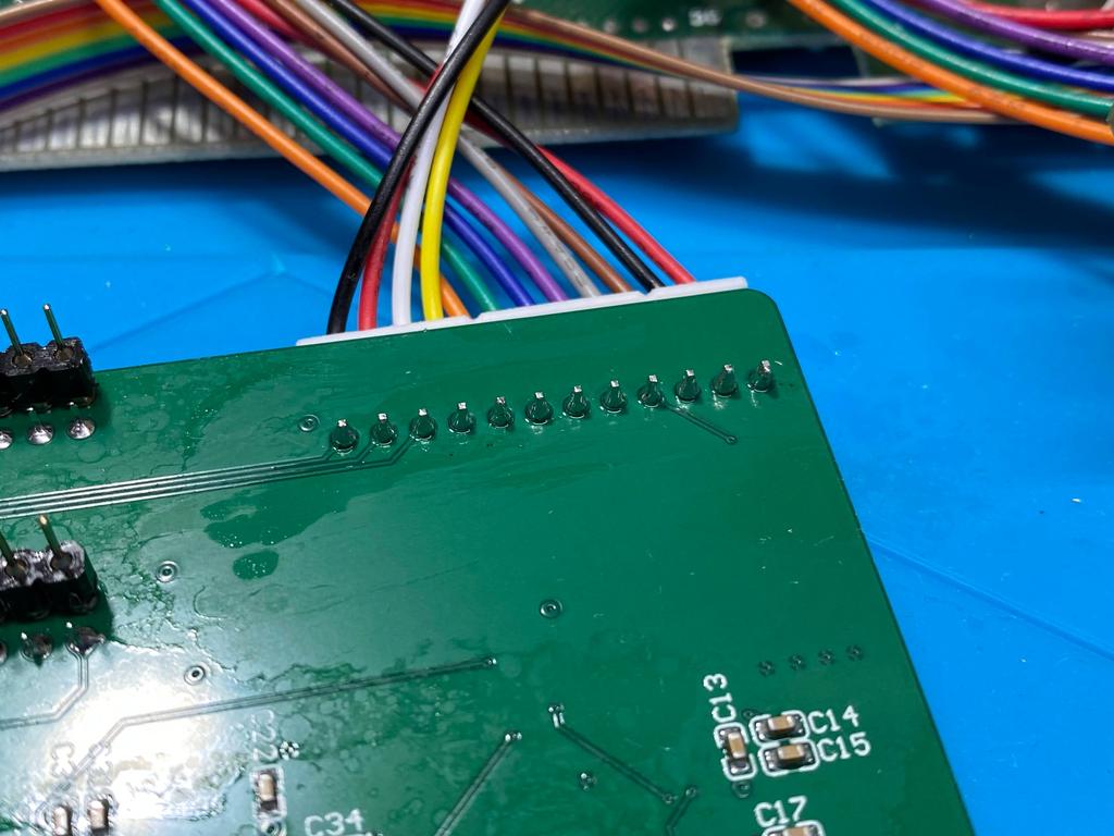
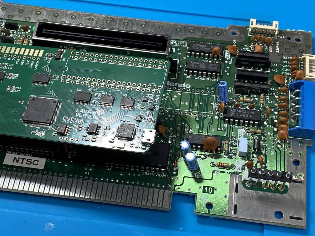
Now I carefully inserted the mod board back into the socket, making sure to line up the socket pins, while also routing the wires down and to the side, as there isn’t much space between the connector and the expansion port (note that we’re seeing the reflection of the wires on the edge of the expansion port):
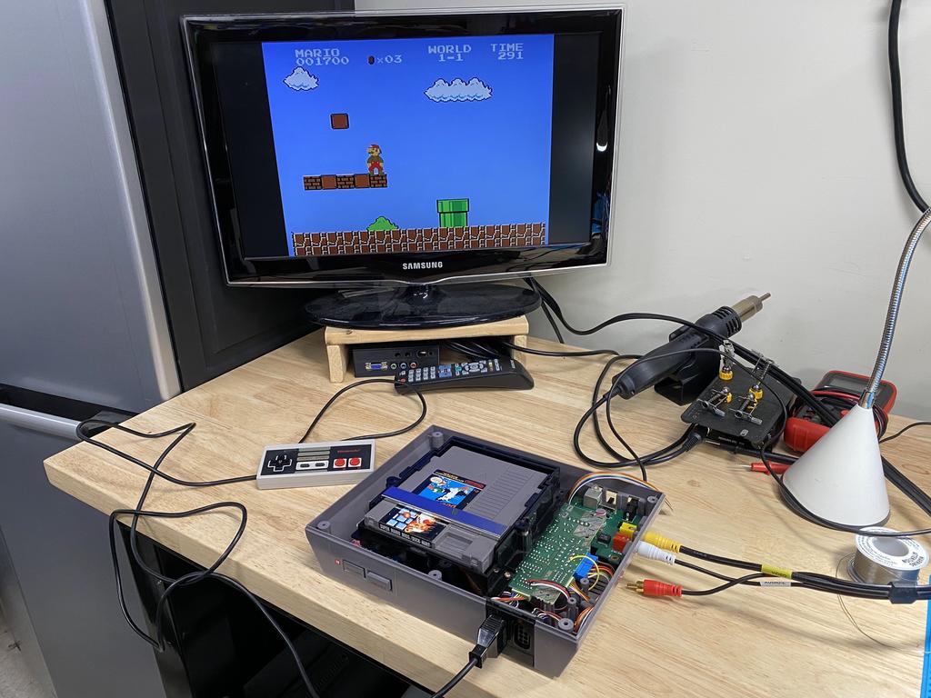
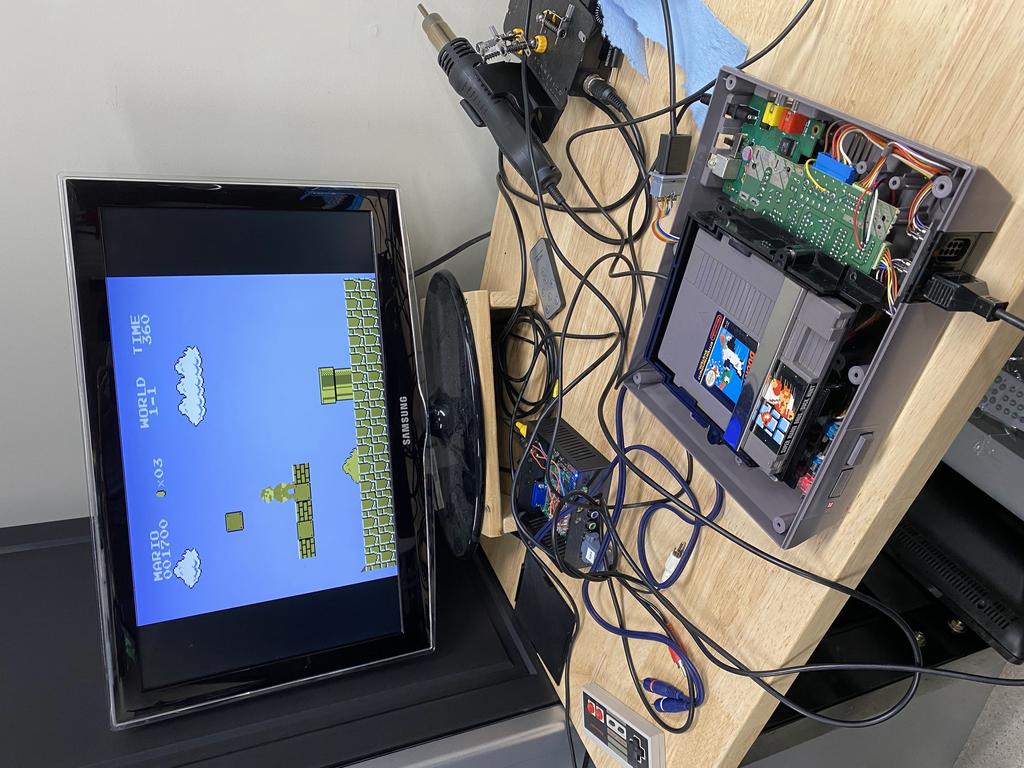
First test #
At this point, I could finally test the mod out. I hadn’t soldered the multiout yet, and I didn’t have a way to hook up the Saturn-style DIN, so I couldn’t test RGB, but I could test composite. So I loosely put everything together and composite video and audio worked perfectly:
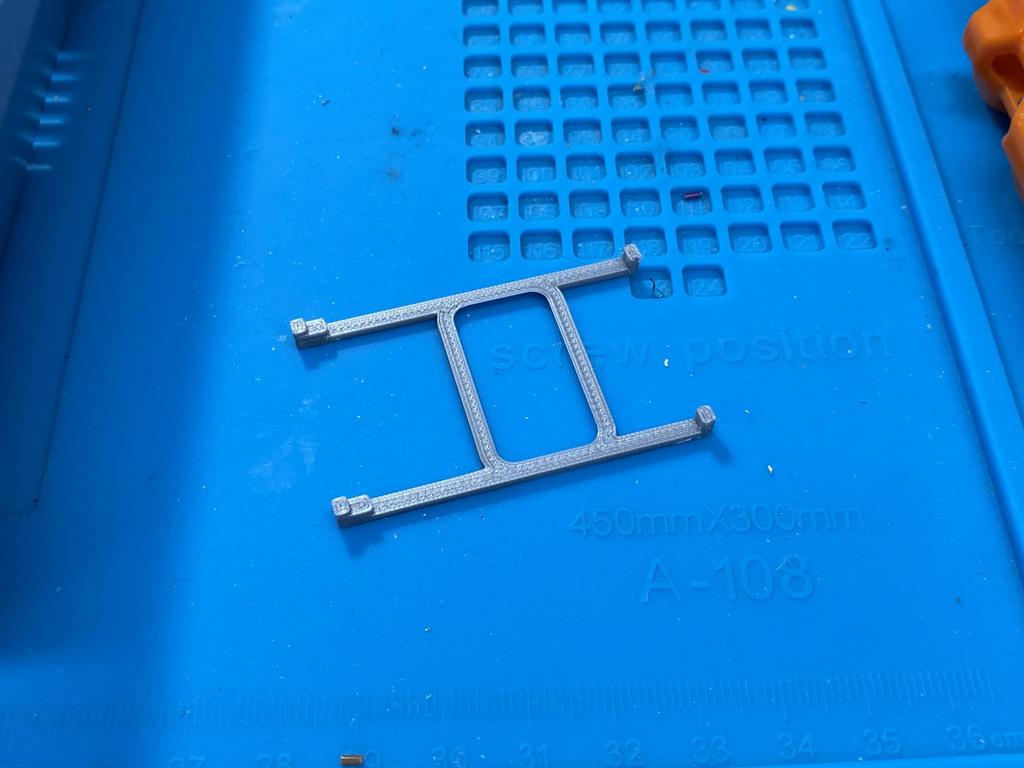
Multiout #
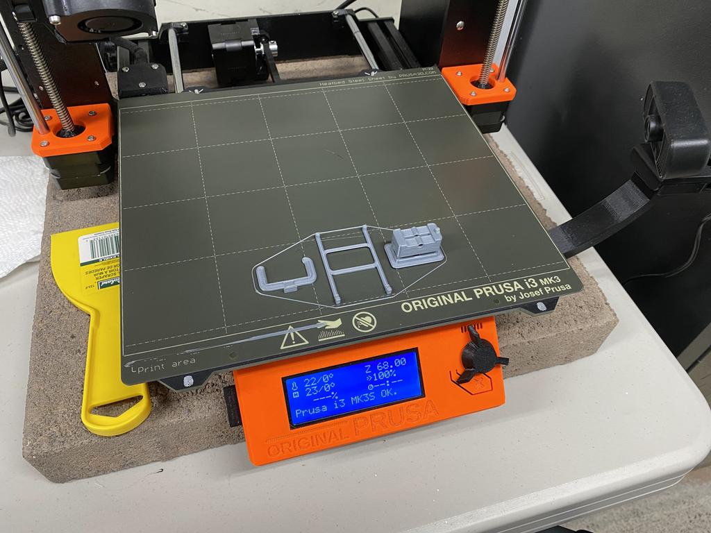
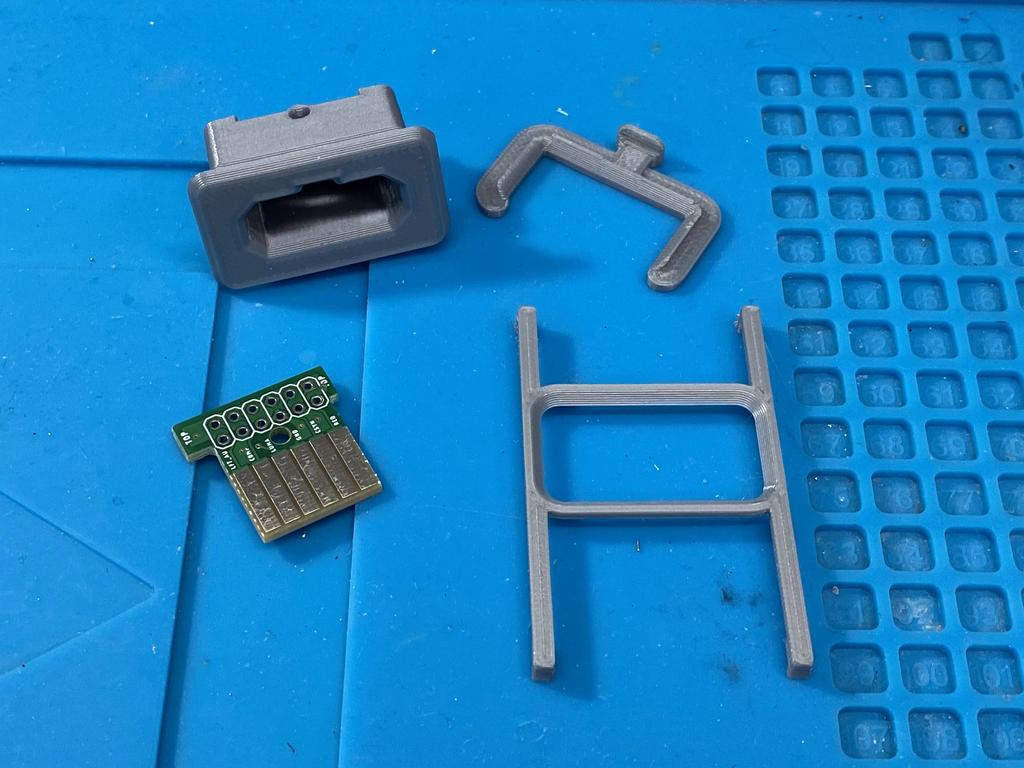
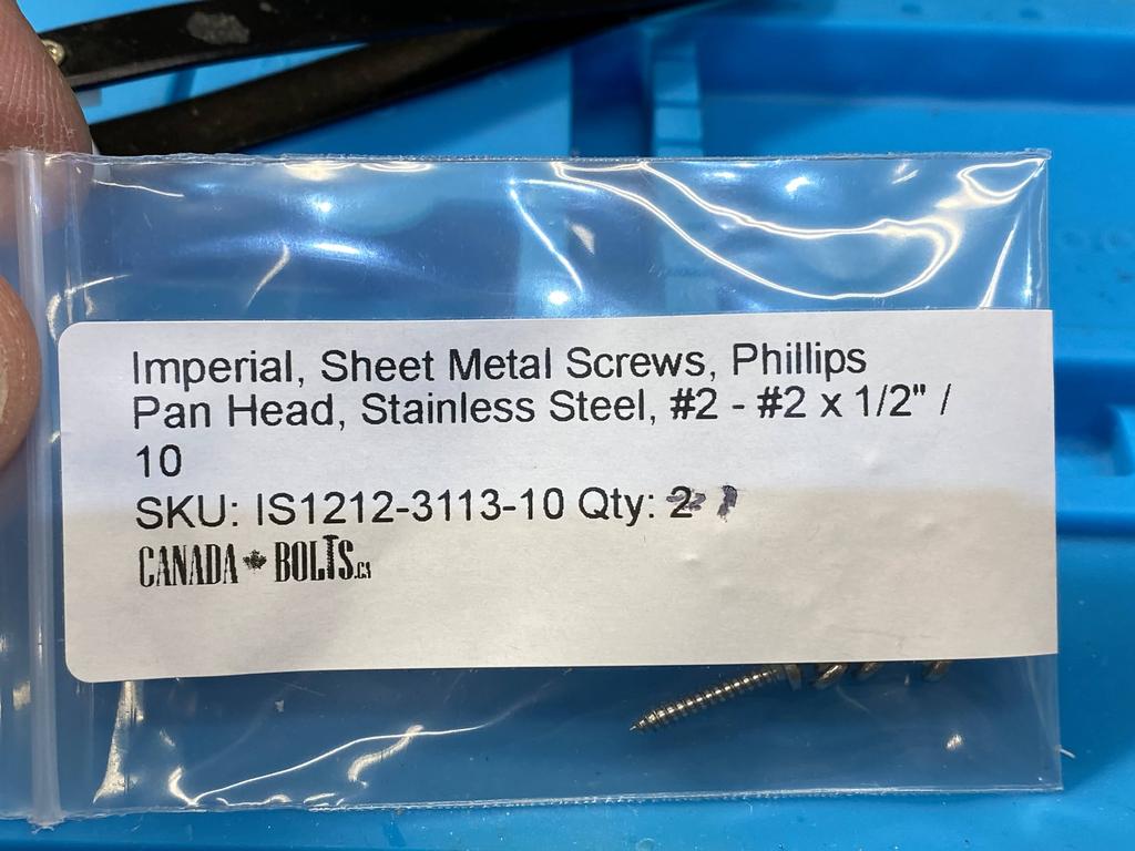
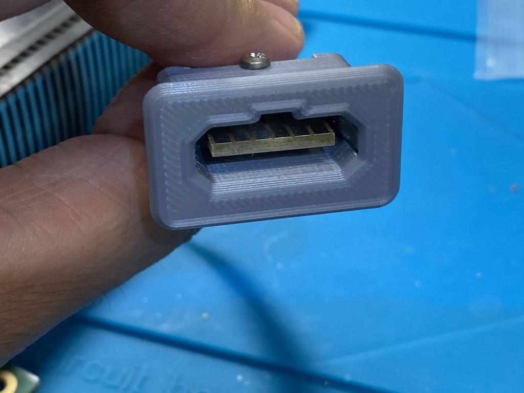
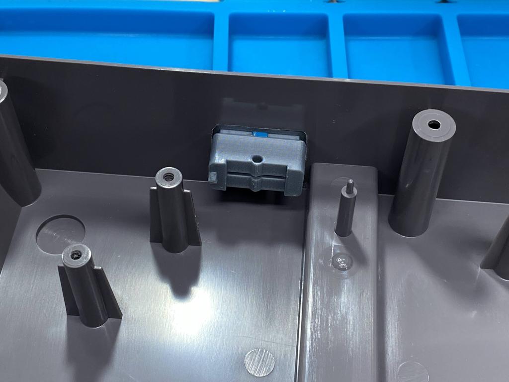
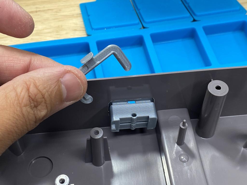
For the SNES multiout, I 3D printed Laser Bear’s Multiout Panel Mount Snap In Connector, and used PCBWay to print The Real Pheonix’s PCB. I also needed to order the right #2 x 1/2” screw. Alternatively, one could order the parts directly from Laser Bear and The Real Phoenix. Anyway, here are the parts:
Solder ribbon to multiout PCB #
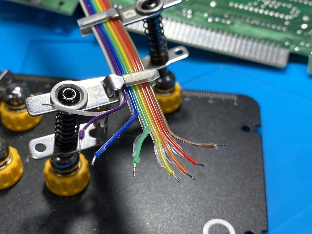
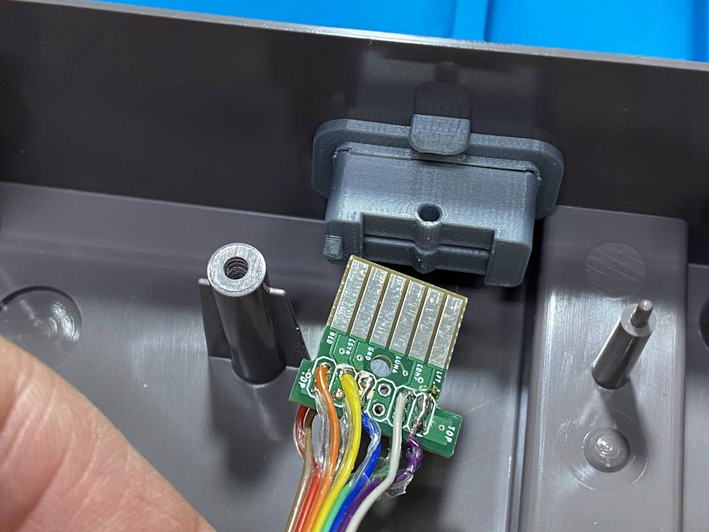
I mapped out the pins I’d need to solder to, along with the specific color wires from my ribbon cable:
I soldered the ribbon cable to the multiout PCB:
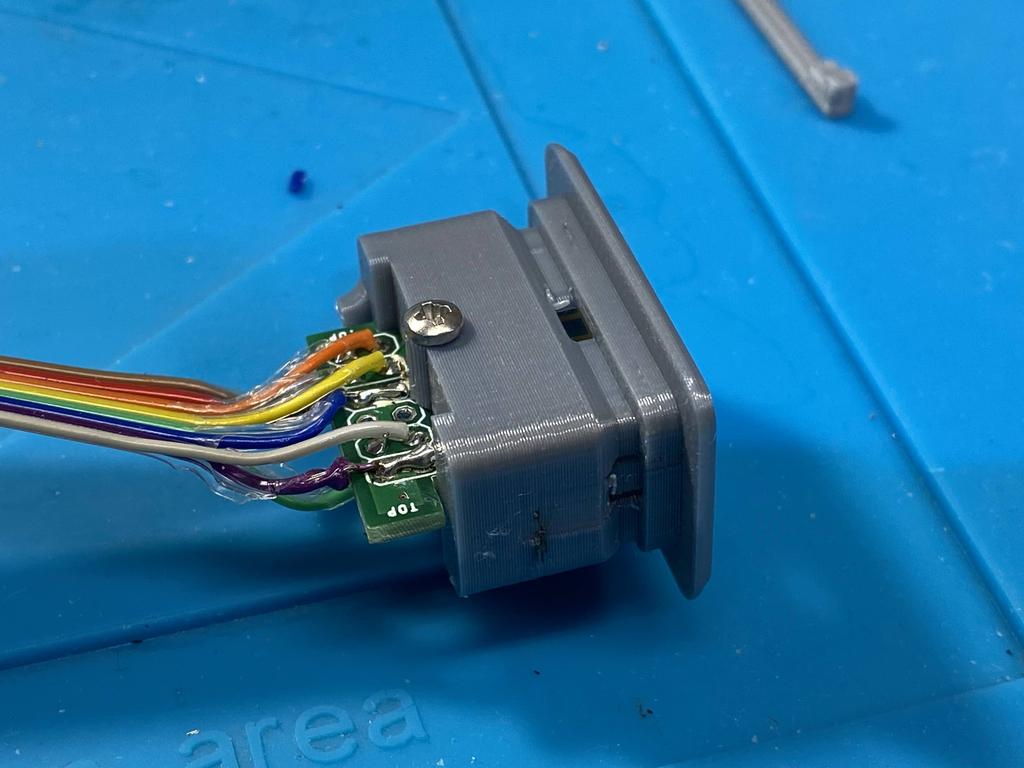
For testing, I inserted the PCB into the 3D printed frame and screwed it in:
Second test #
Using an old cable I made, I gave it a quick test:
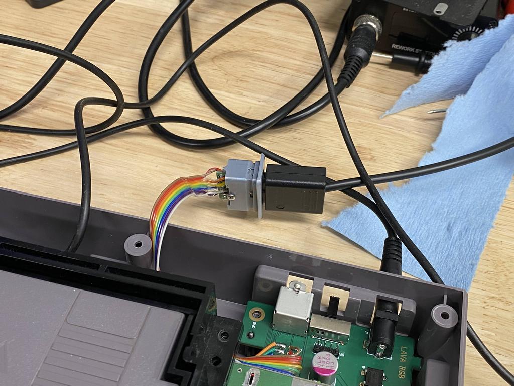
It worked! Although note that the colors aren’t quite right. It turned out that my cable was defective - green wasn’t being passed through. I later used a better cable, and all was fine.
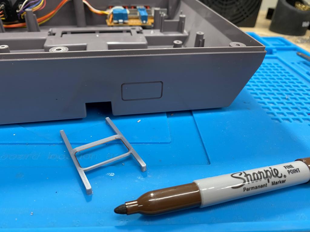
Cut shell for multiout connector #
Using the 3D printed bracket, I marked off where I would need to cut into the shell to fit the 3D printed connector:
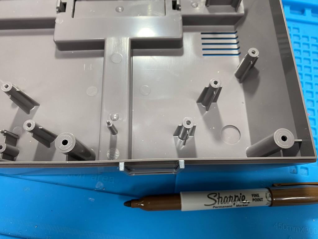
I made sure to position the hole as to not interfere with the posts. I actually wanted to position it more to the right, but as already mentioned, I had cut the ribbon cable too short, and didn’t feel like redoing it.
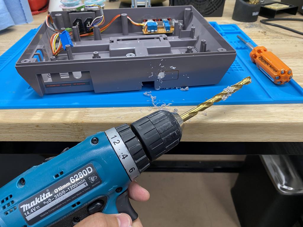
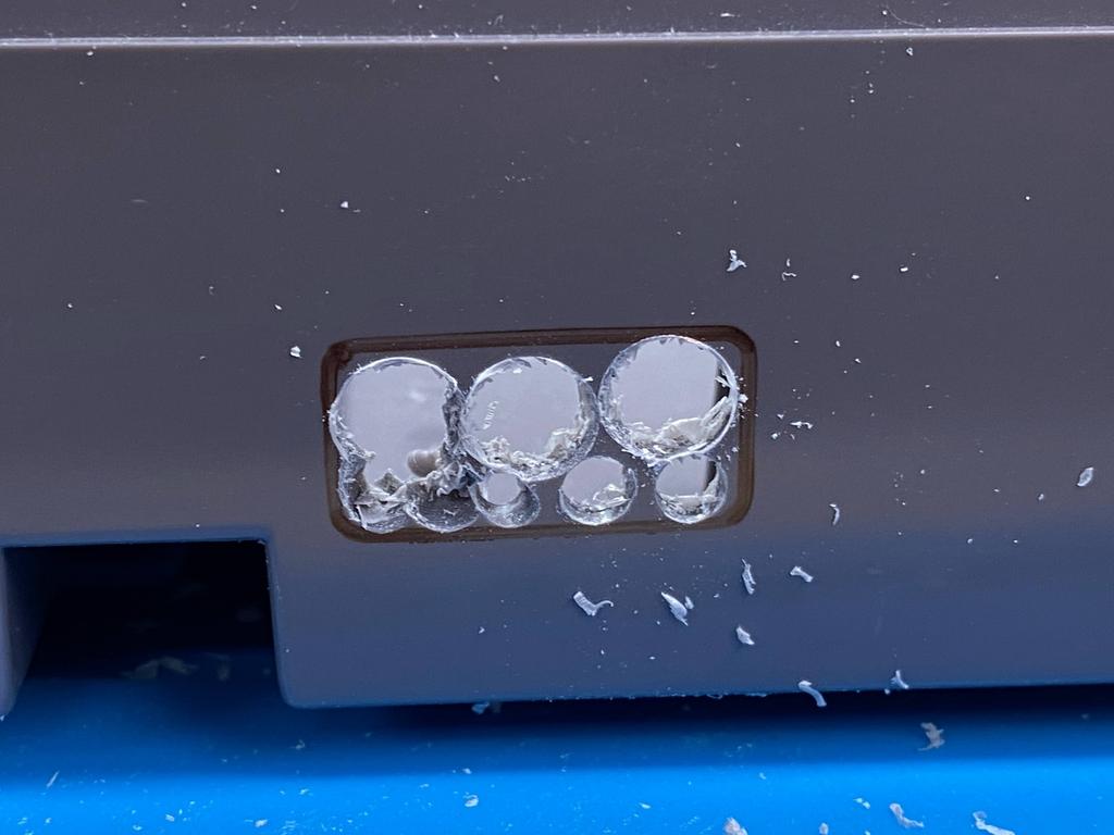
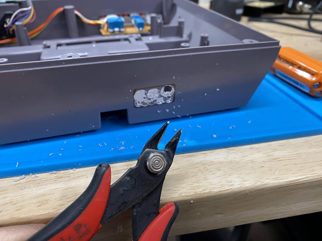
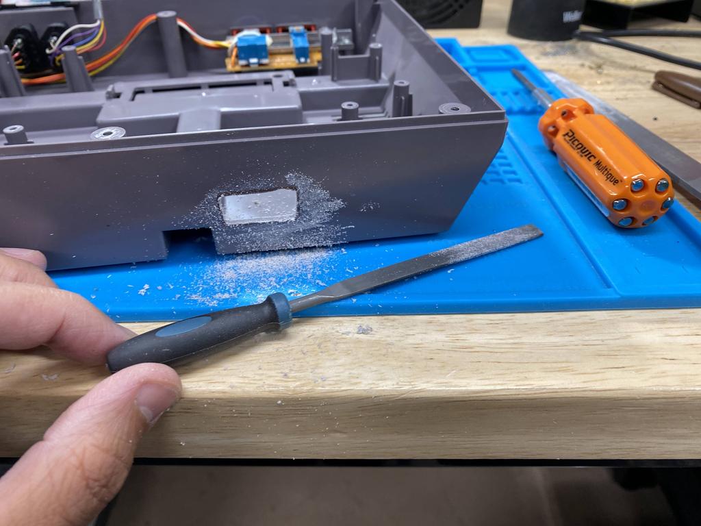
Next came the most annoying part for me, since I still don’t own a proper dremel: I used a drill, flush cutters, and filing tools to cut out the hole:
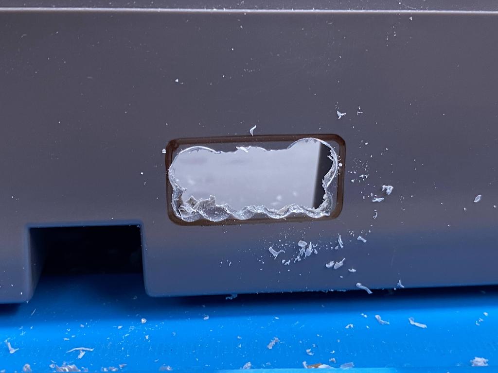

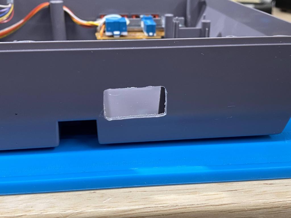
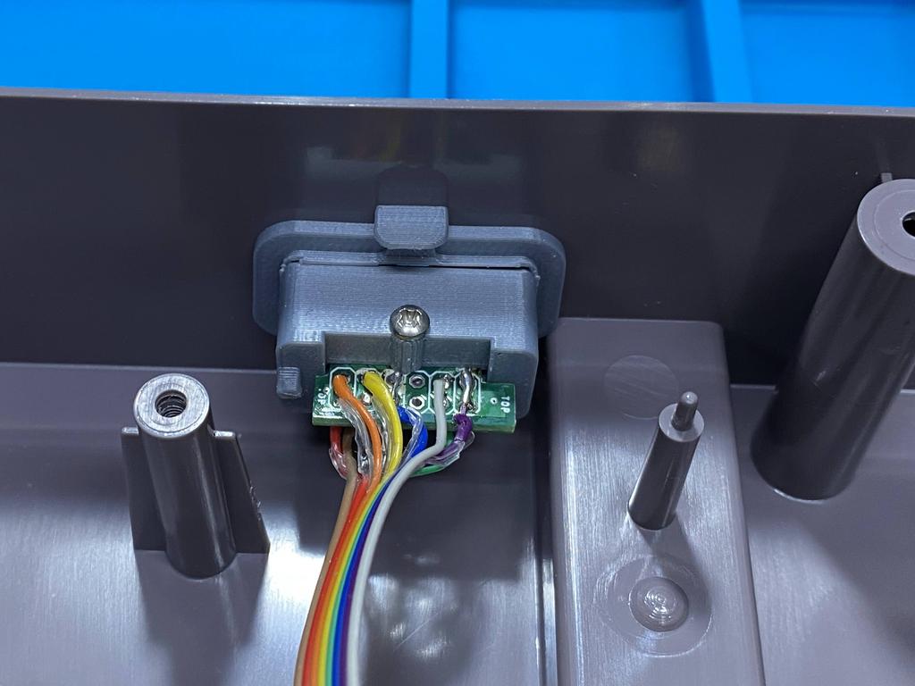
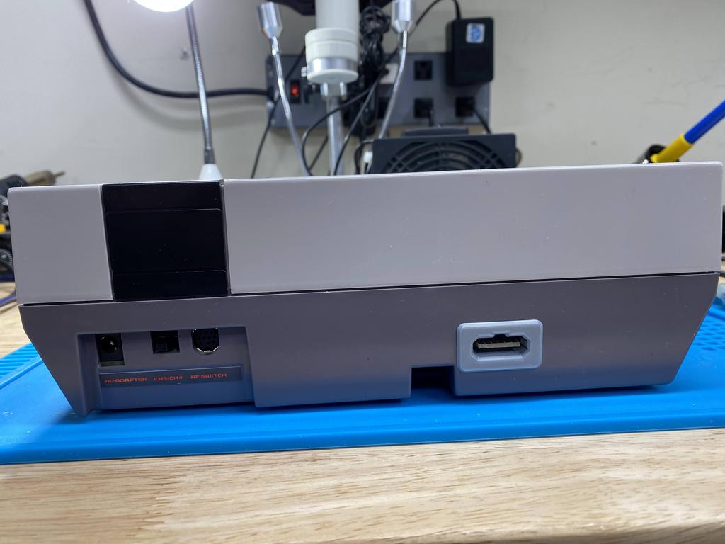
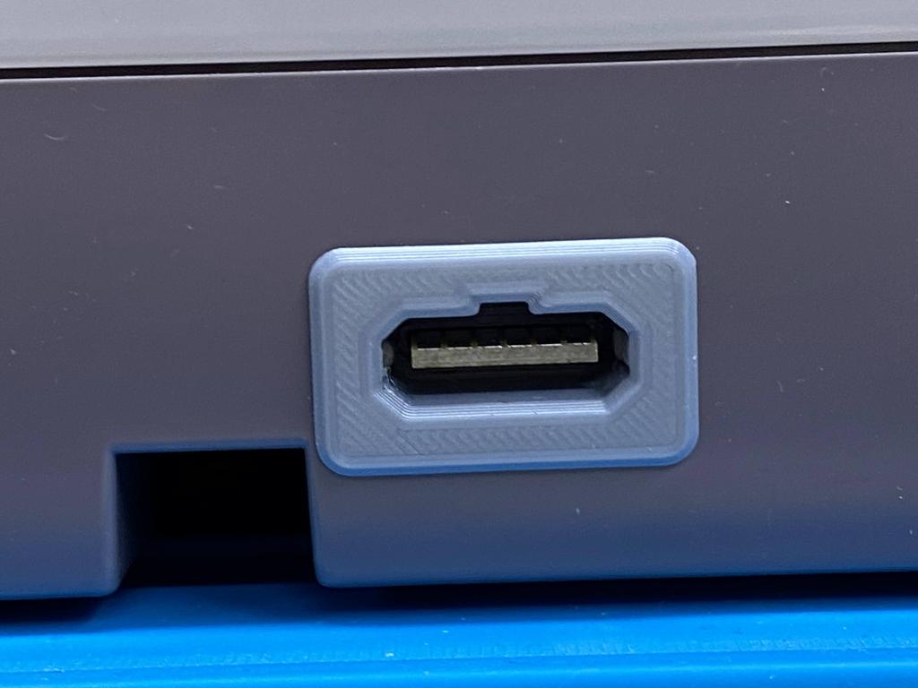
Finally, after way too long, the connector fit in perfectly:
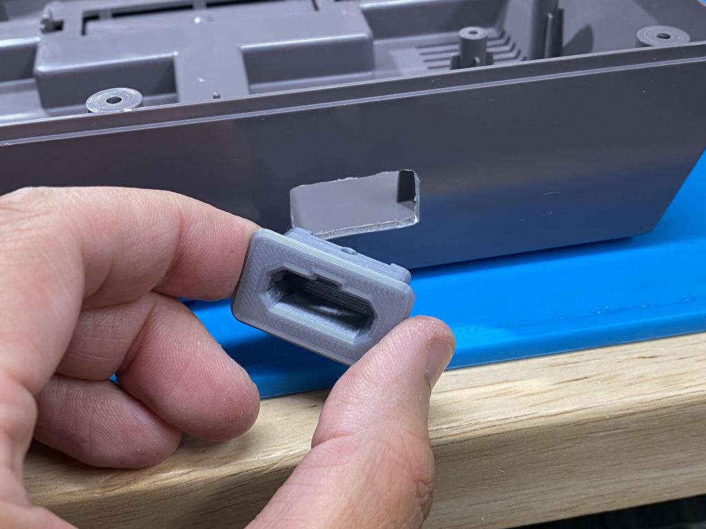
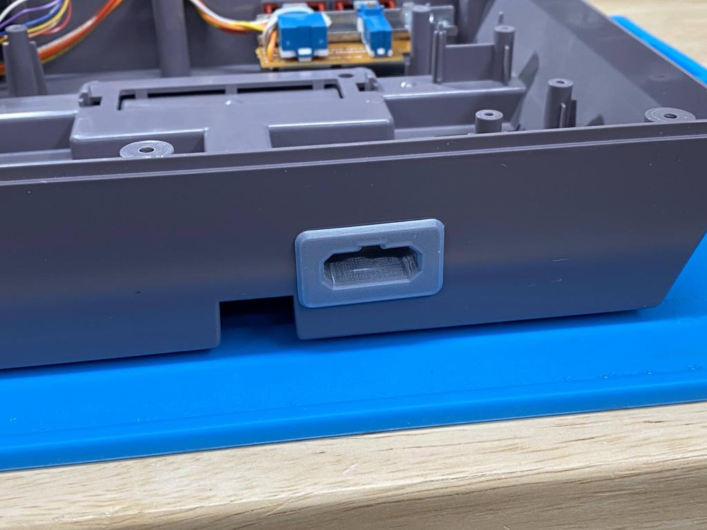
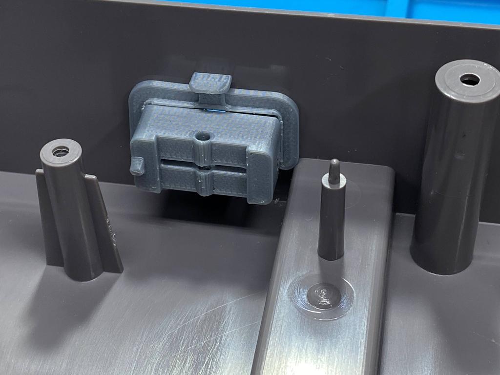
I used the 3D printed clip to hold the connector in place:
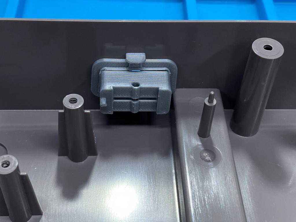
The fit was a little snug considering that raised portion inside, but thankfully it was fine:
Expansion audio #
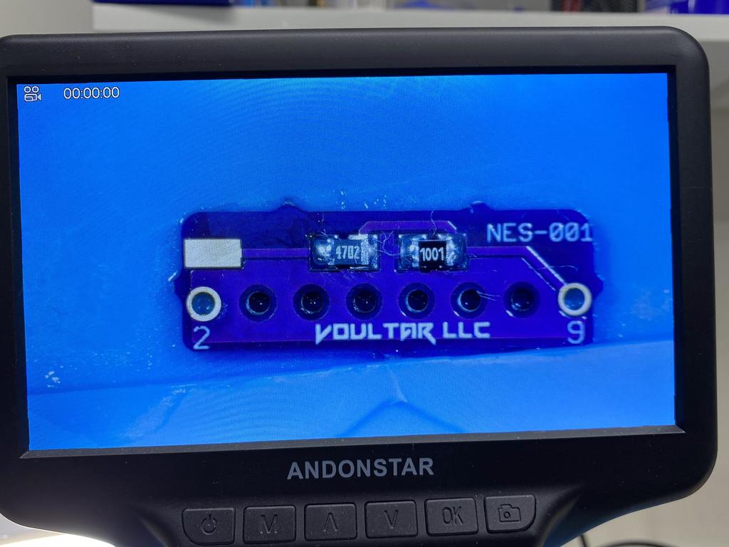
Before closing everything up, I also wanted to enable expansion audio. I decided to use Voultar’s PCB because this is what I had done for my NESRGB install. What I didn’t realize at the time was that this wasn’t necessary at all since the Lava RGB doesn’t process audio like the NESRGB. I’ll show my misteps here, and how I corrected it, but this could definitely have been simpler!
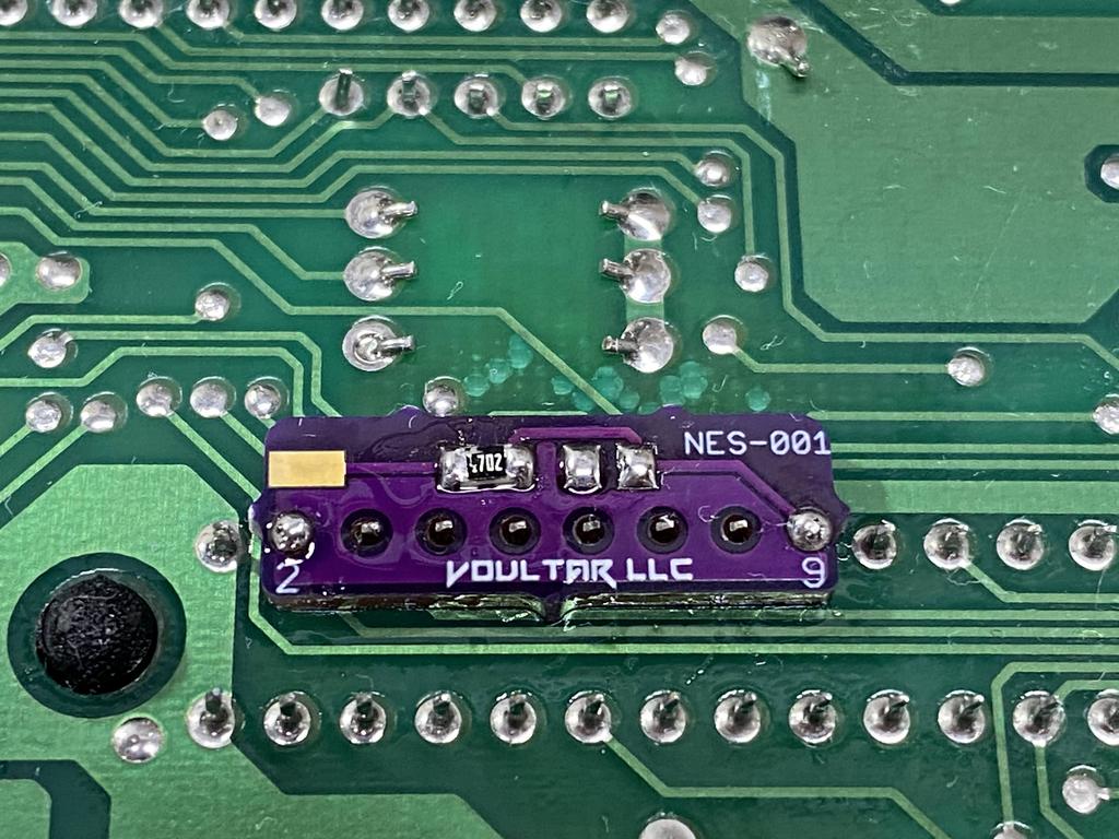
I soldered a 1K and 47K resistor to the PCB:
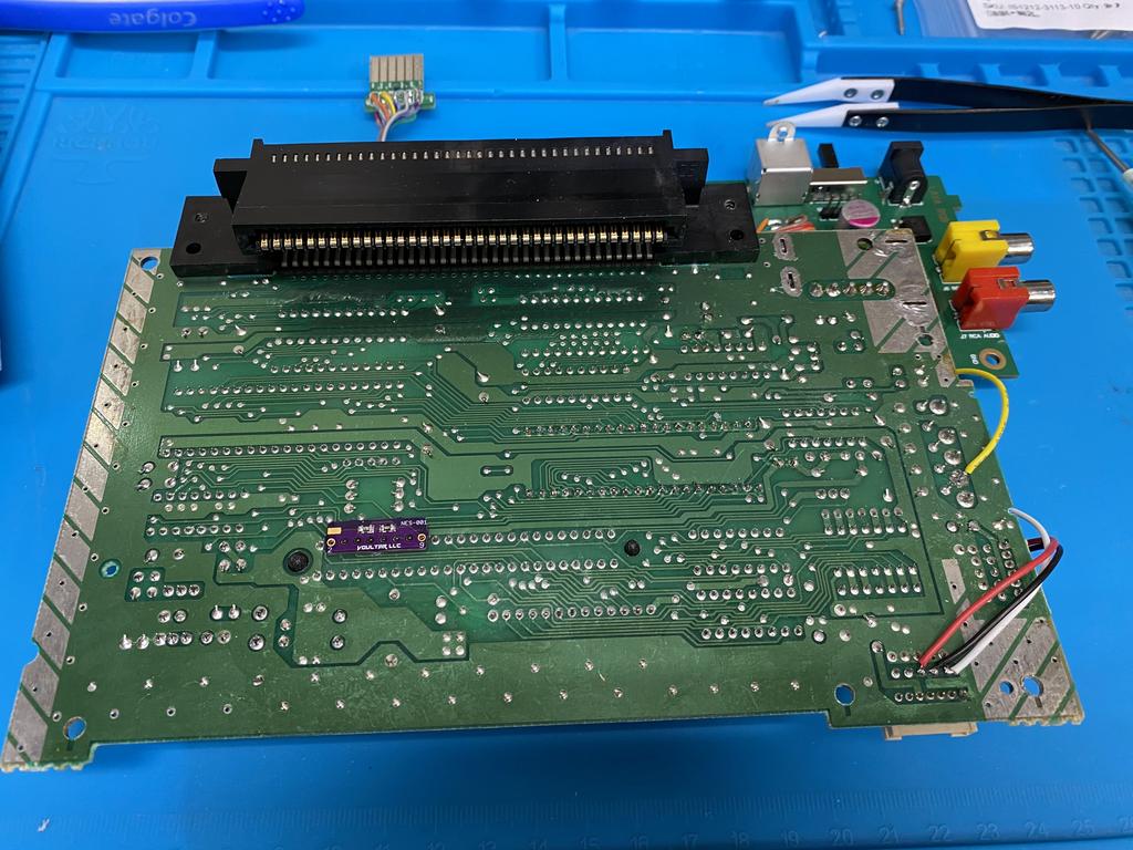
I positioned the PCB on pins 2 and 9 on the expansion port pins and soldered the PCB in place:
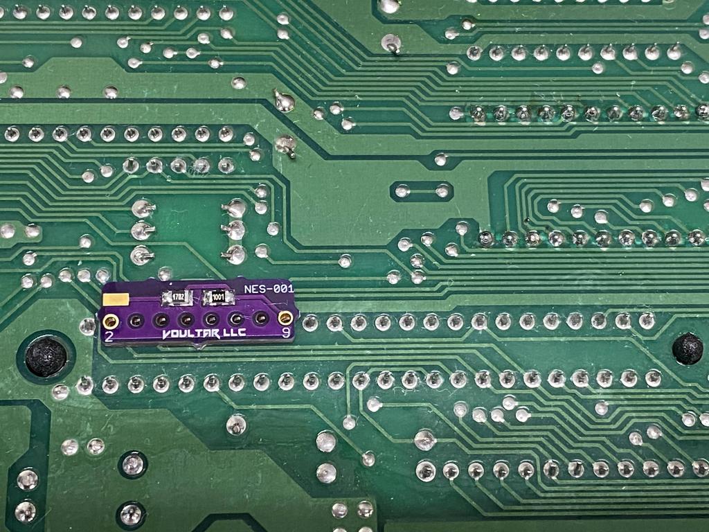
It was at this point that I tested expansion audio and realized it wasn’t working. After chatting with Toxic_Tripod0 on Discord, I realized my mistake. To enable expansion audio without NESRGB, all that’s needed is a 47K resistor between pins 3 and 9. This PCB is expressly designed to route expansion audio to the NESRGB for processing. At this point, I could have removed the PCB, but I realized I could fix this relatively easily by removing the 1K resistor, and soldering a wire from the exposed pad to pin 3:
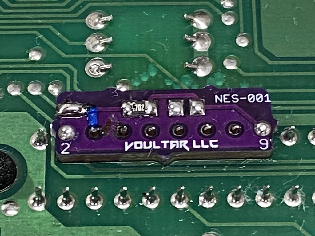
As required, pins 3 and 9 were now connected via a 47K resistor:
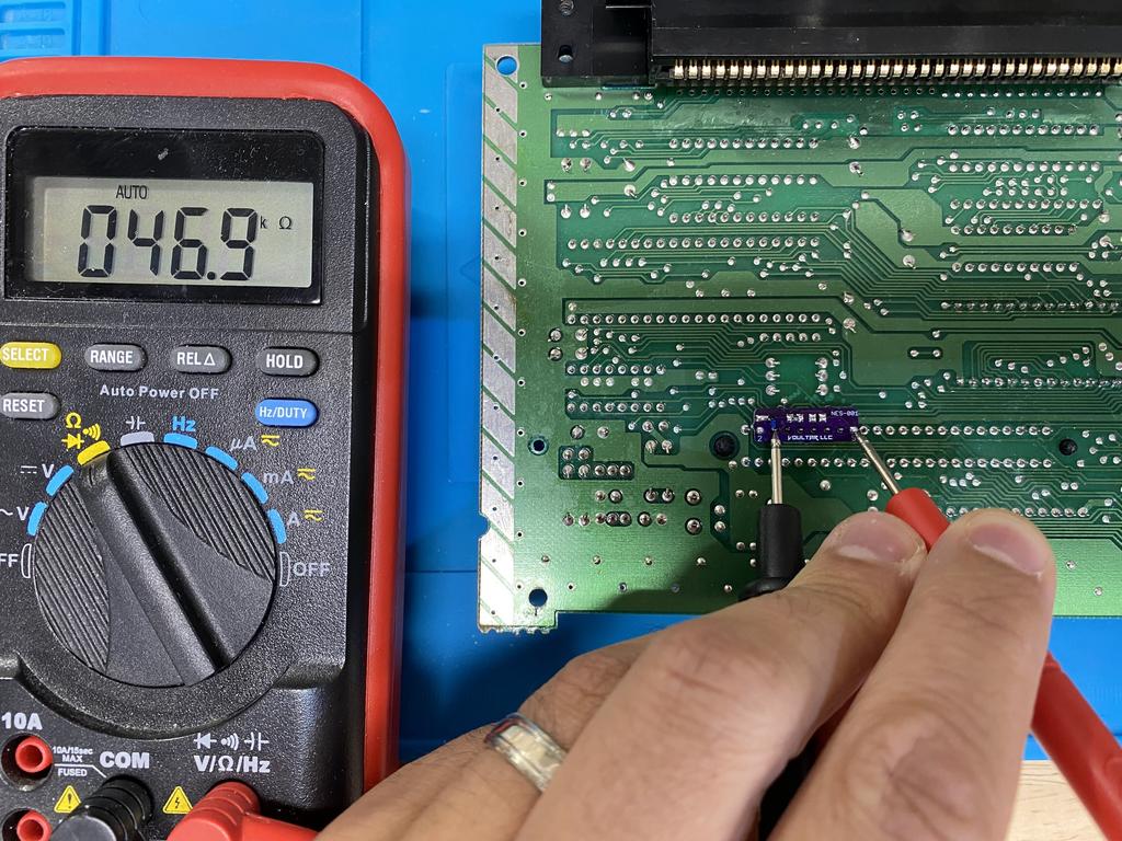
I tested expansion audio, and it worked! If I were to redo this, I’d probably just connect a 47K throughole resistor between pins 3 and 9 instead.
Closing everything up #
It was finally time to put everything back together:
I attached the power and controller cables to the main board:
I inserted the multiout PCB into the connector and screwed it in:
I reattached the cartridge slot to the main board, and carefully inserted the main board into the bottom shell. The new power module is only held by those 5 pins to the main board, so some care has to be taken when fitting it in place:
I decided not to put in the RF shielding as it’s not really necessary, and would pinch and possibly short the reset and controller 1 wires used for IGR and palette switching. I put in all the screws, including the ones in the posts used for the RF shielding:
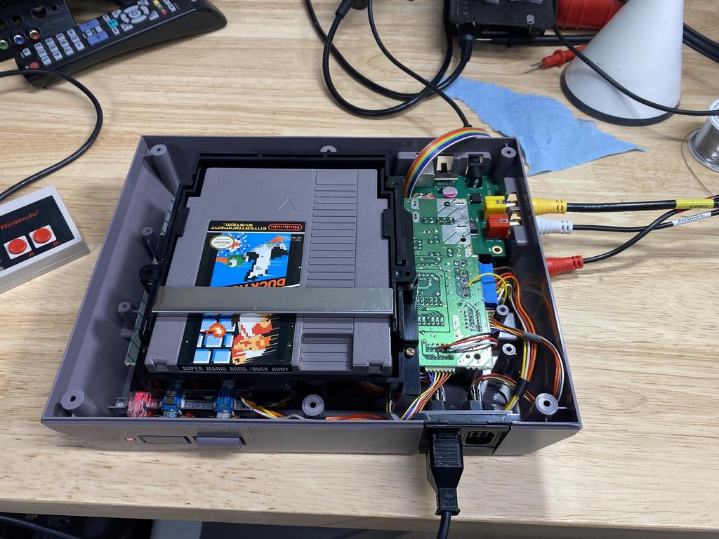
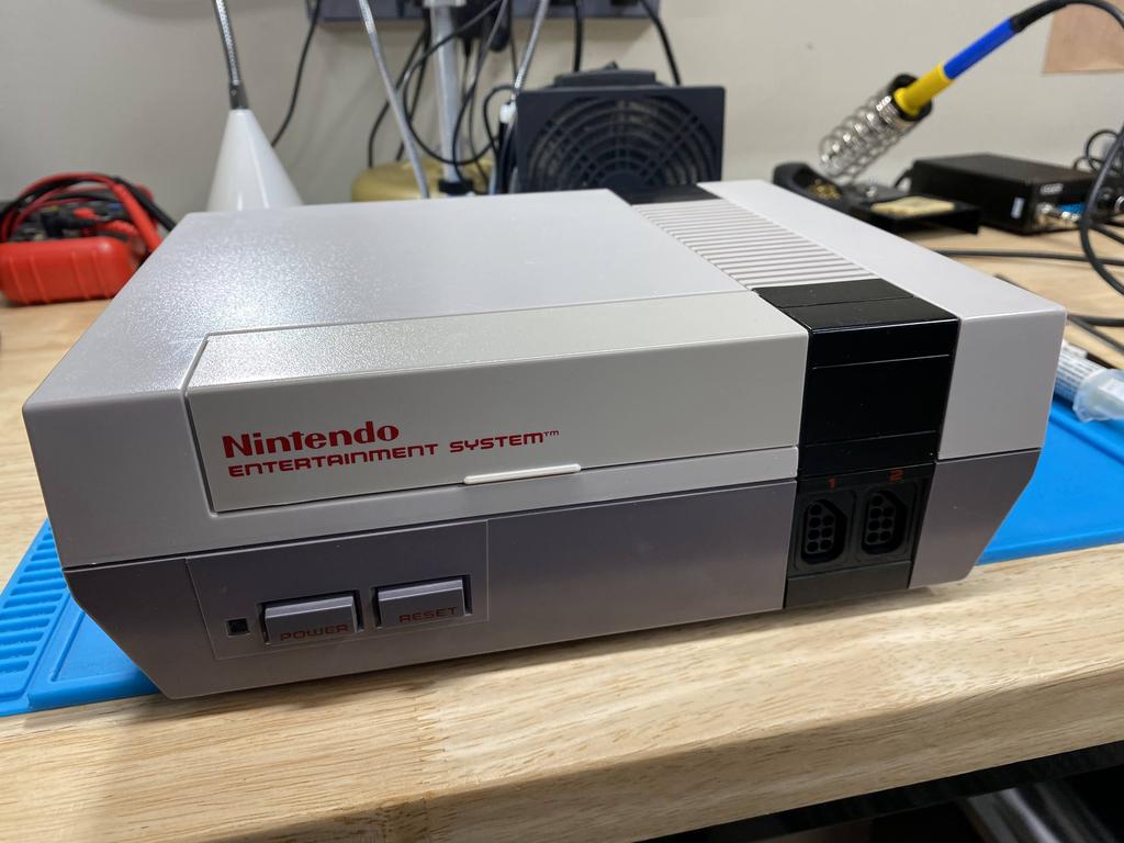
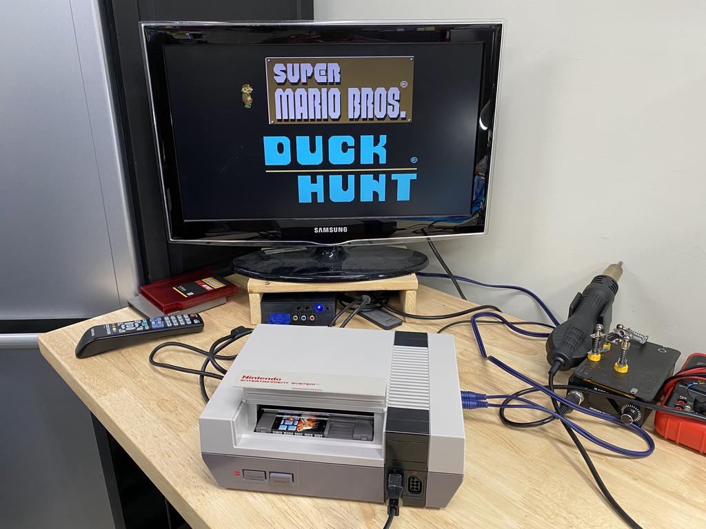
I screwed on the top shell, and was finally done! Here it is in all its glory:
Final test #
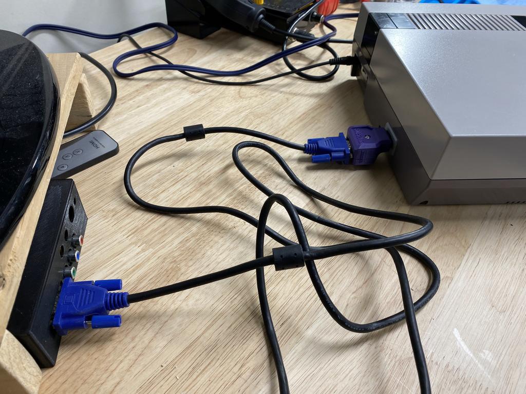
With everything back together, I hooked it up using my SNES2VGA with a VGA cable to my gbs-control:
Looking good in RGB:
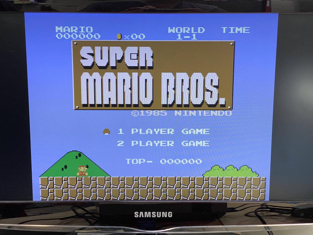
Interestingly, the colors don’t exactly match the composite output:
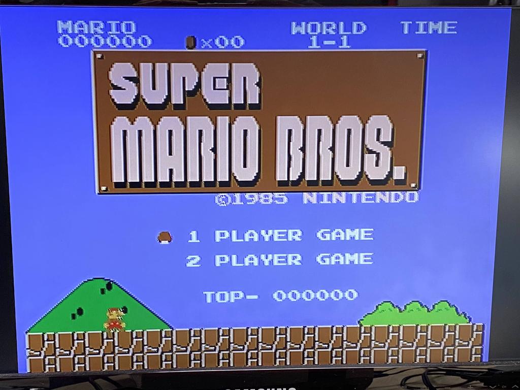
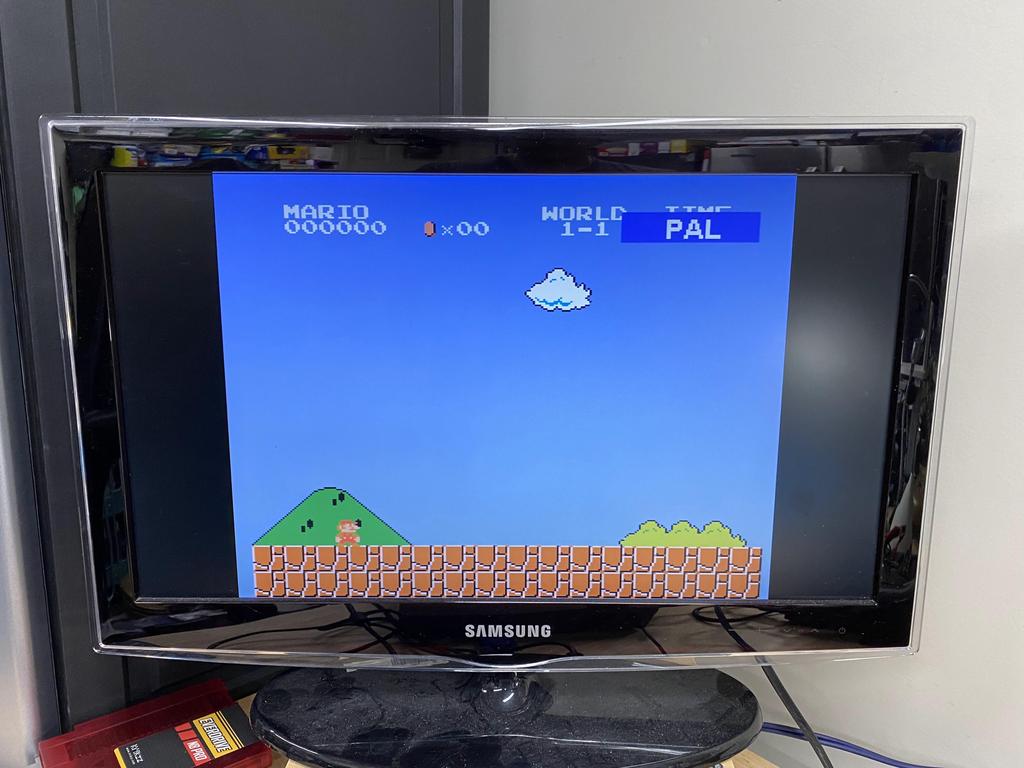
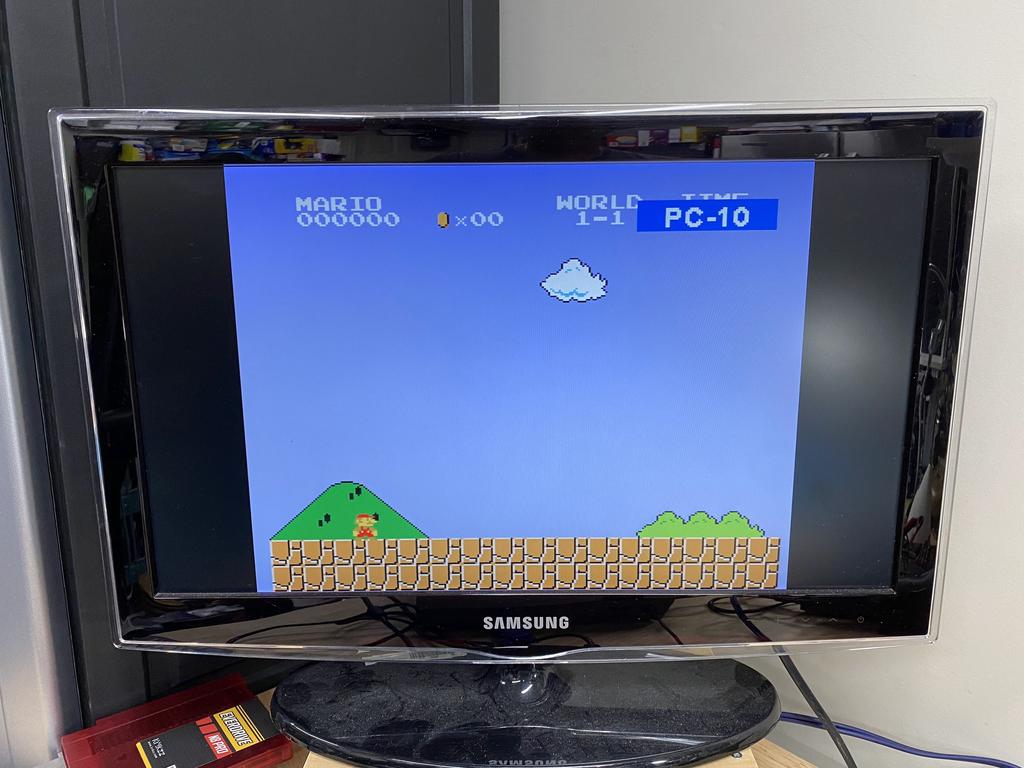
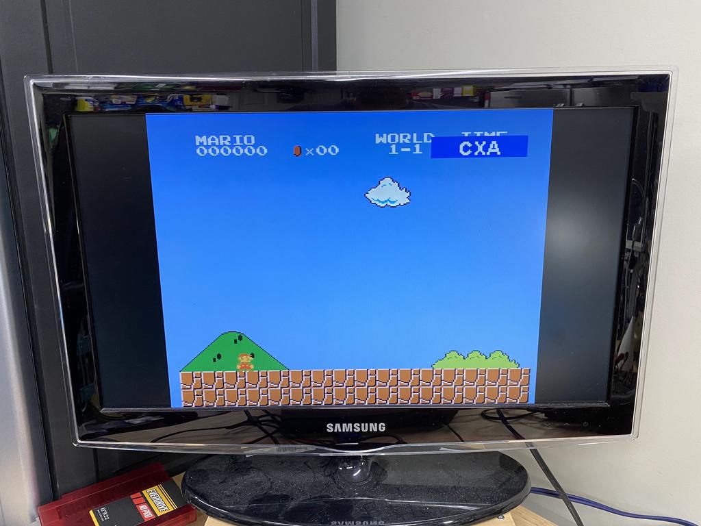
Using the palette switching control (hold select + Up on dpad), I cycled through the palettes, which displays the name of the palette for a few seconds. Here are some samples:
Thoughts #
I’ve been playing with this modded NES for a few days now, and it works and looks great. The Lava RGB 2.0 is definitely a worthy contender to the NESRGB, especially for the price. Although it doesn’t process audio, tapping the NES-produced audio out from the new power module works fine, and the sound is very clean.
It’s worth noting that this mod doesn’t require the new power module at all, especially in my case as I added the SNES-style multiout. However, for those who don’t want the multiout, and want a no-cut mod, this is a nice way to do it. In my case, the power module made it easier to wire up the multiout, and possibly improved the audio output as the older power modules are known to add interference to the audio signal.
I just wanted to give a quick shout out to the folks on the ConsoleMods discord, especially Toxic_Tripod0, manadream, and RobStrange for their help.