PS1 15Khz "VGA" Mod
A while ago, I modded my PS1 with the PsNee, which was really great, but one thing that I wanted to improve was the video output quality when playing on my modern TV. The PS1 natively outputs composite video by default, and can output RGB, but you need to buy an expensive cable to access it. At some point, I stumbled upon this blog post by Wesk that describes how he modded his PS1 to output 15Khz RGBHV via a DE-15 VGA-style connector. This would be perfect for me as the gbs-control scaler I built can accept such a signal.
Plan #
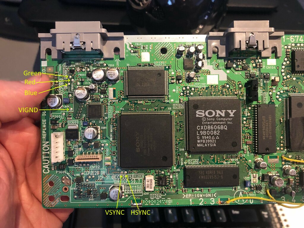
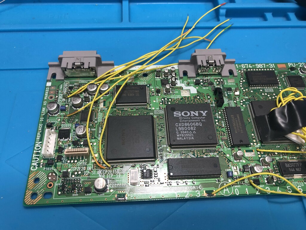
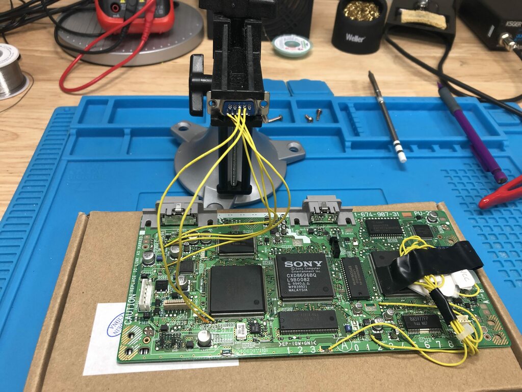
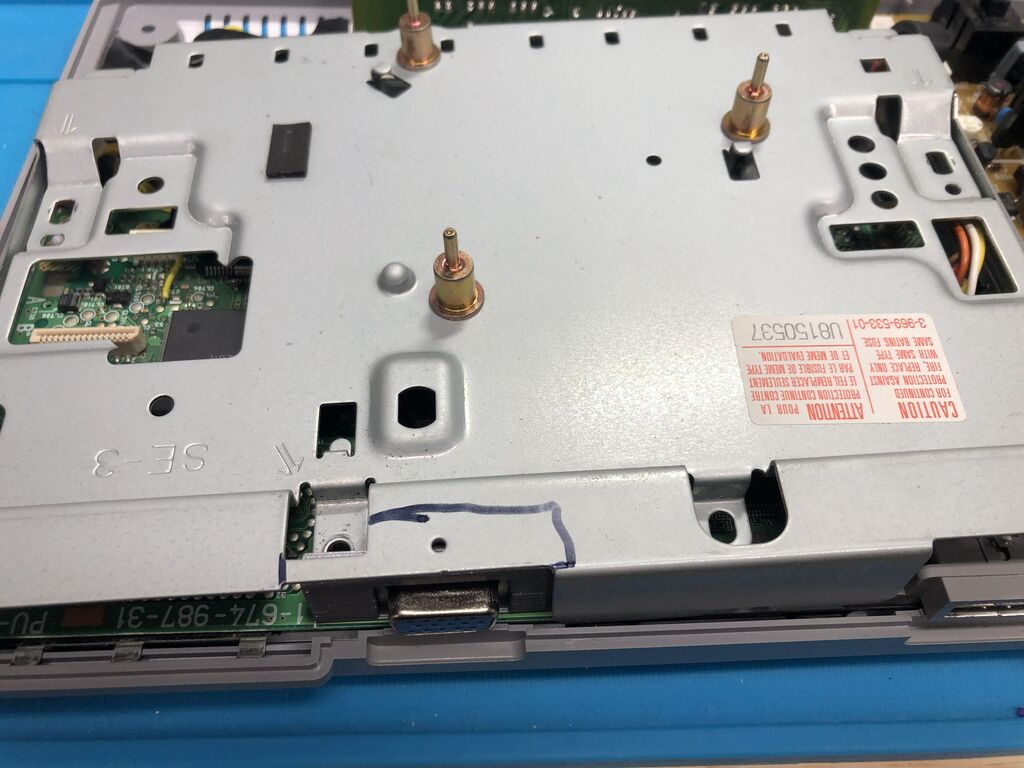
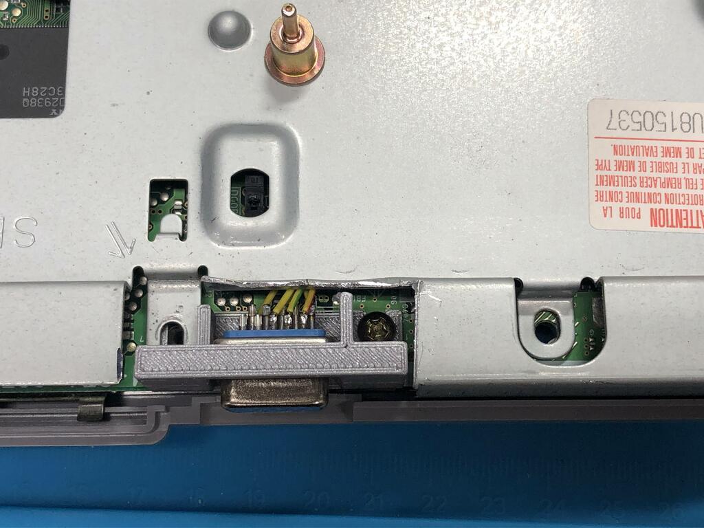
While waiting on the pack of 5 VGA connectors I ordered from AliExpress for about $7, I opened up my PS1 to determine where I’d need to solder to. Wesk’s PS1 in his post is a model SCPH-5502, while mine is a SCPH-7501 (PU-23), so the layout is not the same. I took a photo of my board, and using this service manual, I marked the points I’d need to tap into:
The Build #
So now it was time to solder wires to the board. Note that in Wesk’s post, he uses coaxial wires for the RGB signals to shield them from noise. I didn’t have any coax wires, so I decided to just use regular wire and see what happens.
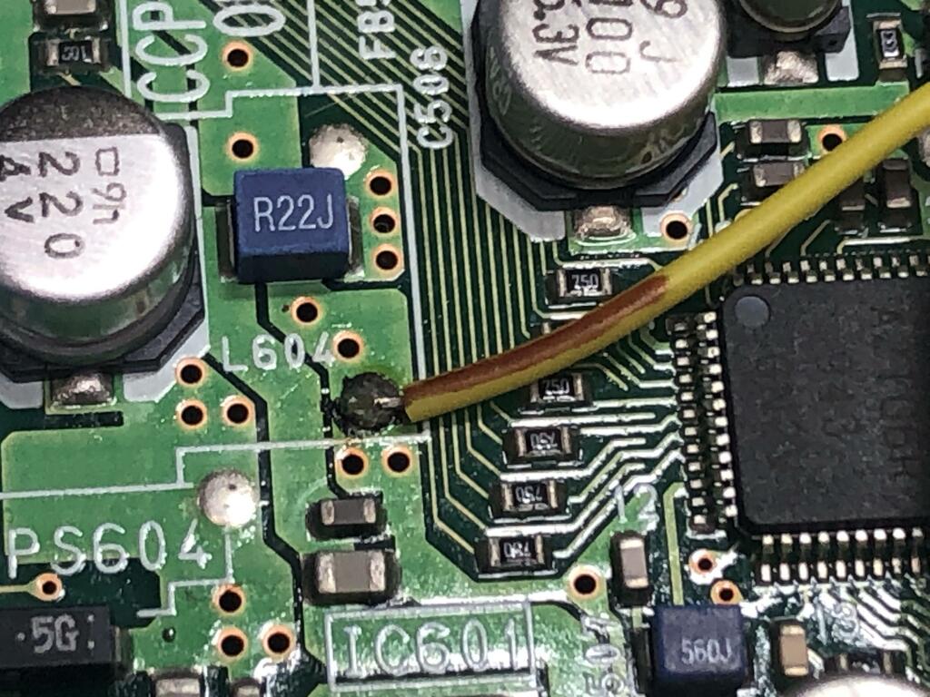
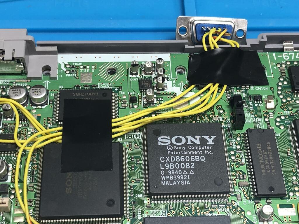
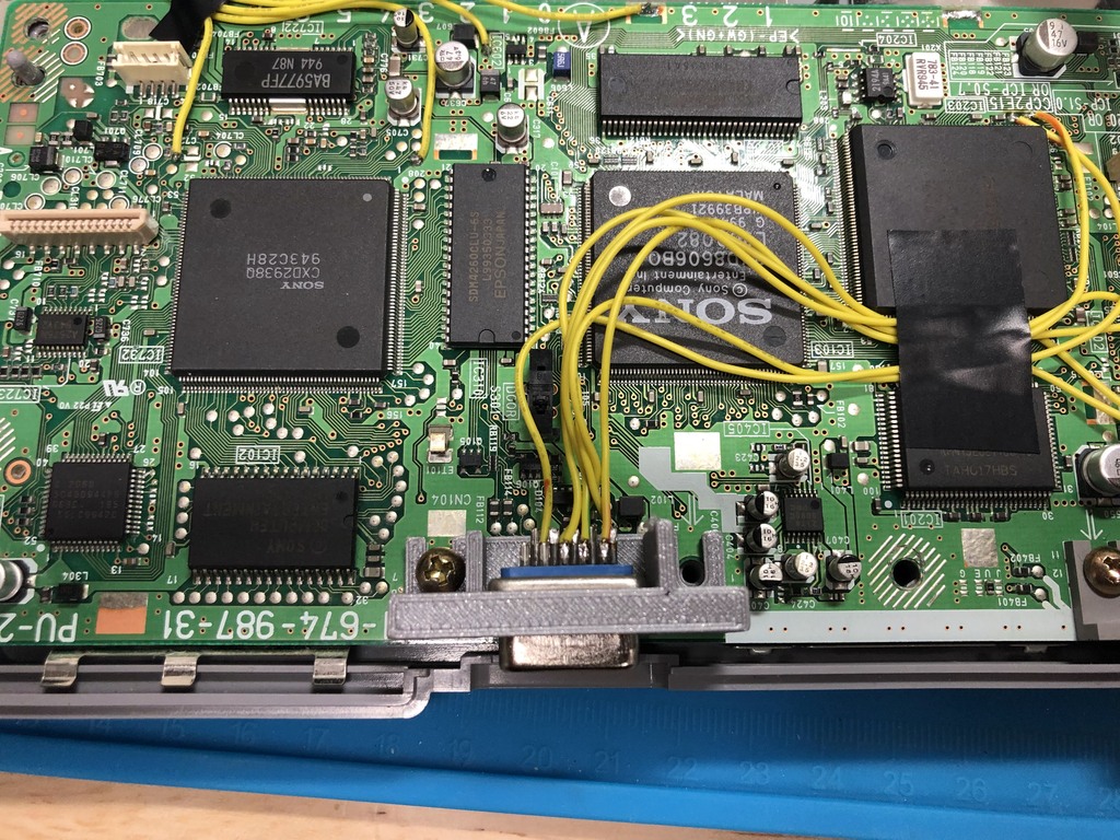
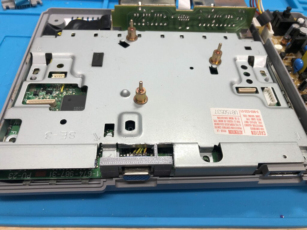
Using my marked up photo from above, I went ahead and soldered six wires.
Three for RGB:
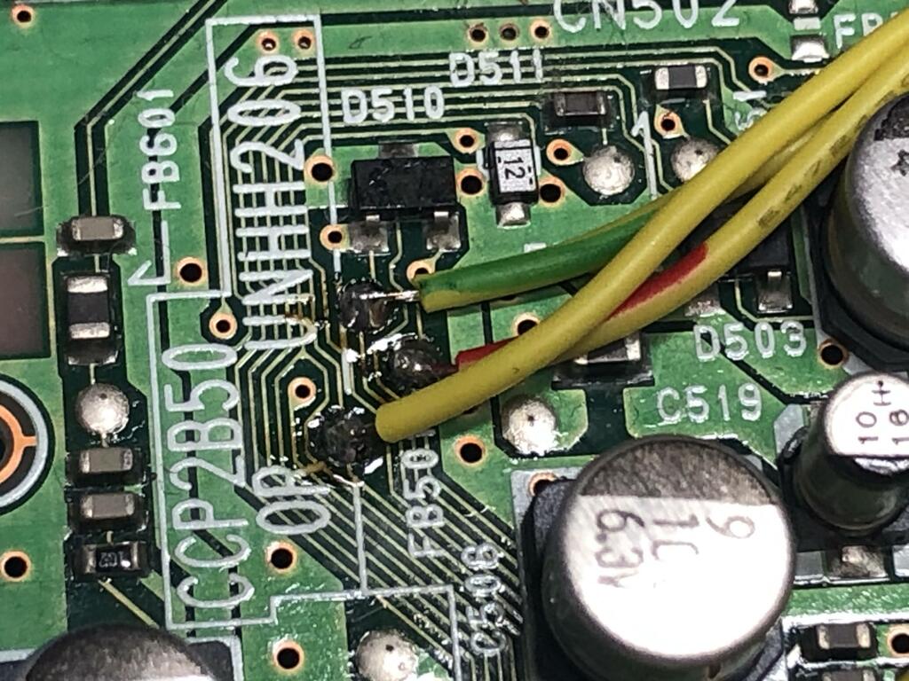
One for ground:
And two for horizontal and vertical sync:
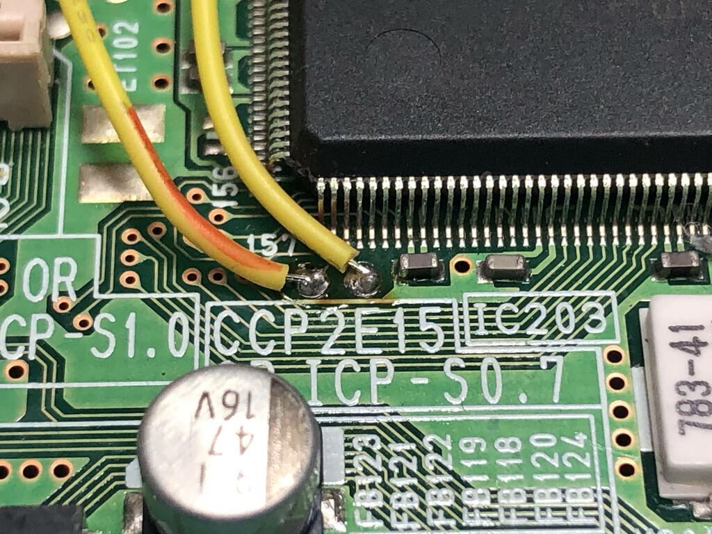
All together it looked like this:
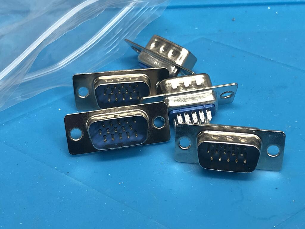
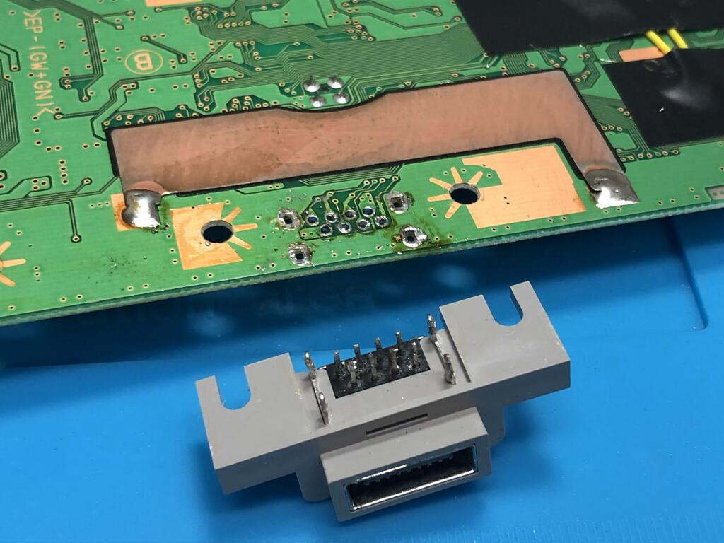
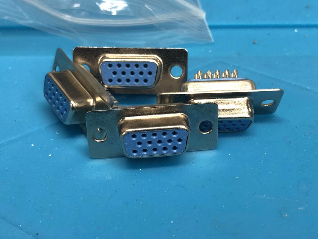
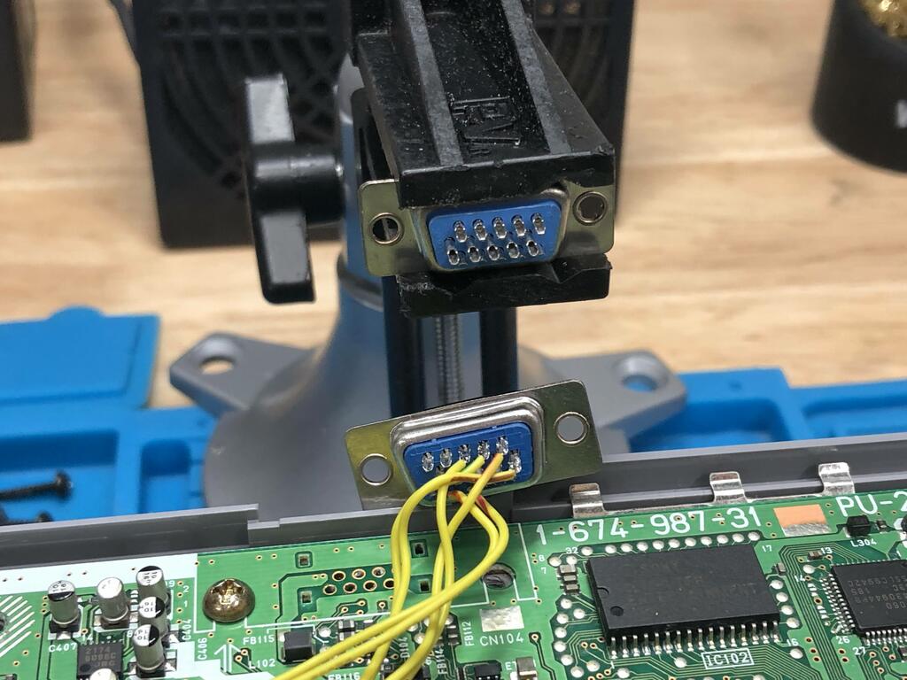
Once I received the VGA connectors, I realized I had made a mistake! Instead of ordering female connectors, I had ordered male ones:
Oops! I went ahead and ordered the correct ones from AliExpress, and while waiting, I realized I owned a VGA extension cable, which has one male end and one female end, and that I could use it with a male connector. So being impatient, I decided to temporarily move ahead with the male connector and extension cable, and replace it later with the female connector and a regular VGA cable.
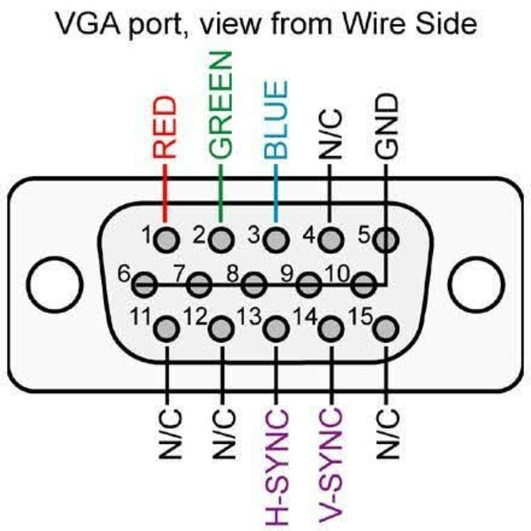
Someone on original post shared this useful pic of where to solder to the VGA connector:
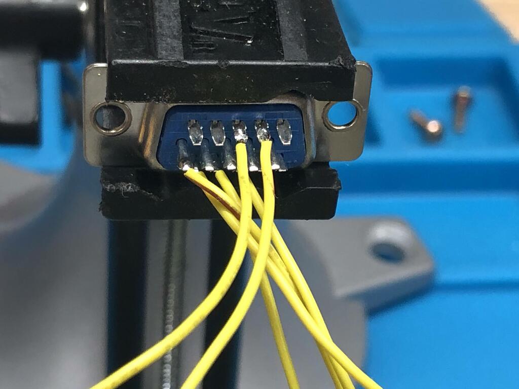
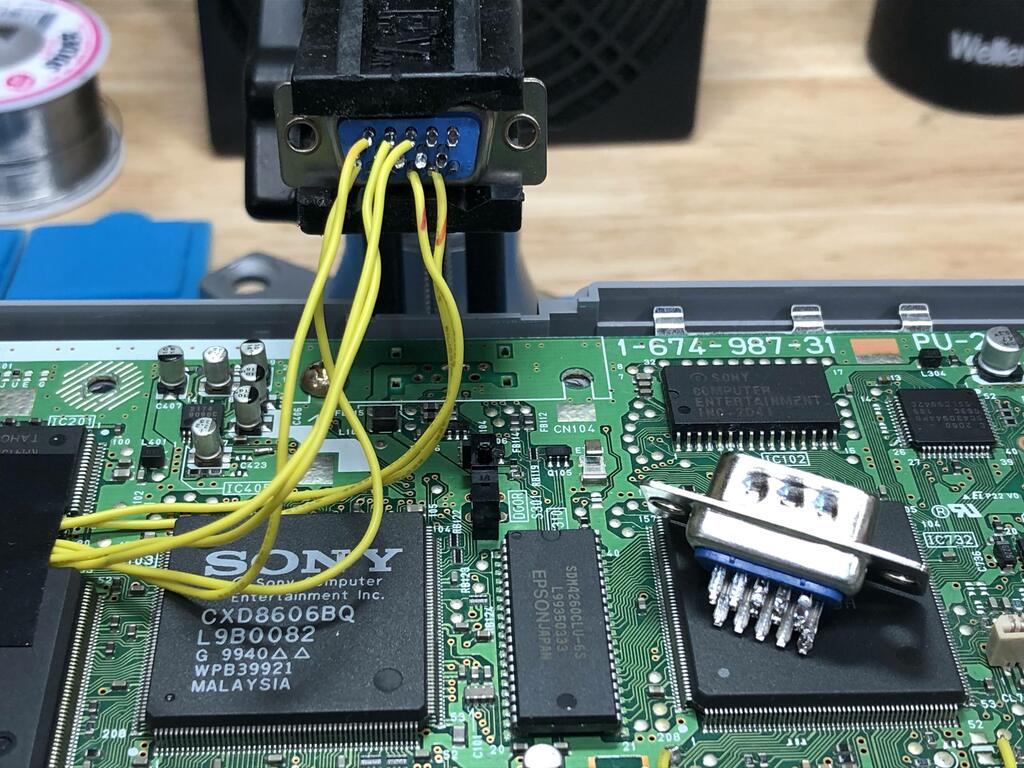
Since I was using a male connector with an extension cable, I needed to mirror my connections horizontally. I soldered the wires to the connector:
And now it was time to test it. I hooked up the extension cable into the gbs-control with HDMI out to my TV:
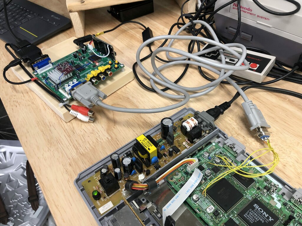
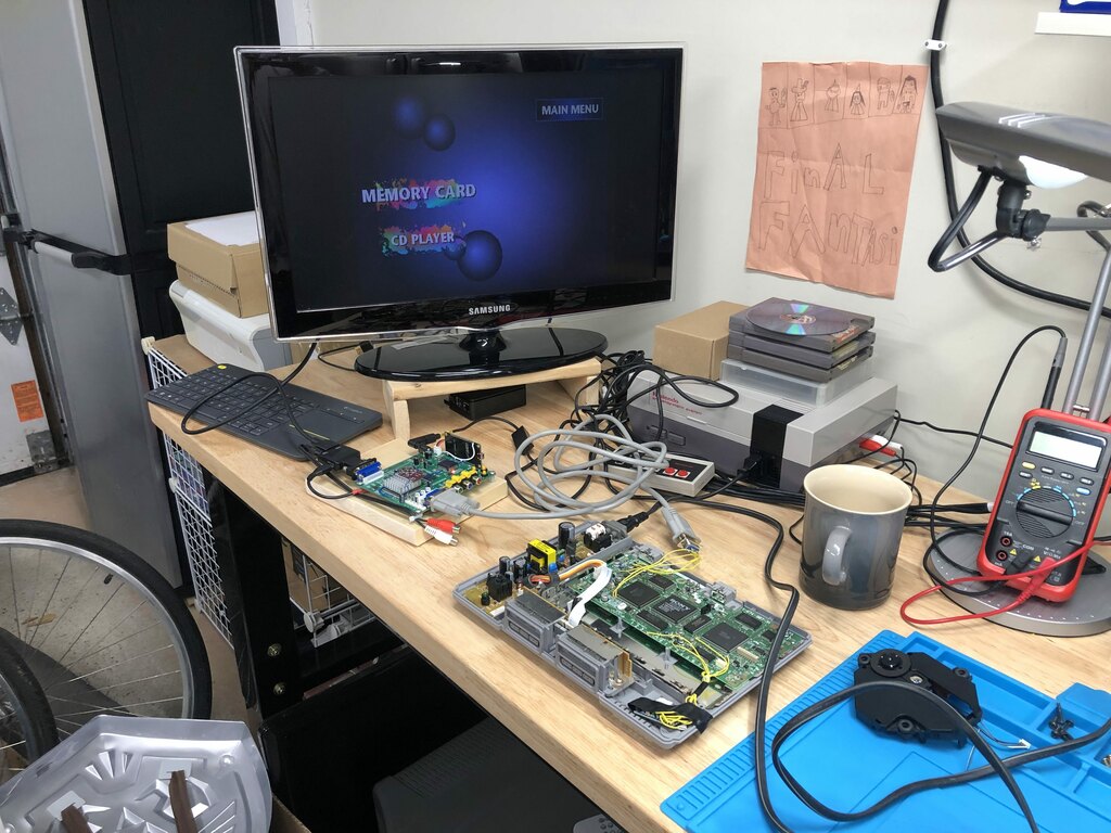
Success!
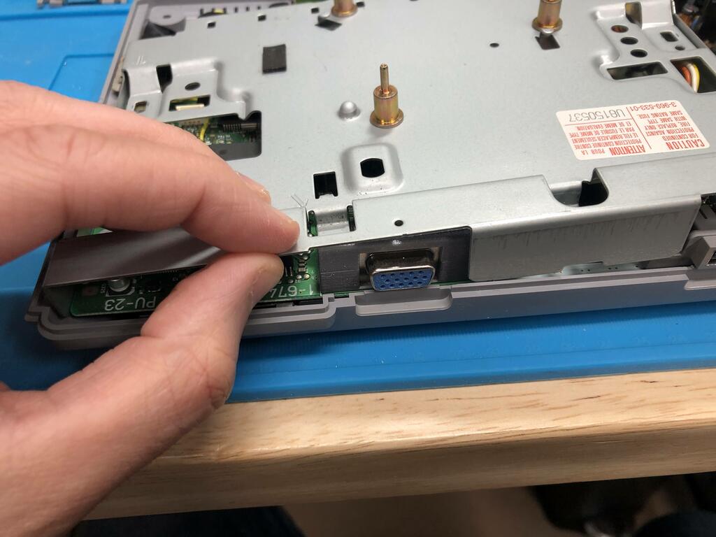
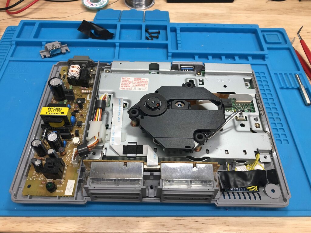
Next, using my desoldering gun, I desoldered the serial port from the PS1 to have a place for the VGA connector:
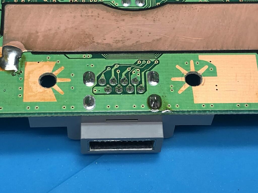
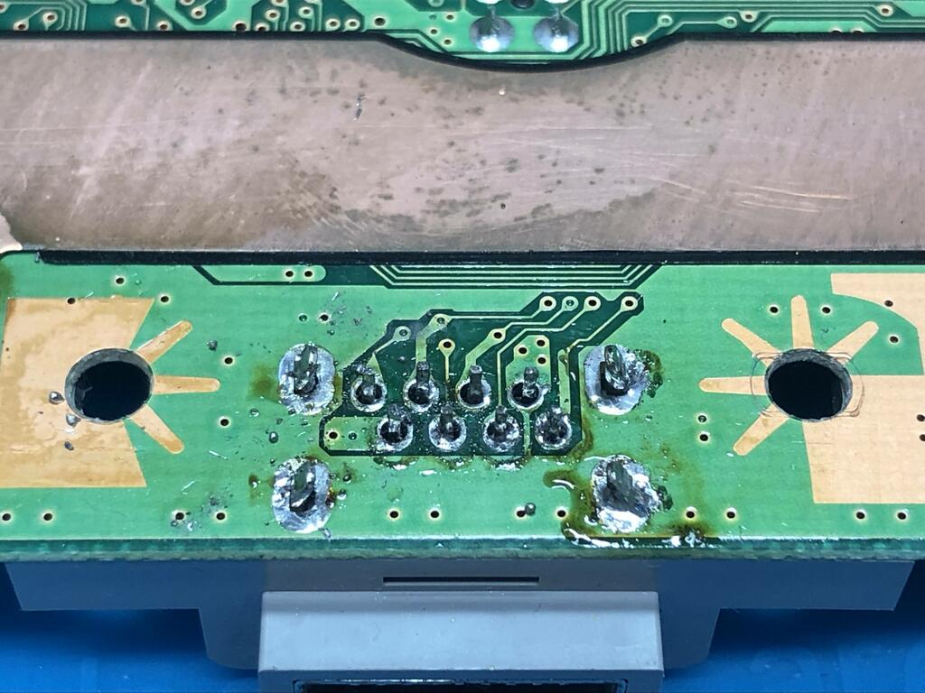
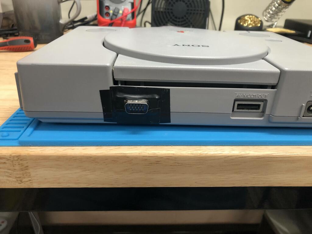
Since I was waiting on the female VGA connector to finish up, I left the connector hanging out of the serial port slot with some wire tape to keep it roughly in place:
A couple of weeks later, I received the female connectors from AliExpress:
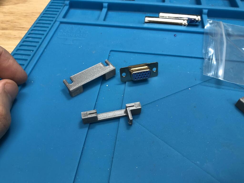
My friend also 3D-printed the bracket designed by Wesk to hold the connector in place:
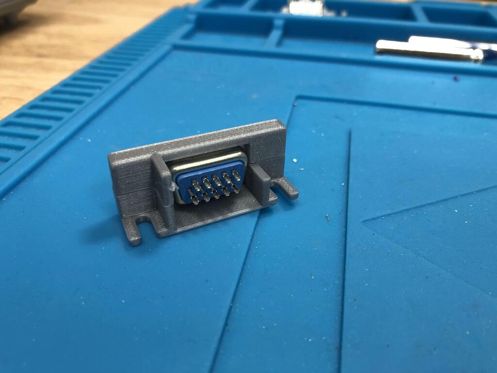
I opened up the PS1 again, and desoldered the wires from the male connector and soldered to the female one, mirroring the connections horizontally:
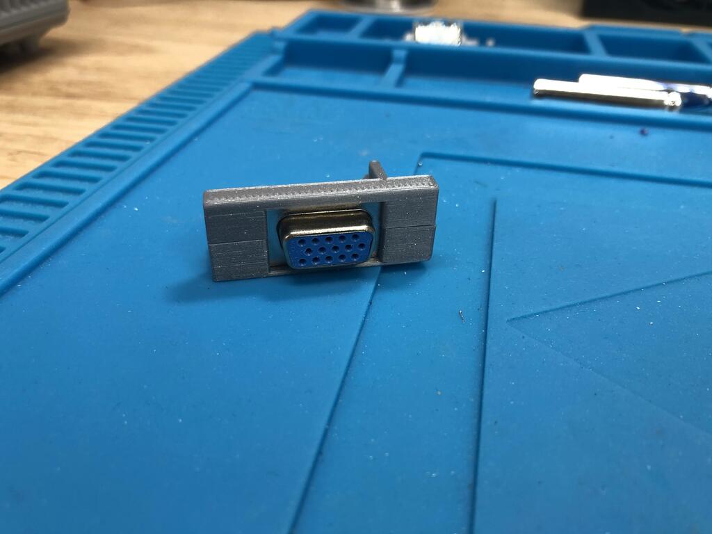
The 3D-printed bracket fit perfectly:
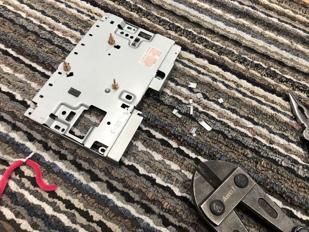
But like Wesk describes in his post, the RF shield needs to be cut to allow the bracket to fit. I don’t own a Dremel (yet), so I used some large cutters and pliers to cut the shield:
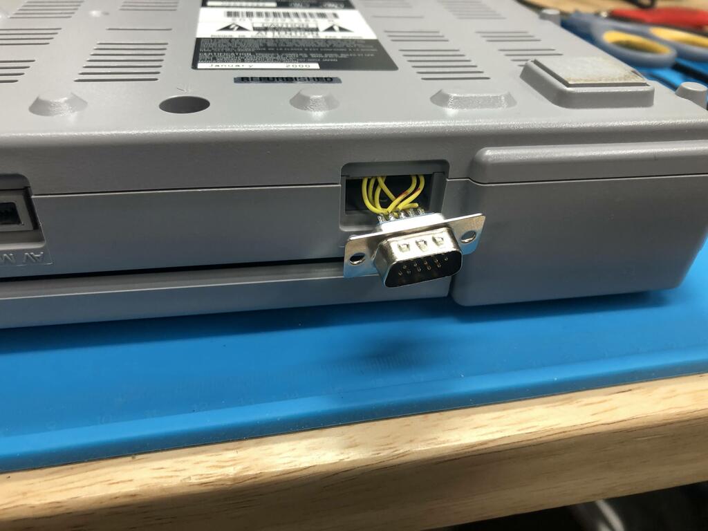
Perfect fit! Now I could button up the console:
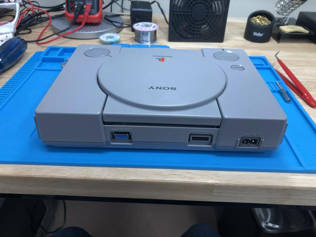
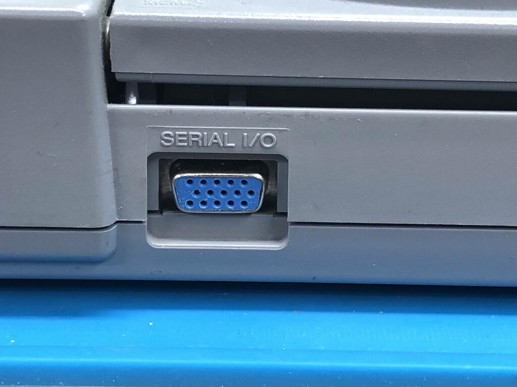
It looks almost stock when all closed up! I will say, though, that when connecting a VGA cable, it doesn’t go all the way in; however, there’s enough of a grip on the pins that it’s not really a problem. It’s worth mentioning that this only outputs video, so you still need to connect the regular multiout cable to get the left and right audio signals.
Comparison shots #
What’s cool about this mod is that you can still output the composite signal at the same time as the RGBHV signal. I took some photos of my TV with my phone to compare the two (left is composite, right is RGBHV):
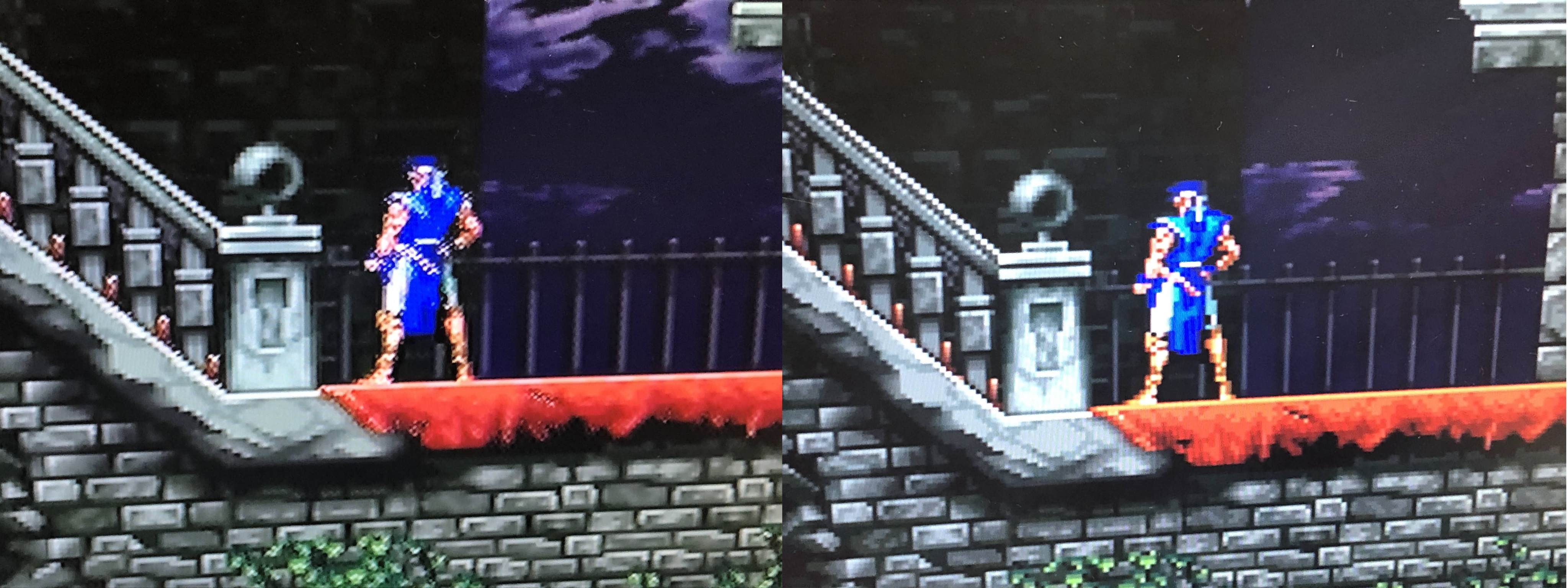
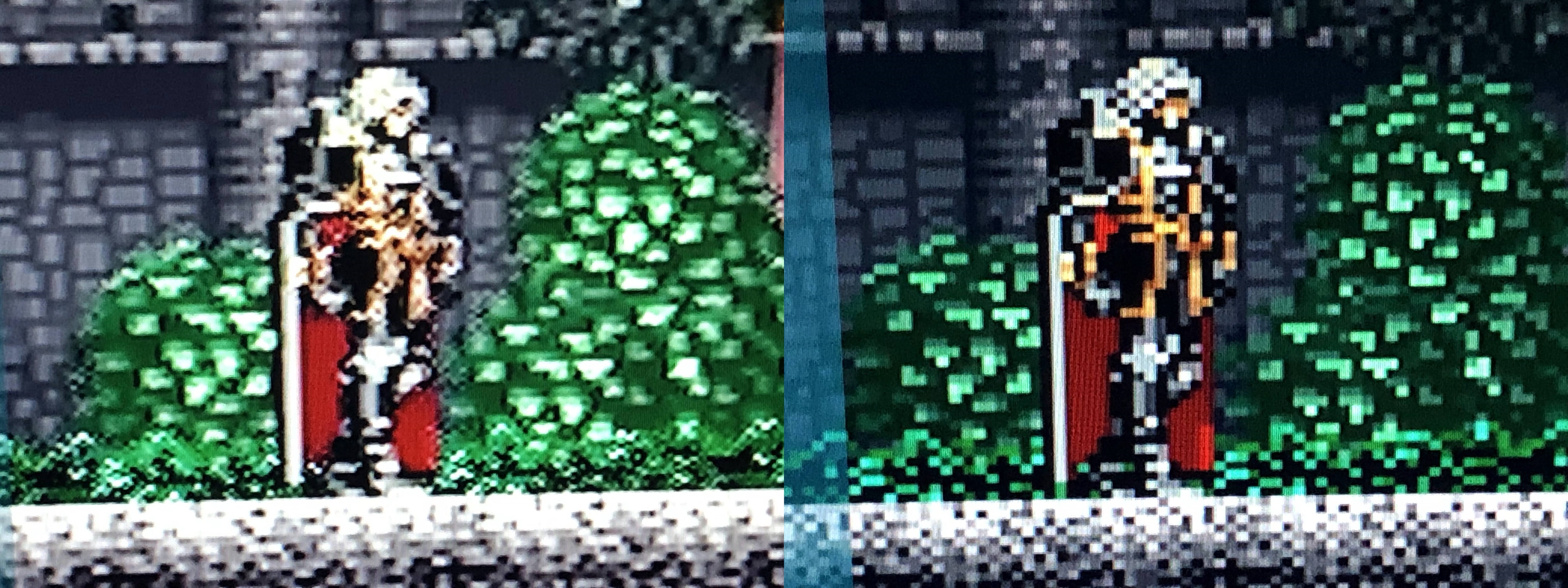
The difference is really obvious. The RGBHV output is clean and crisp, and perfect for playing on LCD screens.
Thoughts #
This was a fun mod, and not too difficult. I definitely recommend it if you don’t want to spend a lot of money on component cables for the PS1. I’ve been playing a bunch of classic PS1 games on my 70” TV since I did this, and am loving it!