Adding "VGA Audio" to my gbs-controls
In my recent post about my build of the SNES2VGA dongle, I mentioned how the dongle exposes the stereo audio signal in two ways: from the headphone jack, as well as via two unused pins on the VGA port, which I’m dubbing VGA audio. In this post, I’ll share how I modified my two gbs-controls to extract these audio signals from the DB15 port.
My Setup #
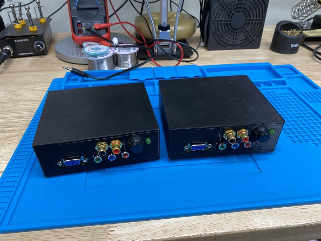
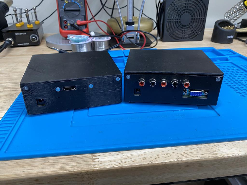
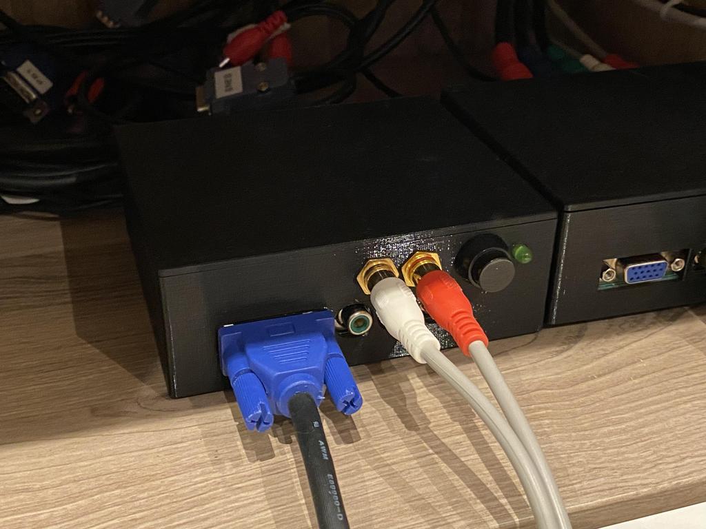
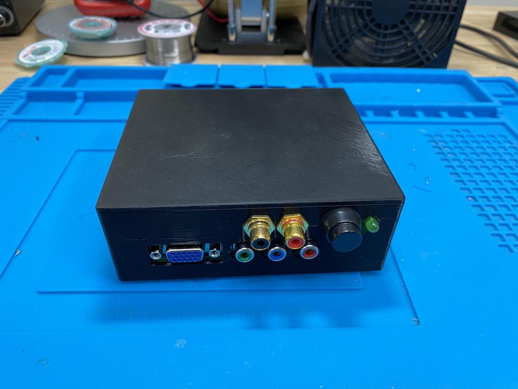
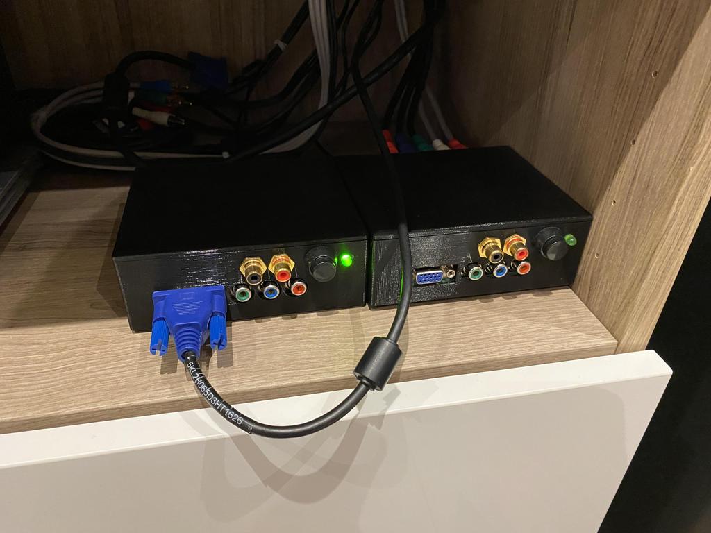
As a reminder, I have two gbs-controls, one that I use to output HDMI to my modern LCD TV, and another that outputs YPbPr to my CRT:
Before making the SNES2VGA dongle, I used these custom cables that I made to connect my SNES and N64 to my gbs-controls:
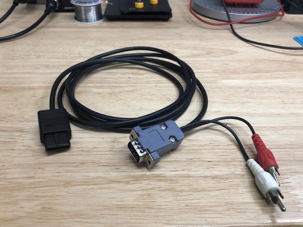
This worked, but as I wrote last time, making these cables was fiddly, the connections weren’t great, and the audio RCA connections were starting to flake out on me recently.
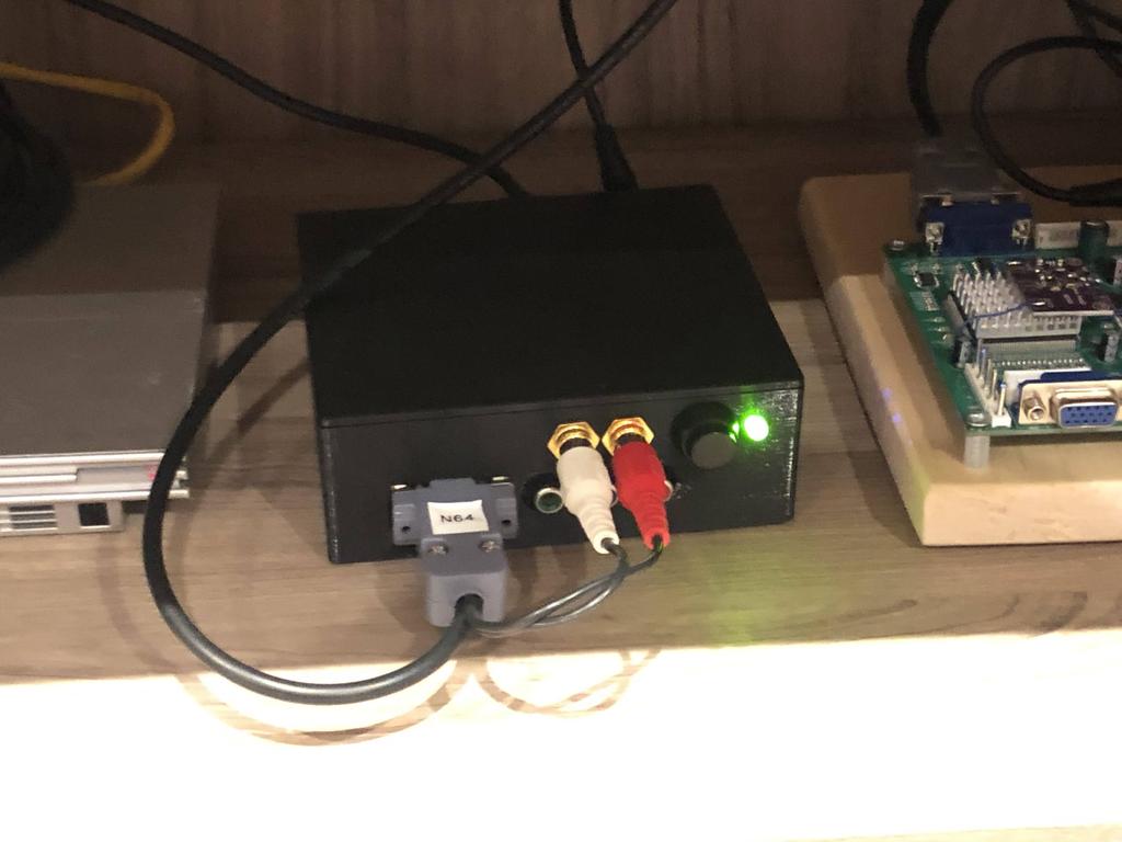
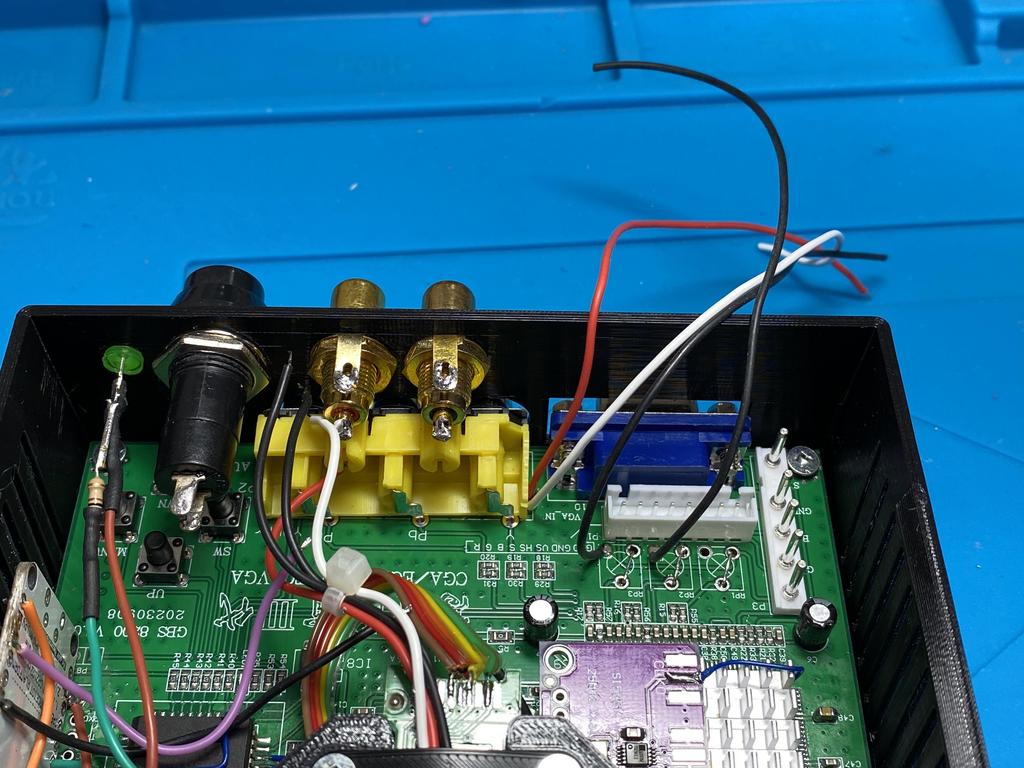
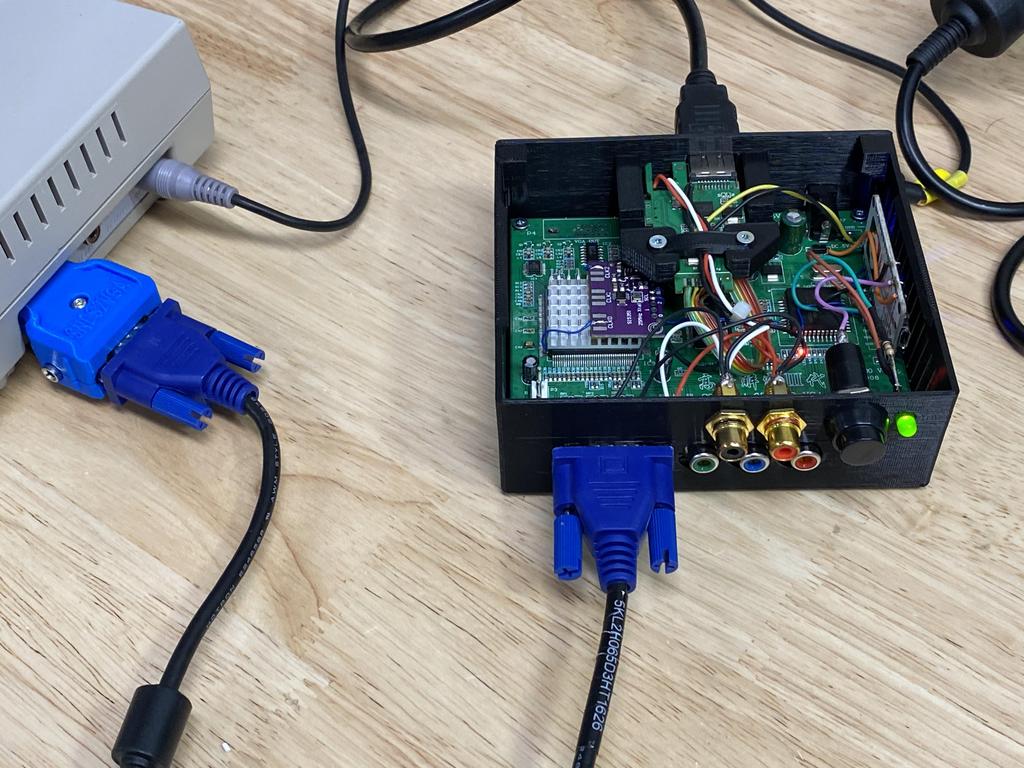
With the SNES2VGA dongles, I can now use nice, solid VGA cables to pass the video signal through, but I’m forced to also use a stereo RCA cable to pass the audio signal from the dongle to my gbs-control:
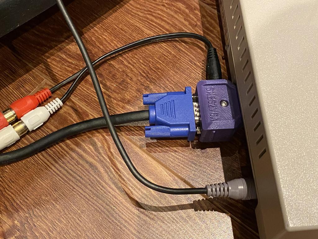
The idea is to get rid of that audio cable altogether by taking advantage of the signals that’s being passed through the VGA cable.
The Build #
The SNES2VGA PCB passes the left and right audio signals via pins 12 and 15, respectively. Note that this isn’t clearly explained on Jeff’s SNES2VGA page, but it appears in his other guides, such as for the PS2VGA.
So the plan is simple: tap pins 12 and 15 on the input DB15 connector, and wire them up to the left and right audio input jacks inside my custom gbs-control cases.
First I tackled the gbs-control with HDMI out:
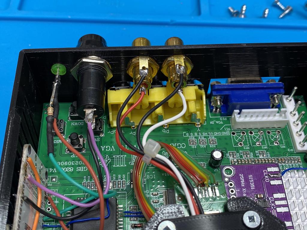
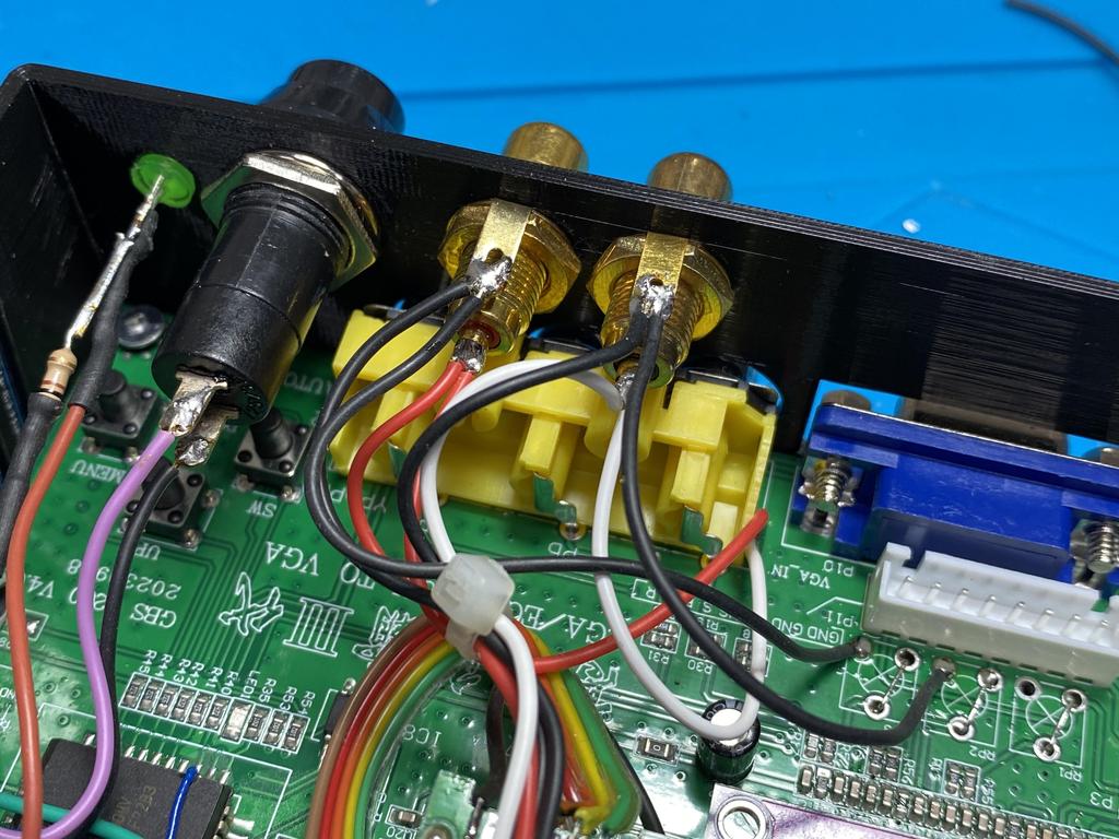
Here you can see the two audio input jacks with ground wires (black) and signal wires (red and white) that are soldered to the HDMI output board. The goal is to splice the signals from pins 12 and 15 to these:
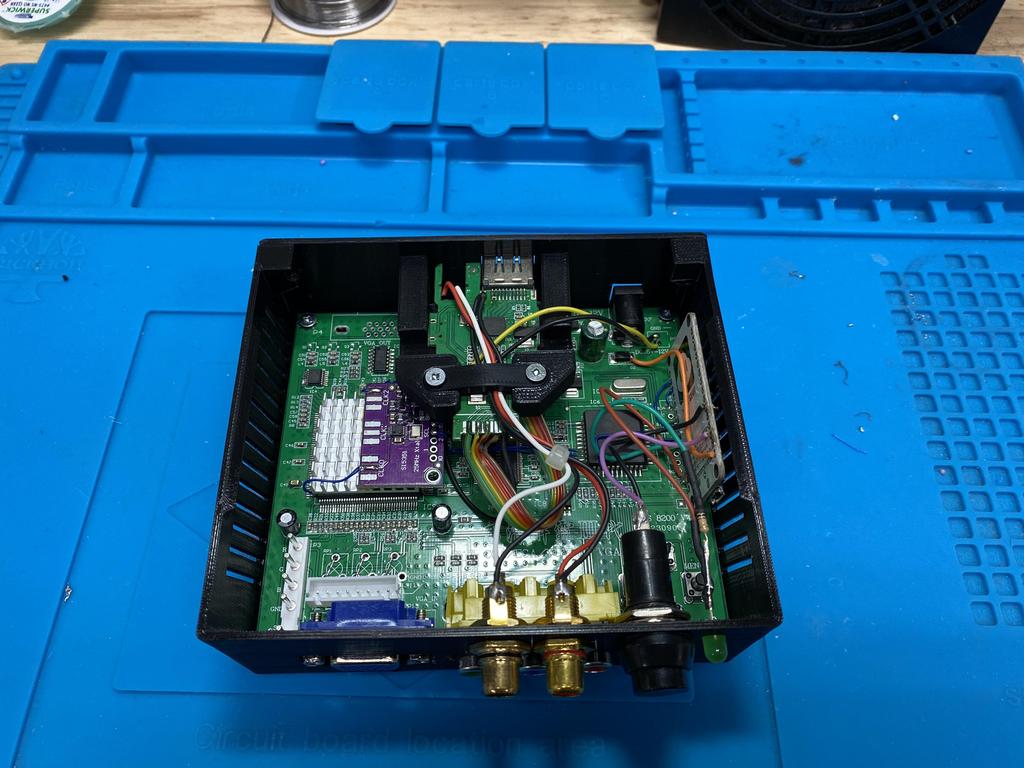
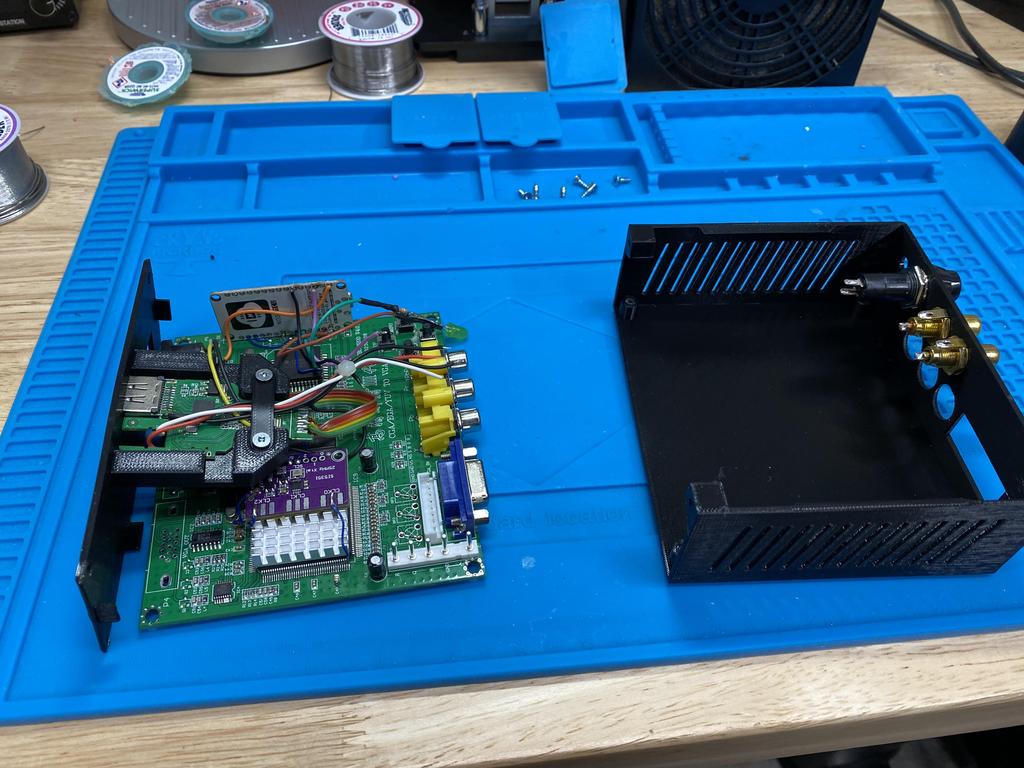
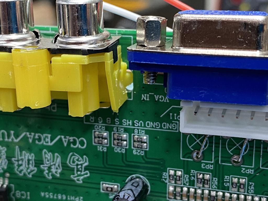
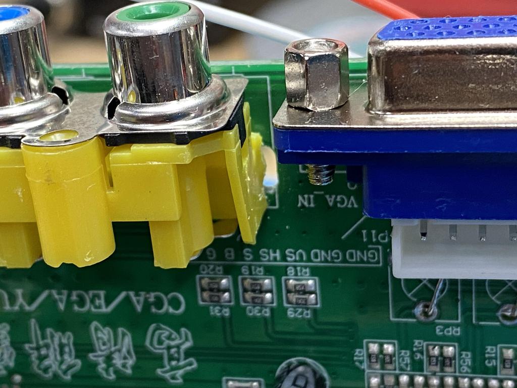
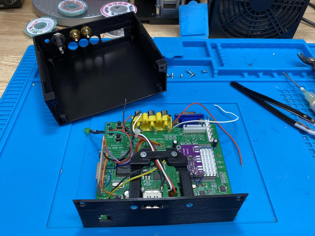
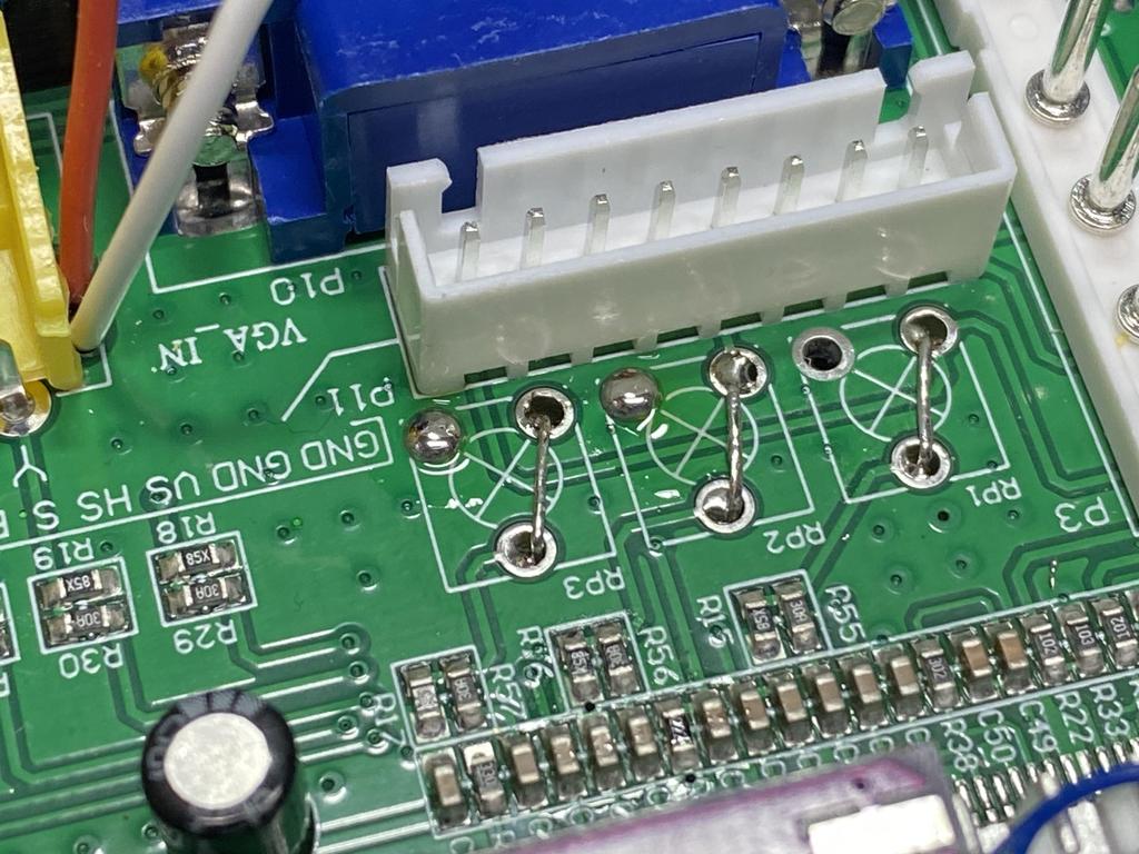
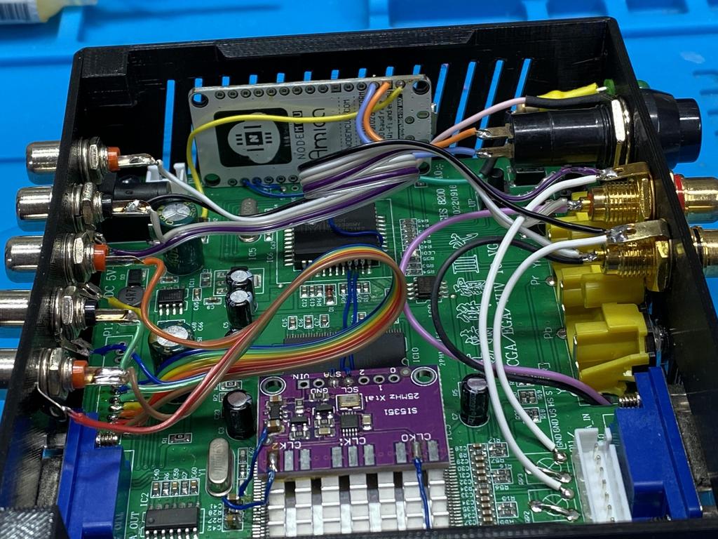
I took everything apart to be able to gain access to the underside of the GBS board, as there’s no other way to access pins 12 and 15:
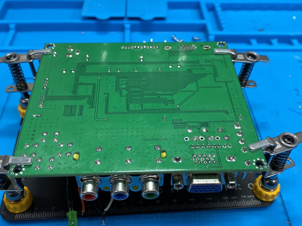
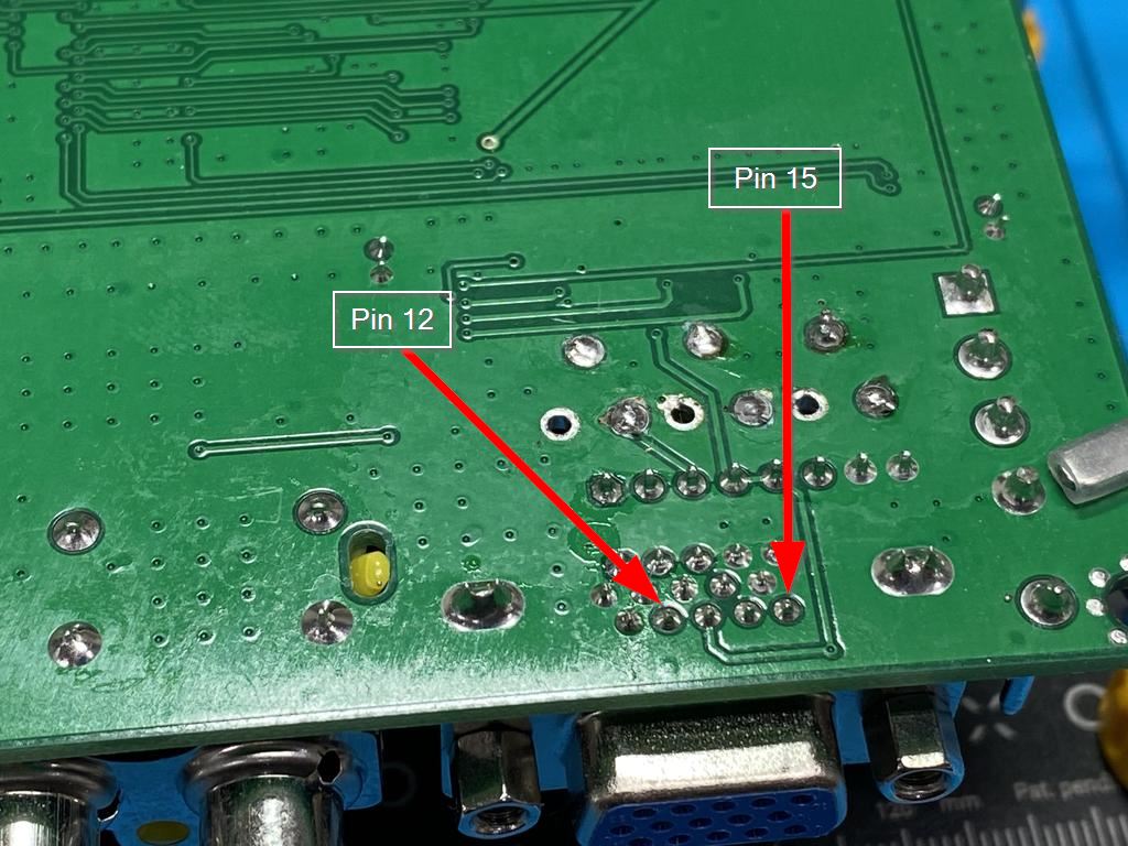
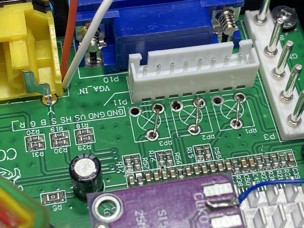
This is the area we need to work in. Before doing anything, I made sure that both pins 12 and 15 are actually not connected to anything, including ground. Luckily they weren’t, as it’s not always possible to isolate pins like this:
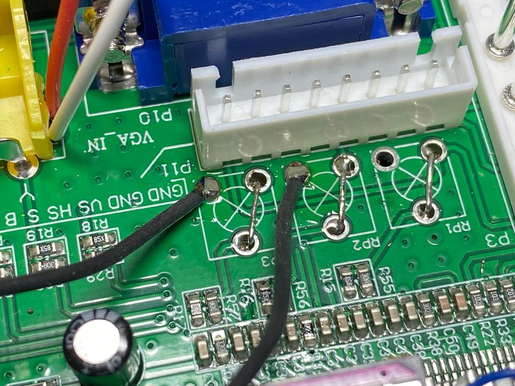
I soldered two wires to the pins:
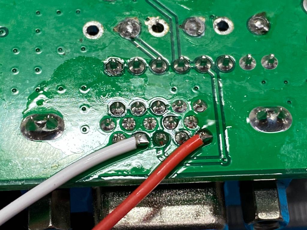
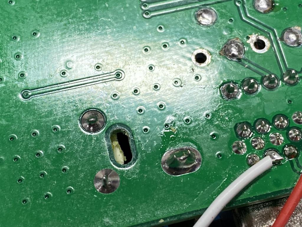
I decided to pass the wires through this hole nearby, where part of the plastic shell around the component input jacks is held:
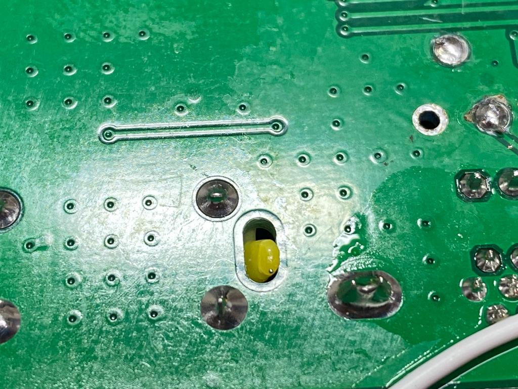
The hole was a bit small, so I decided to snip off a bit of the plastic. This doesn’t really affect the strength of the connector, as it’s held down quite strongly by several soldered pins:
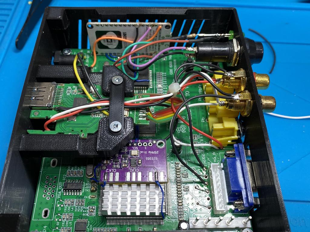
With the wires passed through, I flipped the board:
Next, I needed some ground wires for the audio signal. The DB15 input connection has ground on both pins 5 and 10, and since these are simply connected to the ground plane of the GBS board, I could tap any ground connection on the board. I decided to use these two vias where the original RGB pots used to be:
All four wires were now soldered and ready to be hooked up:
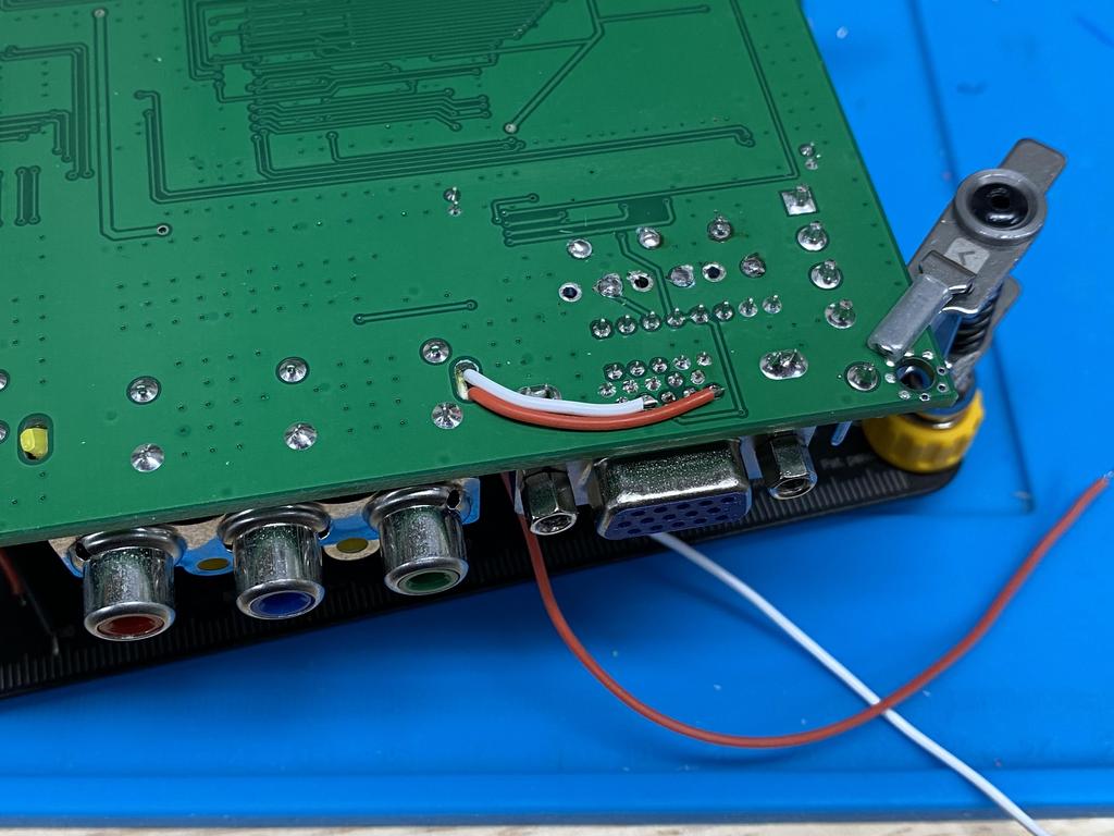
I spliced in the left (white) and right (red) signal wires together:
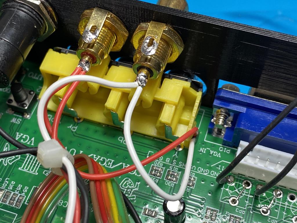
And then the ground wires:
Here’s a side shot:
And with that, I was done!
Testing #
I gave it a test, and it worked perfectly:
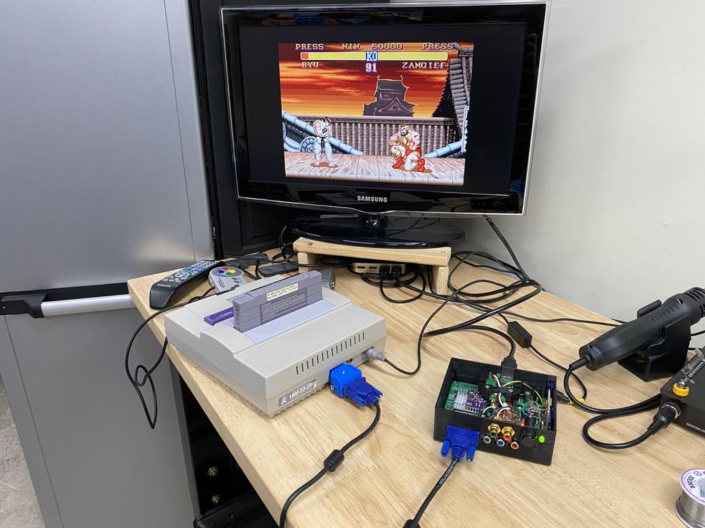
Of course, you can’t hear it working in the screenshots above, so I uploaded this video to demonstrate:
I then did pretty much the same thing on my other gbs-control, the one with YPbPr outputs:
Here they are, back in their place:
Thoughts #
I’m super happy with this mod! Since the GBS board leaves pin 12 and 15 disconnected, it’s easy to tap into them and take advantage of this cool feature of Jeff Chen’s VGA dongles. In his documentation, Jeff warns that the audio signal may be affected sometimes depending on the video signal passing through, but so far I haven’t noticed buzzing or anything.
It’s really convenient to be able to connect a single VGA cable from my consoles to the scalers. Now I just need to VGA-ify the rest of my consoles!