N64 RGB Mod and Custom Cable
In this post, I’ll go over how I RGB-modded my N64, and how I built a custom cable to connect it to my gbs-control.
RGB Mod #
For the RGB mod, following this excellent guide on retrorgb.com, I confirmed that my N64 was an earlier revision with a VDC-NUS video chip, which meant that I could install a “basic” RGB mod.
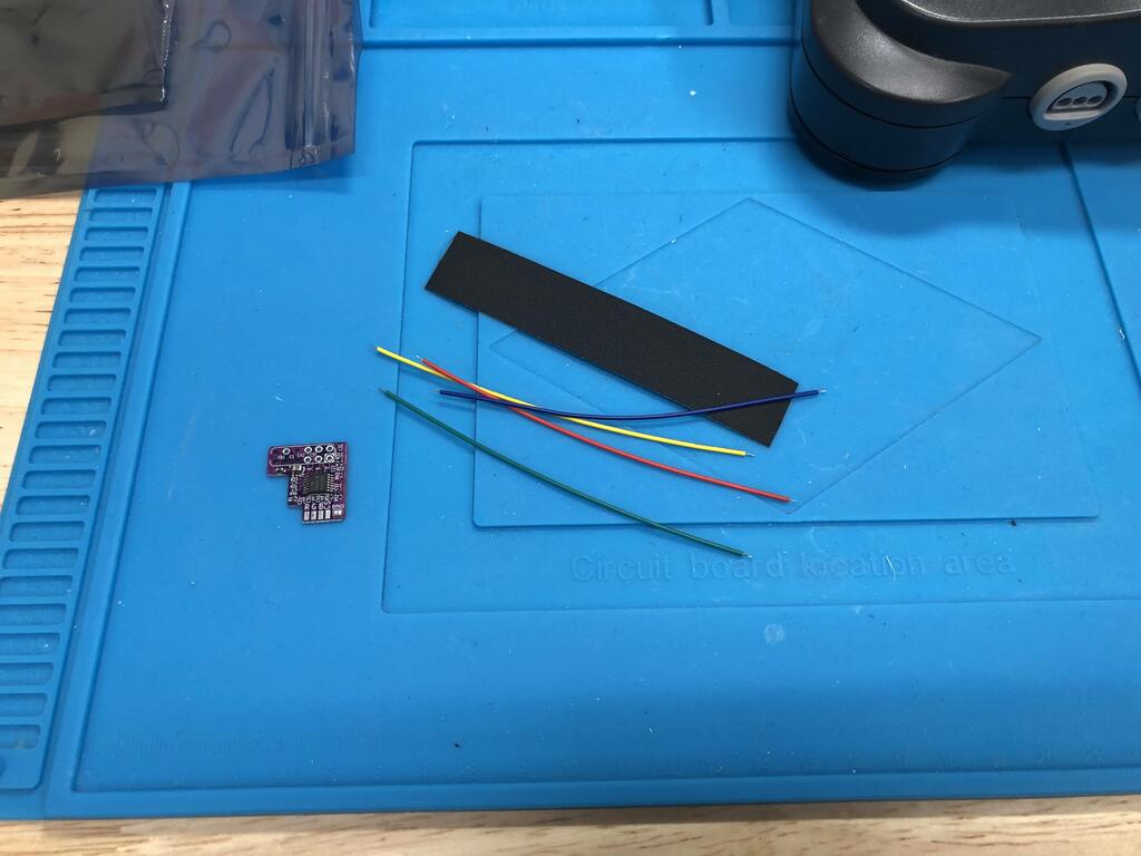
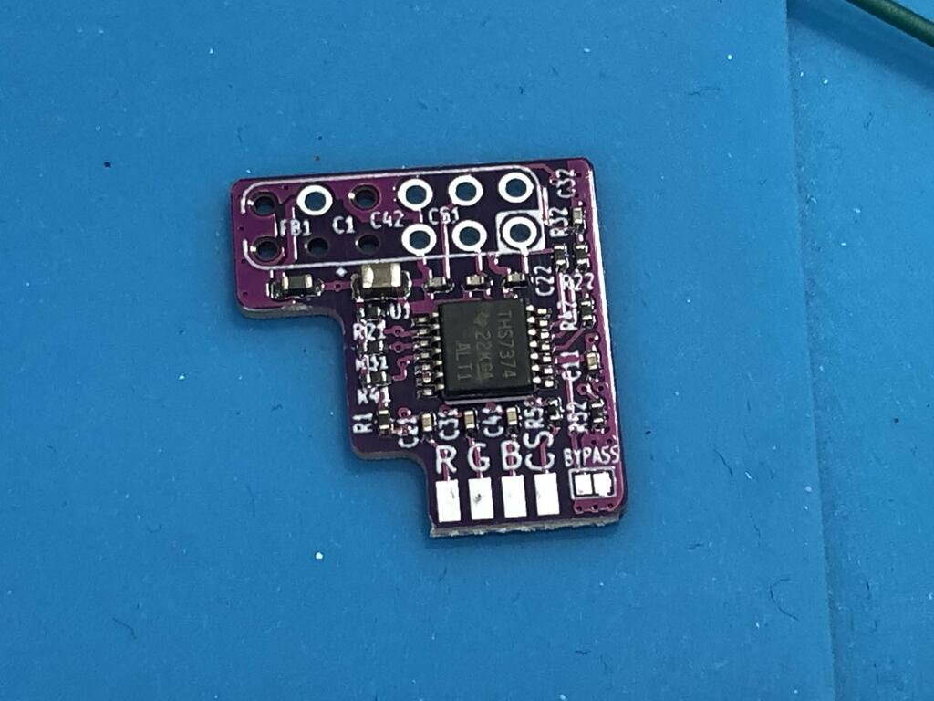
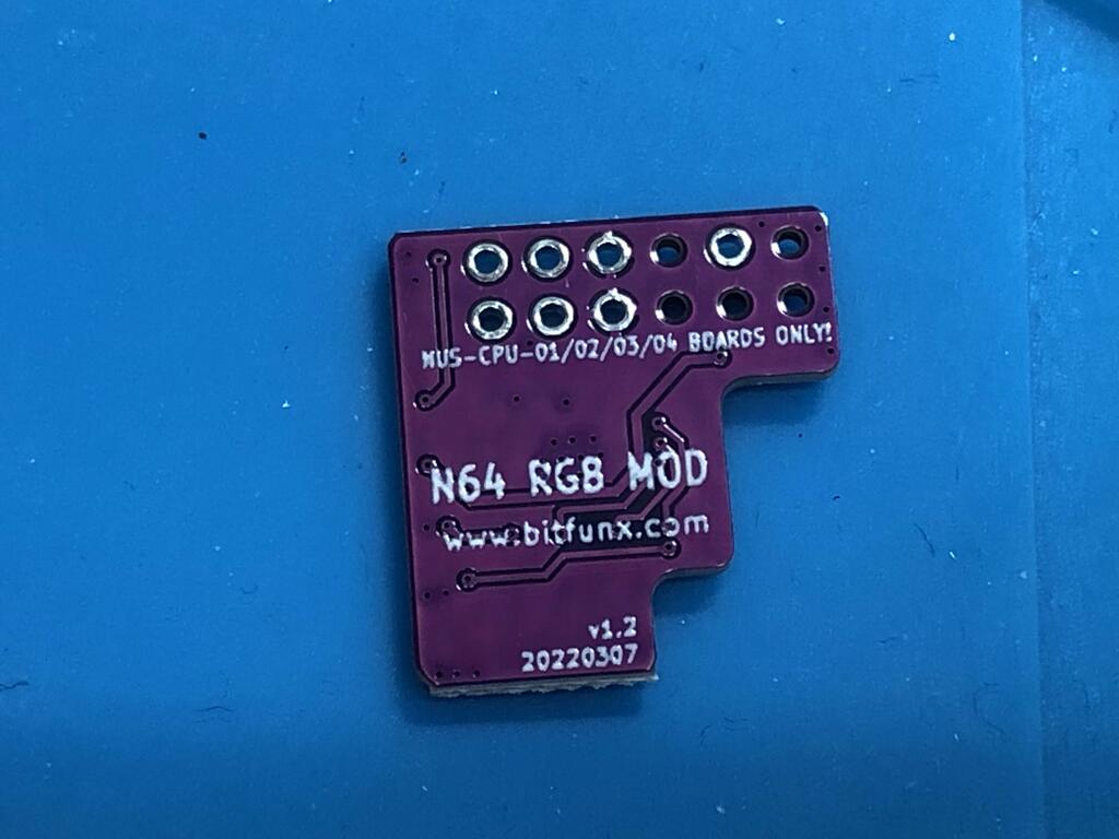
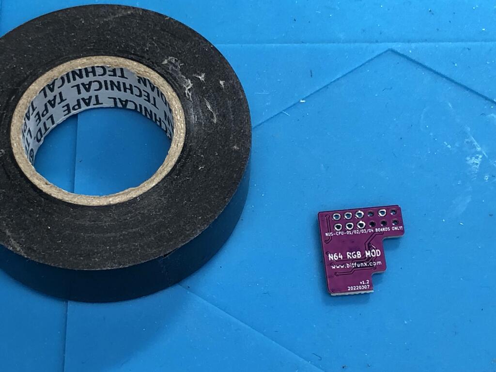
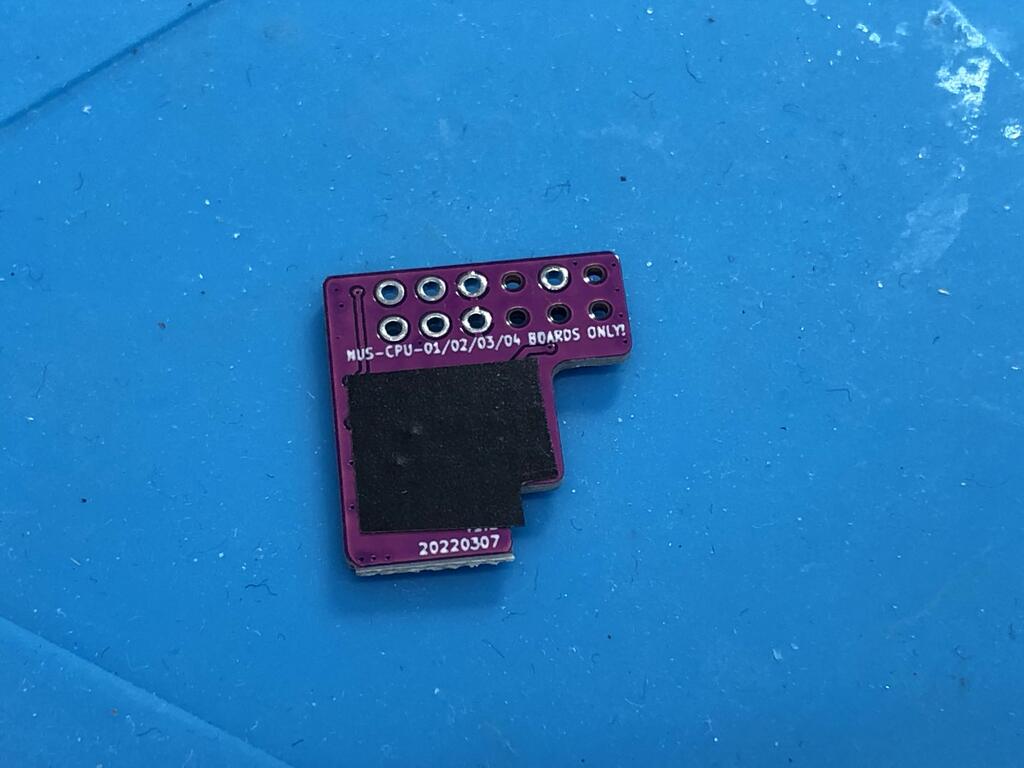
Initially, I tried to buy Voultar’s kit, but shipping outside the US was not available. So I decided to order it from AliExpress. Search for “N64 RGB Mod”, and you should get a few hits. The one I ordered is based off the bitfunx.com version. I received it a few weeks later:
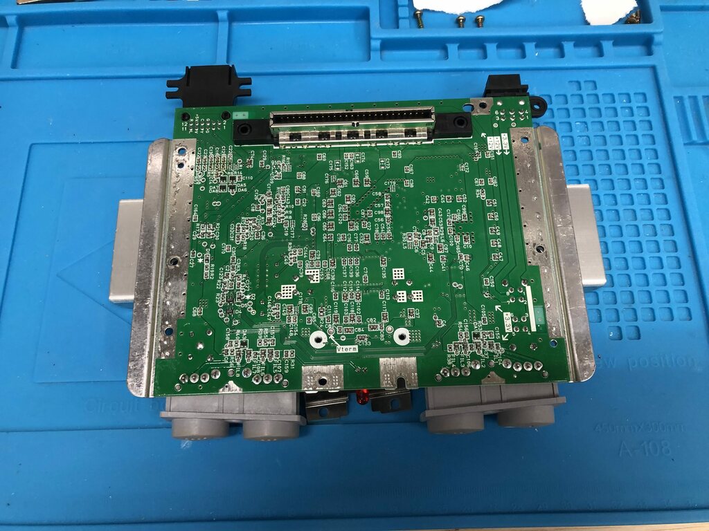
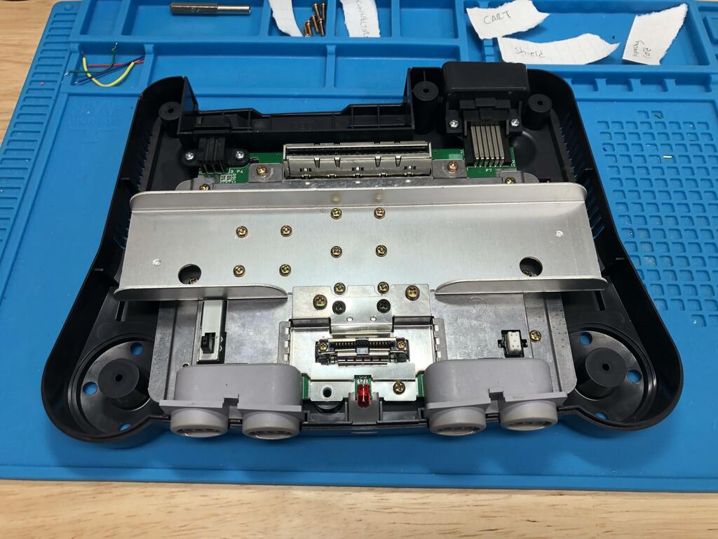
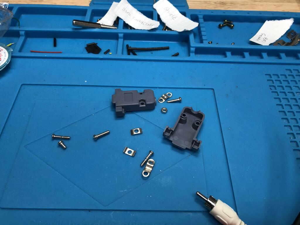
I opened up my N64 and got the PCB out:
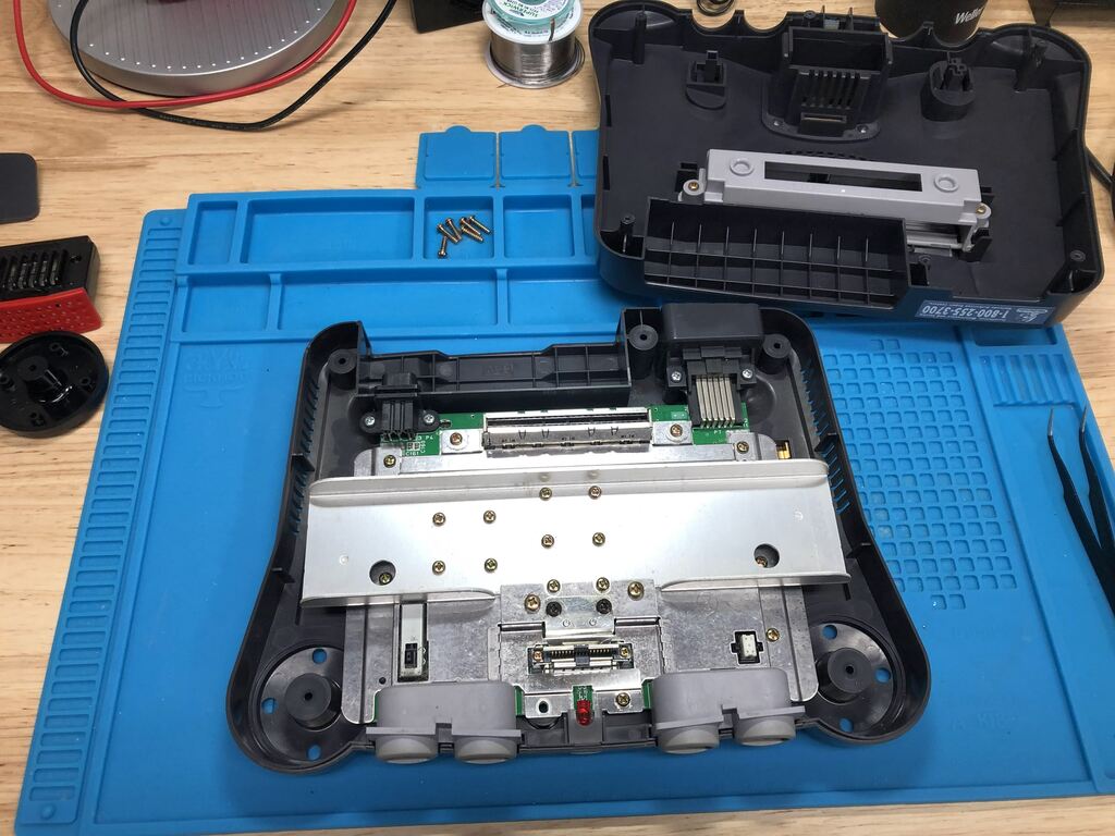
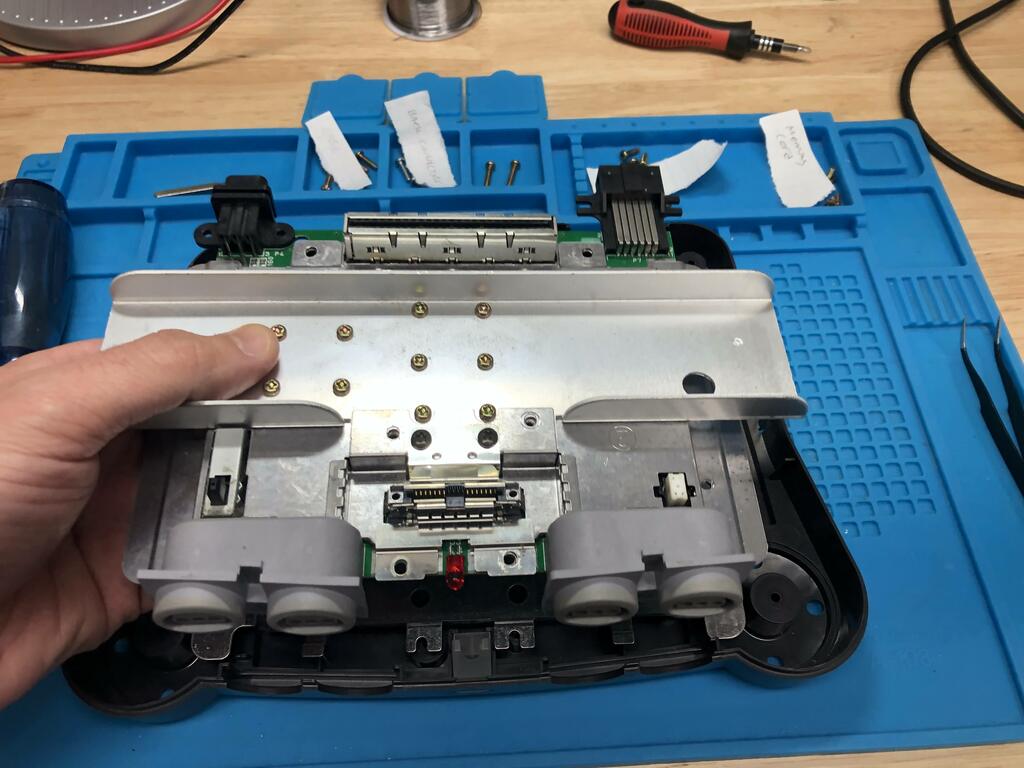
There are a good number of different sized screws, so I highly recommend keeping track of each set on a drawing so that it’s easy to put back together. Also note that you don’t need to remove the heat shield for this mod.
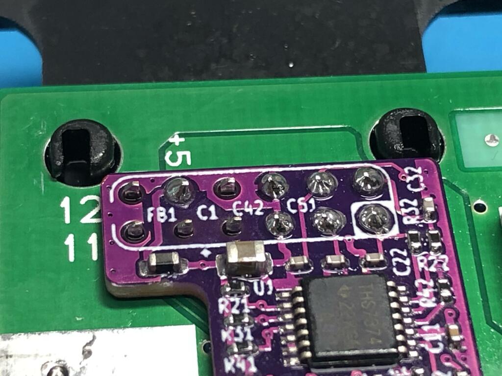
With the PCB out, I could now install the mod board over the multiout pins beneath the board (top-left):
As per the instructions, I added some wire tape to cover up a portion of the bottom, to ensure no shorts:
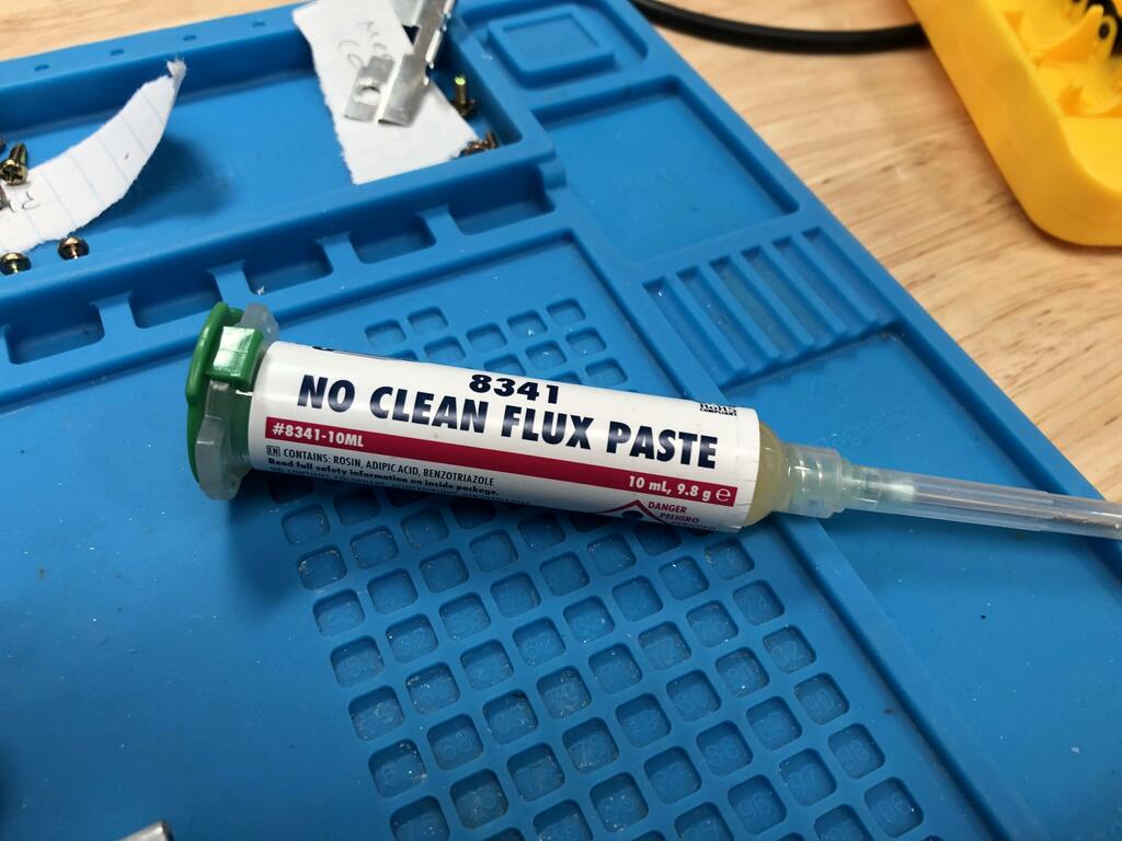
Then I placed it over the multiout pins and soldered it in place, using flux to ensure a solid connection:
This is what it looked like after cleaning up with some IPA:
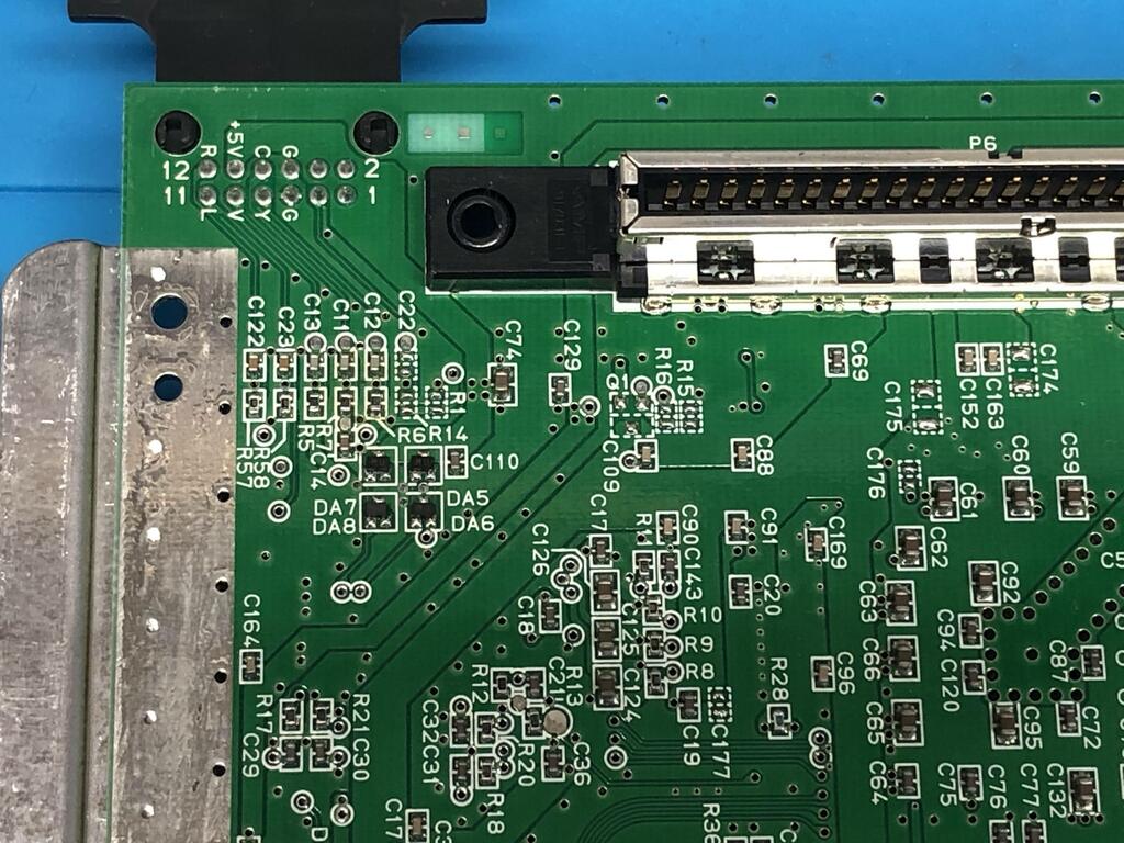
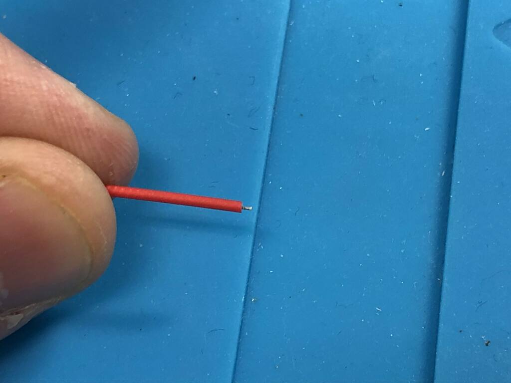
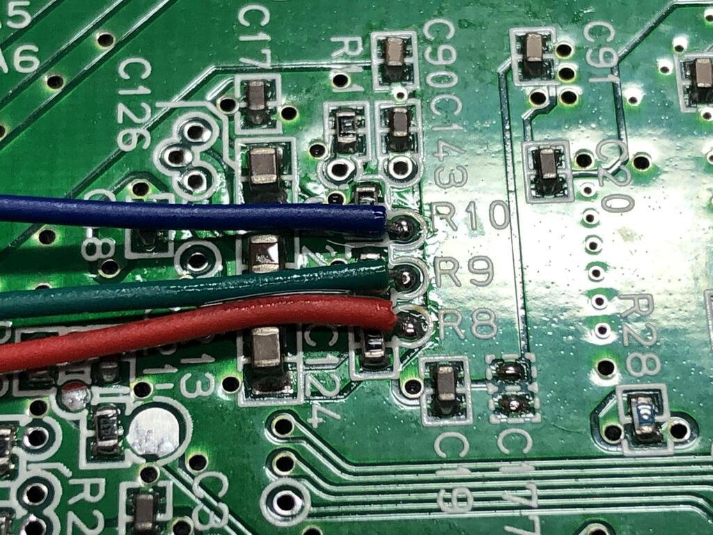
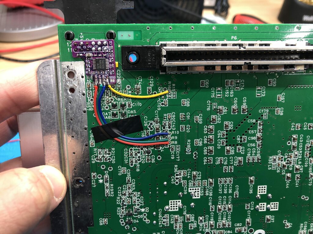
Next up was to solder the three wires to the red, green, and blue sources on the N64 PCB at the vias labelled R8, R9, and R10 respectively. The kit comes with the three wires, conveniently colored red, green, and blue. It’s really important not to insert the wires too far into the vias, otherwise they will make contact with one of the legs of the IC on the other side, and the mod will not work. I cut the ends of the wire very short:
I used a fiberglass pen to remove any solder mask and residue off the three vias, added flux, and soldered the three wires in place:
Next, I added a wire for clean CSYNC to the via labelled R16:
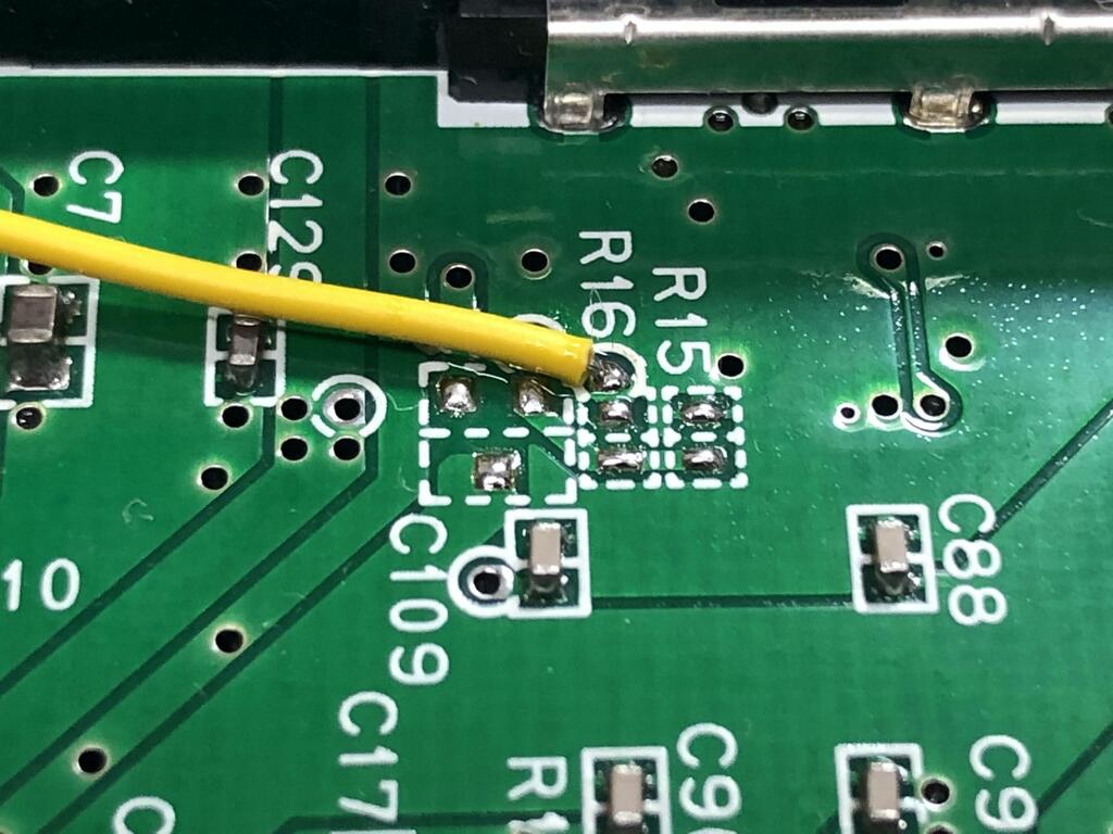
Note that my revision of the N64 motherboard did not have CSYNC connected to the multiout’s pin 3, so I did not have to do any more than this. I knew this because C22, R1, and R14 were all unpopulated:
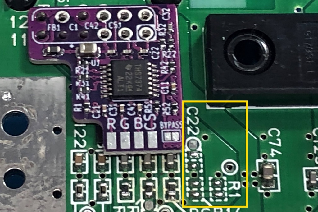
If the cap and two resistors are there, you can simply remove them.
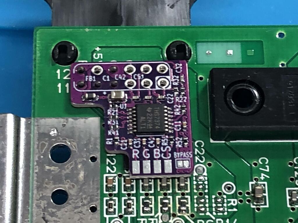
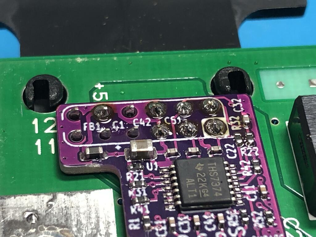
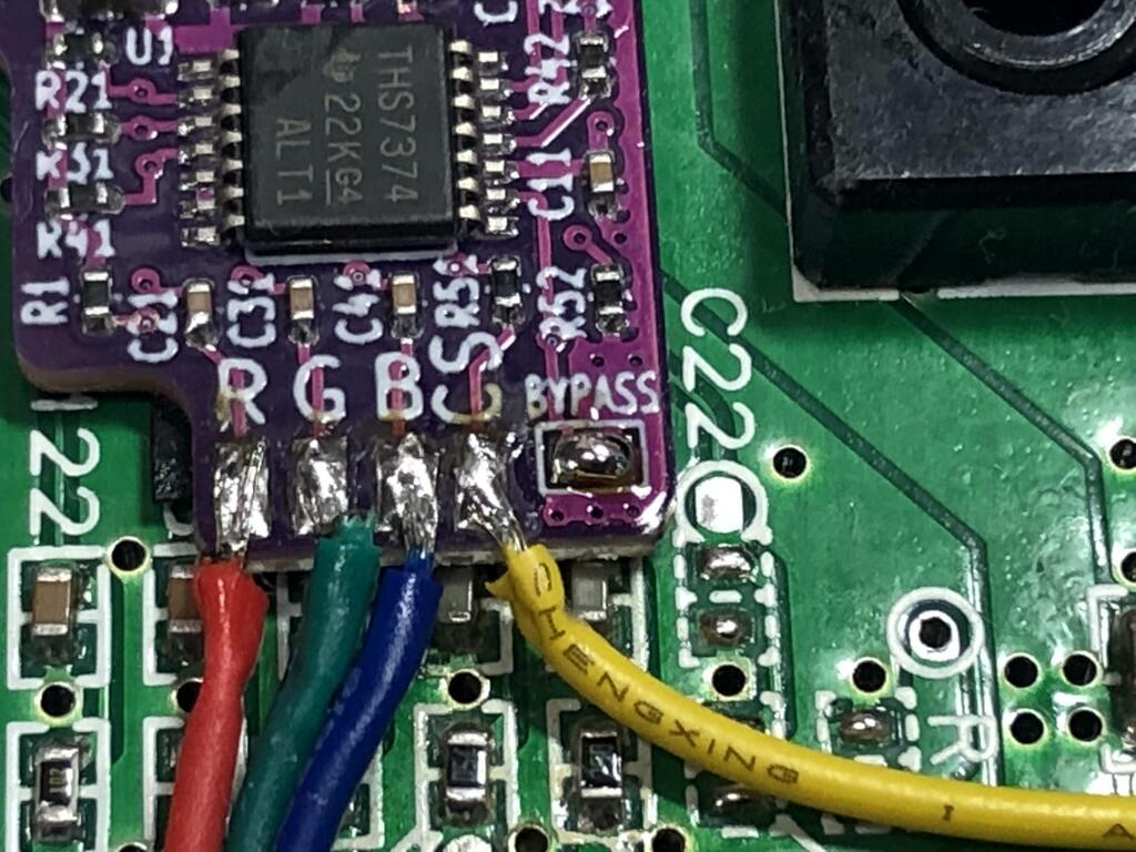
Finally, I cut the 4 wires to length and soldered them to their respective pads on the mod board:
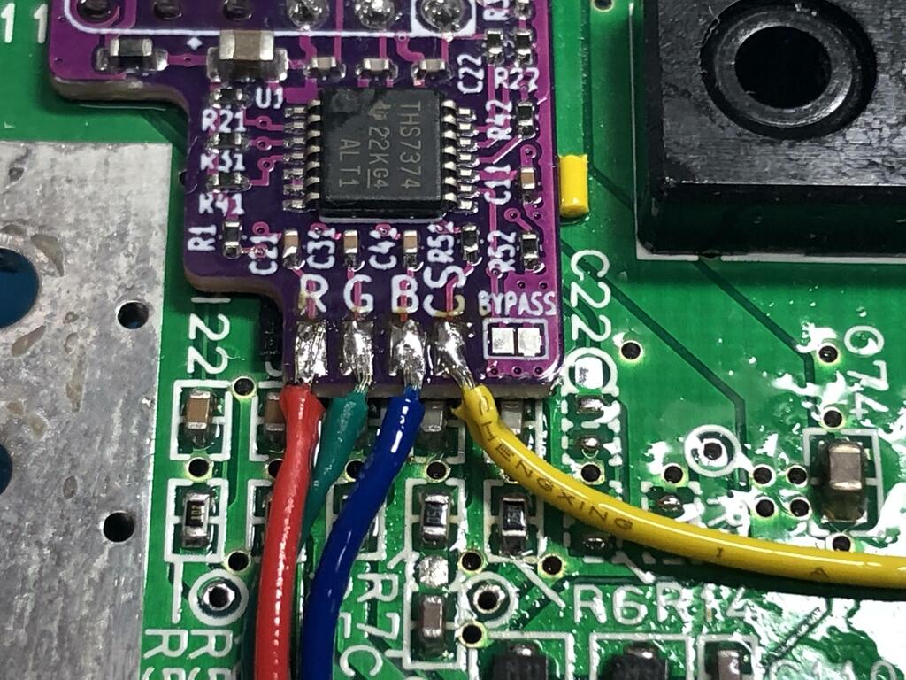
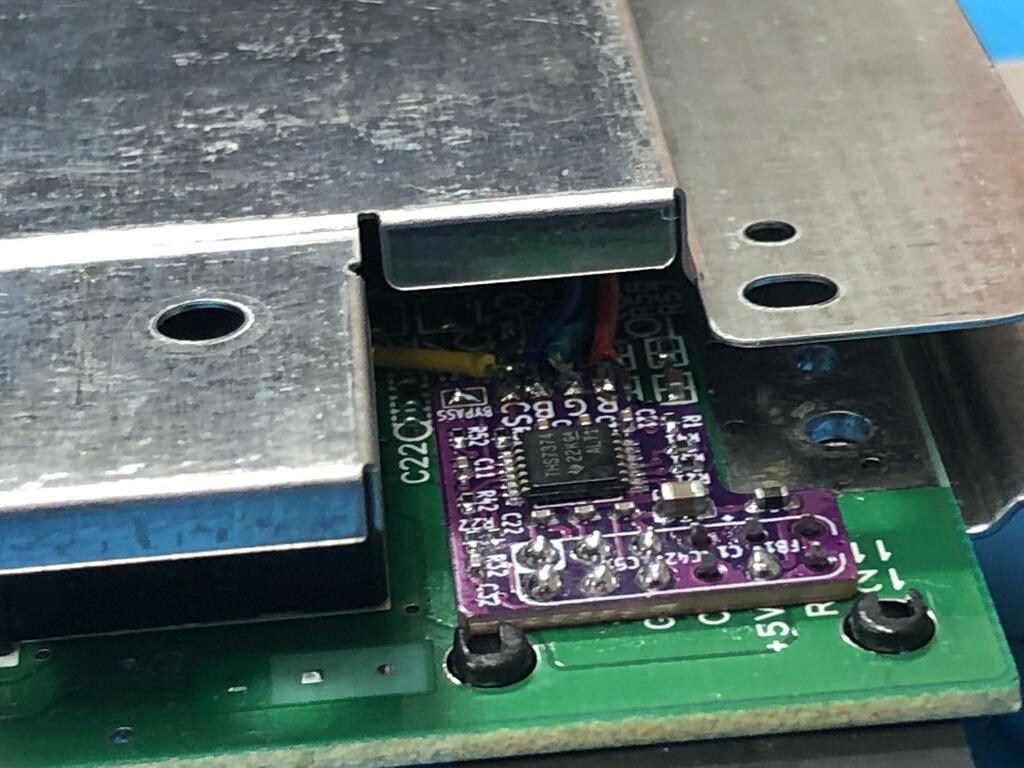
Although this came later while testing, I’ll mention it here: the mod board uses a THS7374 IC as a video amplifier, and has an option to bypass this IC’s built-in filtering by soldering two pads together. After testing both, I decided that I preferred the look without the filtering, and soldered the two pads under the BYPASS label:
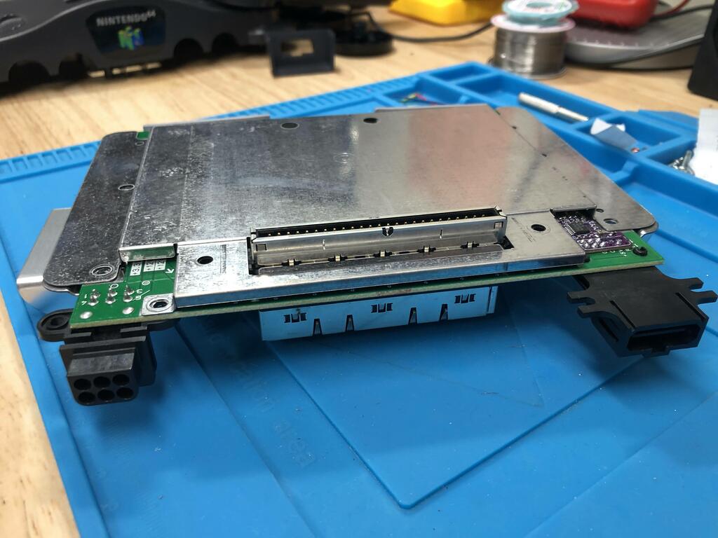
With the mod in place, it was time to close up the console. However, the metal shielding now comes into contact with the new mod board, making it difficult to close, and possibly resulting in shorts:
So I used some pliers to fold in this flap in:
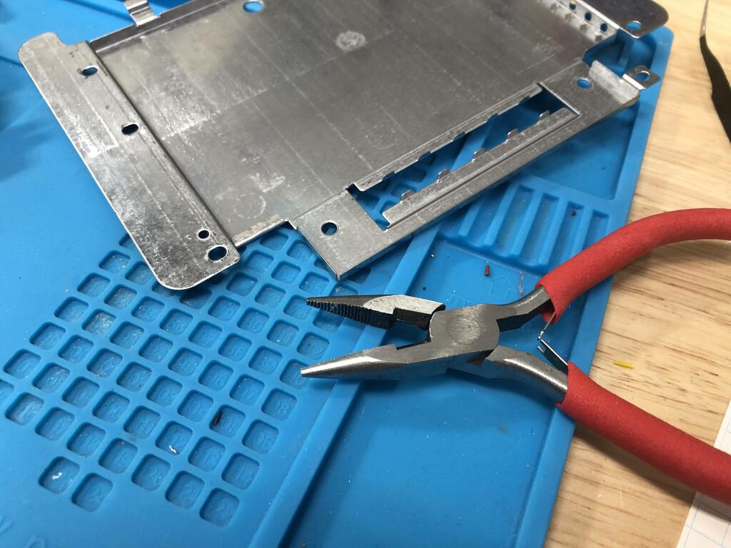
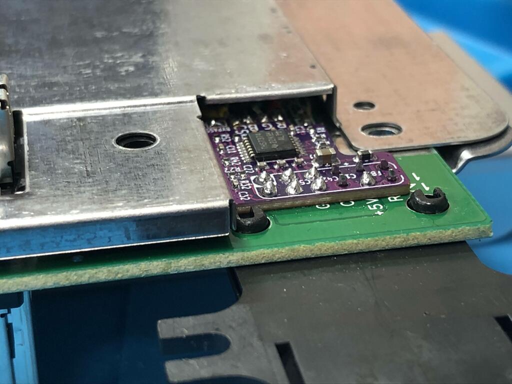
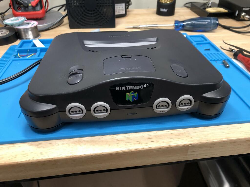
Now I could finally close up the console:
Custom RGB to 15 Khz “VGA” cable #
With the RGB mod complete, I now needed a way to connect my N64 to my TV to actually play in RGB mode. The most common way people do this is by purchasing an HD Retrovision SNES YPbPr cable. This cable will work with the N64 mod, but it’s quite expensive and usually on backorder, taking months to arrive.
Since I knew I had a gbs-control, I decided to make my own cable, like I did for my PS1. One of the challenges would be to output not only video, but also audio. Further, I had read that the RGB signals would need 220uF capacitors on each line to properly attenuate the signals. In searching for cable options, I stumbled upon this one by retro-access.com and used it as inspiration.
Design #
Here’s a table of the final design for how I wired everything up (see pinouts for each below):
| SNES Signal | SNES Pin | VGA Pin | VGA Signal | RCA Audio | Cable Color |
|---|---|---|---|---|---|
| Red | 1 | 1 | Red | Red | |
| Green | 2 | 2 | Green | Green | |
| Blue | 4 | 3 | Blue | Blue | |
| GND | 5 | 10 | GND | Black | |
| SVID-Y | 7 | 13 | HSYNC | Yellow | |
| Right Audio | 11 | Red | Orange | ||
| Left Audio | 12 | White | White | ||
| GND | 6 | GND | Brown |
The Cable Color column is not really relevant to how to wire this up - I just assigned colors based on the cable I ordered from AliExpress. I left it here, though, to help to understand the pictures below.
One thing to note: in creating my cable, I went through a few different iterations of determining how to best connect sync from the SNES multiout to my GBS-control via VGA pin 13. I had three options: CSYNC (pin 3), composite video (pin 9), or S-video Y (pin 7). CSYNC is the pure sync signal from the N64 that I connected to the multiout as part of the RGB mod install. This is a TTL-level signal, which means that a 480 ohm resistor in series is required to attenuate the signal down to expected levels for most TVs and the gbs-control. The other two are video signals that also carry sync in them. After testing out each option, I found that using S-video Y worked best with my gbs-control, resulting in no sync loss, and no audio interference. I mention this, though, as it may not be the best solution for everyone.
Here’s the pinout for the N64 (and SNES) multiout connector for North American revisions from pinoutguide.com:
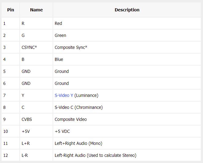
NOTE: CSYNC (pin 3) is replaced by +12V on PAL SNES and PAL Gamecube consoles (but not PAL N64), so it’s really important not to use this cable on those models.
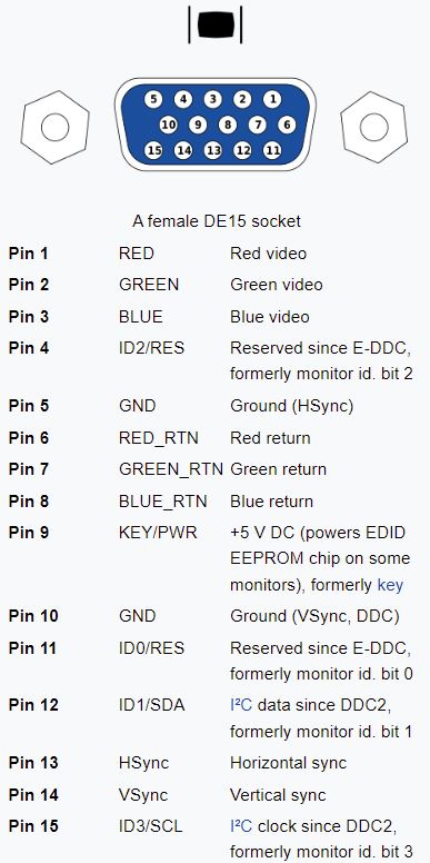
Here’s the pinout for a standard DE-15 VGA style connector from Wikipedia:
For the audio output, I decided to use a regular white + red RCA cable, as gbs-control uses this for audio input.
Creating the cable #
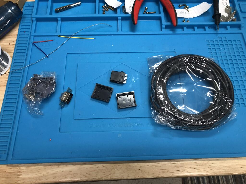
From AliExpress, I ordered the parts I would need:
- SNES male connector, $5.31 for 2
- DE-15 male VGA style connector, $3.70 for 2
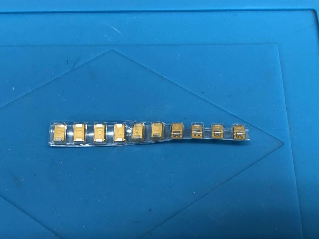
- D-size 10V 220uF tantalum capacitors, $4.61 for 10
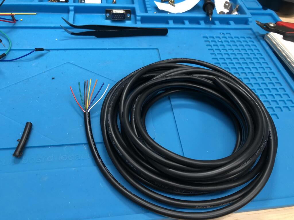
- 5 meters 8 core 28 AWG sheathed wire, $10.21
I received everything after a few weeks:
VGA + Audio End #
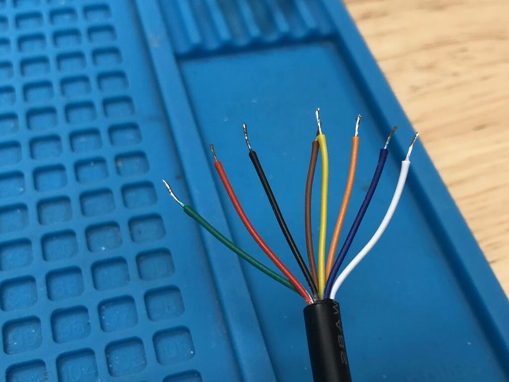
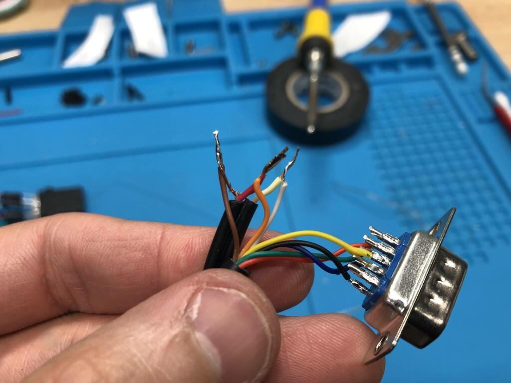
I stripped one end of my (way too long) cable, stripped each wire, and tinned them:
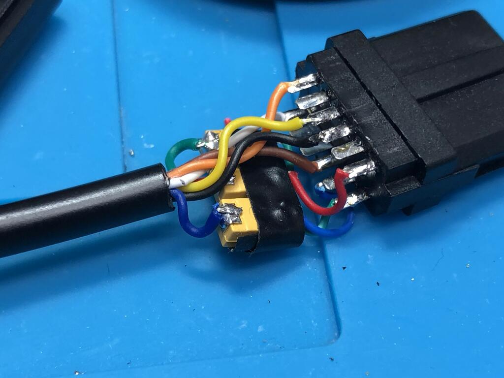
I soldered each wire for the video signal to the VGA connector, leaving the audio connectors aside:
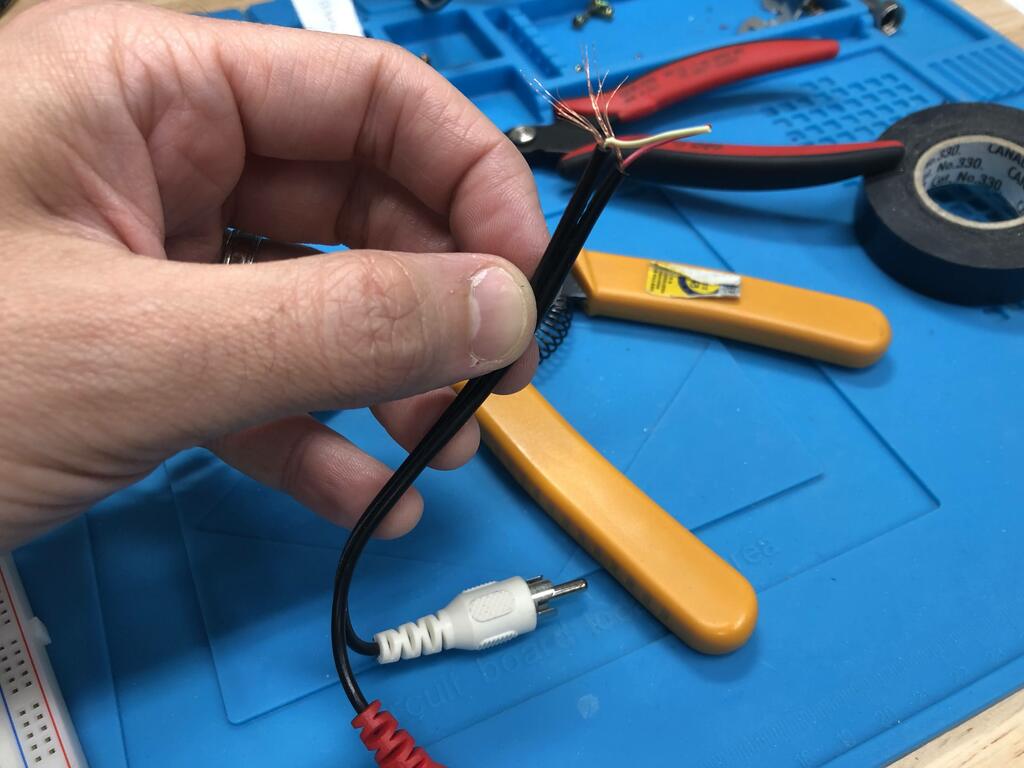
Using an old RCA audio cable, I cut it down to length, combined the grounding wires wrapped around each of red and white, and tinned all three:
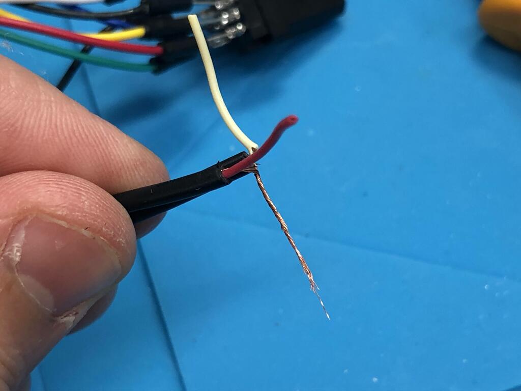
I soldered them to their respective wires on the cable, and covered up the exposed wires with heat shrink tubing:
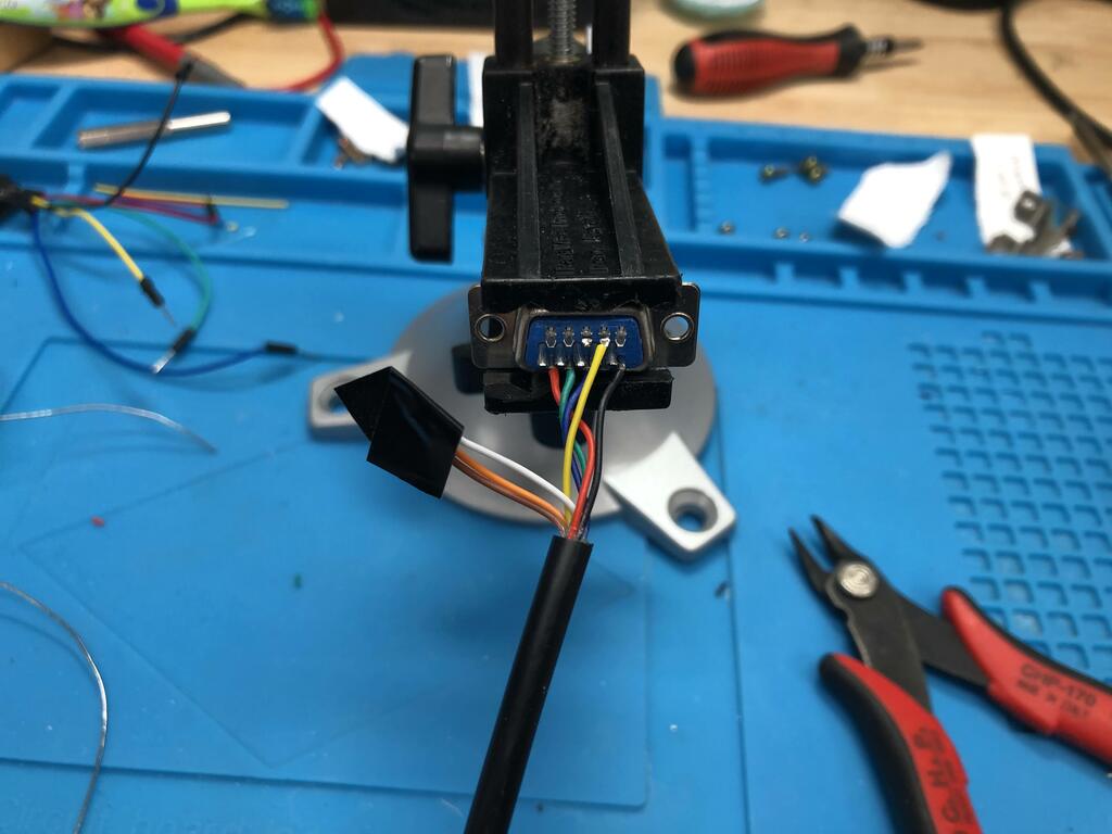
Finally, I put everything together into the VGA connector shell, clamping both the main cable along with the RCA cable together with the strain relief:
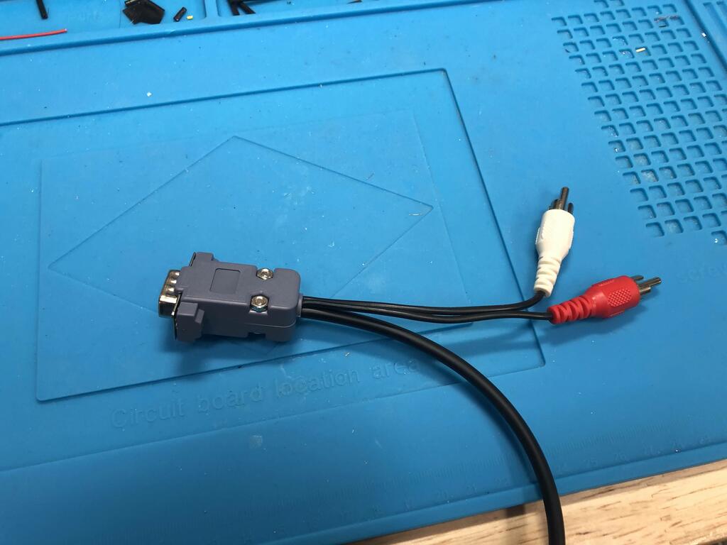
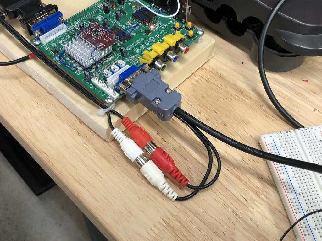
I must say that I’m quite happy with how this side ended up. Here’s what it looks like connected to the gbs-control:
Multiout End Attempt #1 #
For the SNES multiout end, initially, to test things out, I actually soldered Dupont cables so that I could test things with a breadboard, like capacitor values and resistors, and what sync source to use. Also, the tantalum caps took a little longer to receive than the rest of the parts, so this way I could at least use through-hole caps:
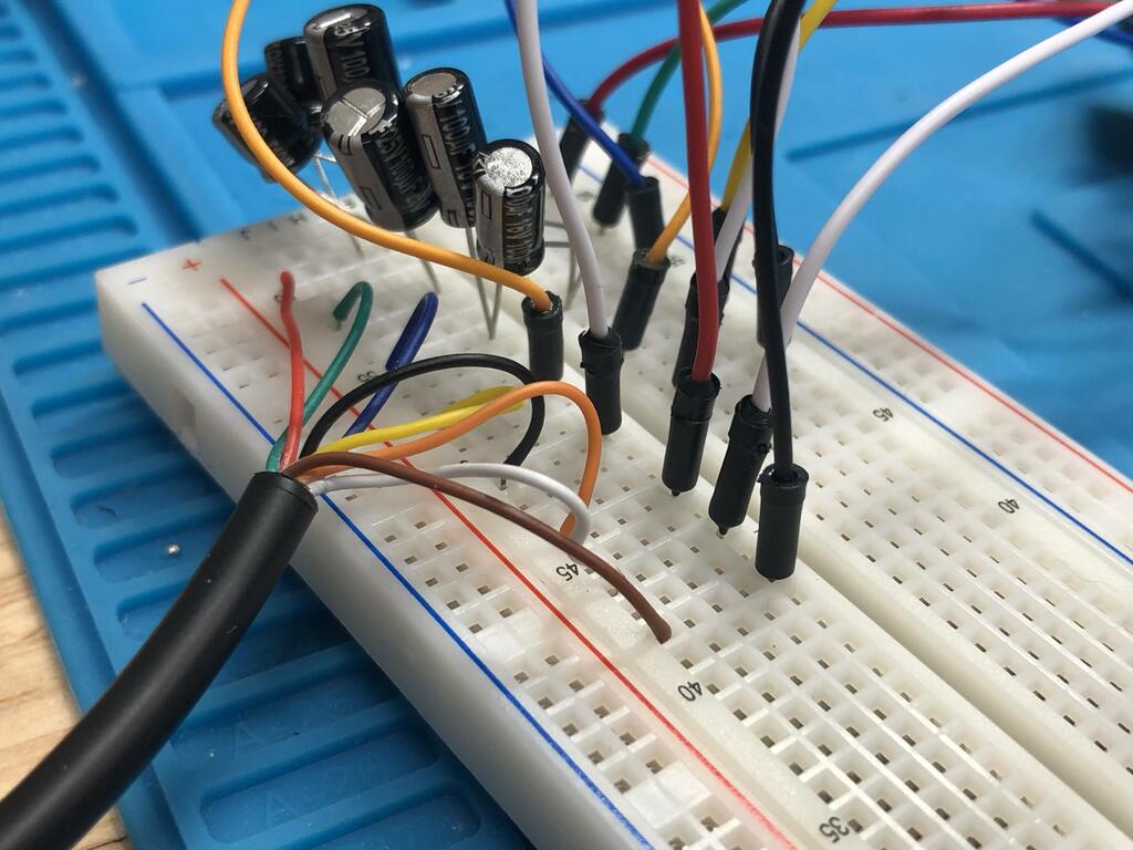
It may not be clear in the image above, but I actually had three pairs of 100uF capacitors in parallel to get close to the 220uF required for each color signal. With this in place, I was able to test the cable, and amazingly it worked first try!
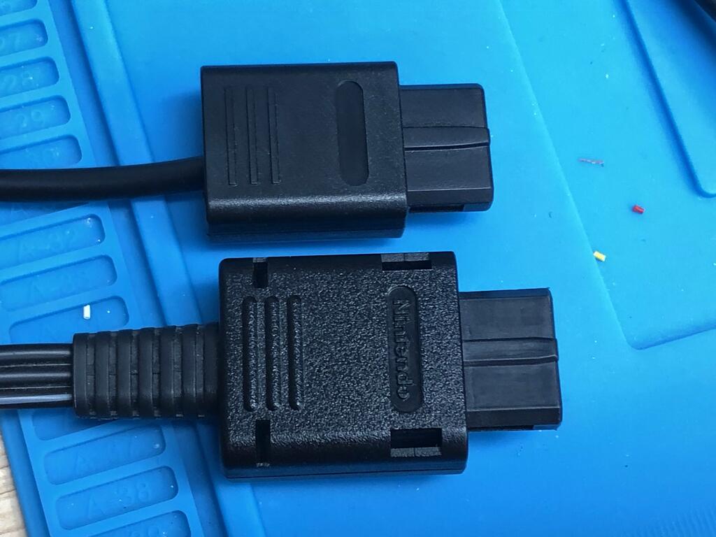
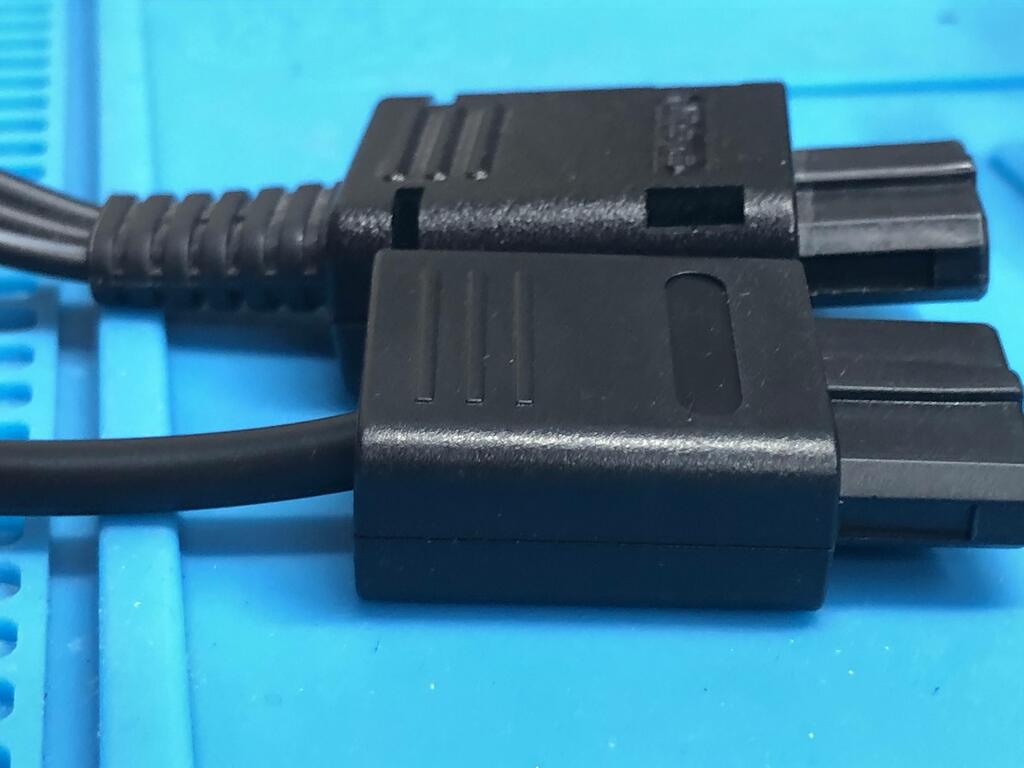
Once the tantalum caps came in, it was time to properly wire the multiout end. This part was much harder, and quite fiddly. The multiout shells available on AliExpress (and other sources as far as I can tell) are smaller than the original. For comparison, here’s the one I got from AliExpress (top) compared to the original N64 multiout cable (bottom):
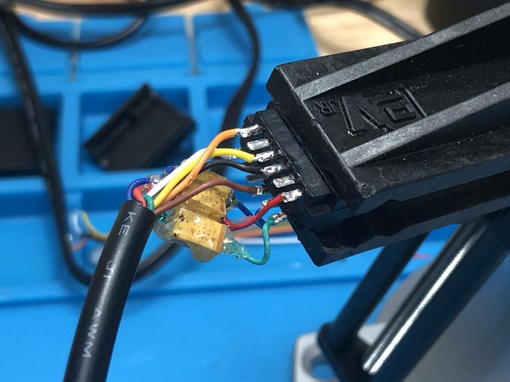
The real challenge was fitting the tantalum capacitors along with the rest of the wires in this small shell:
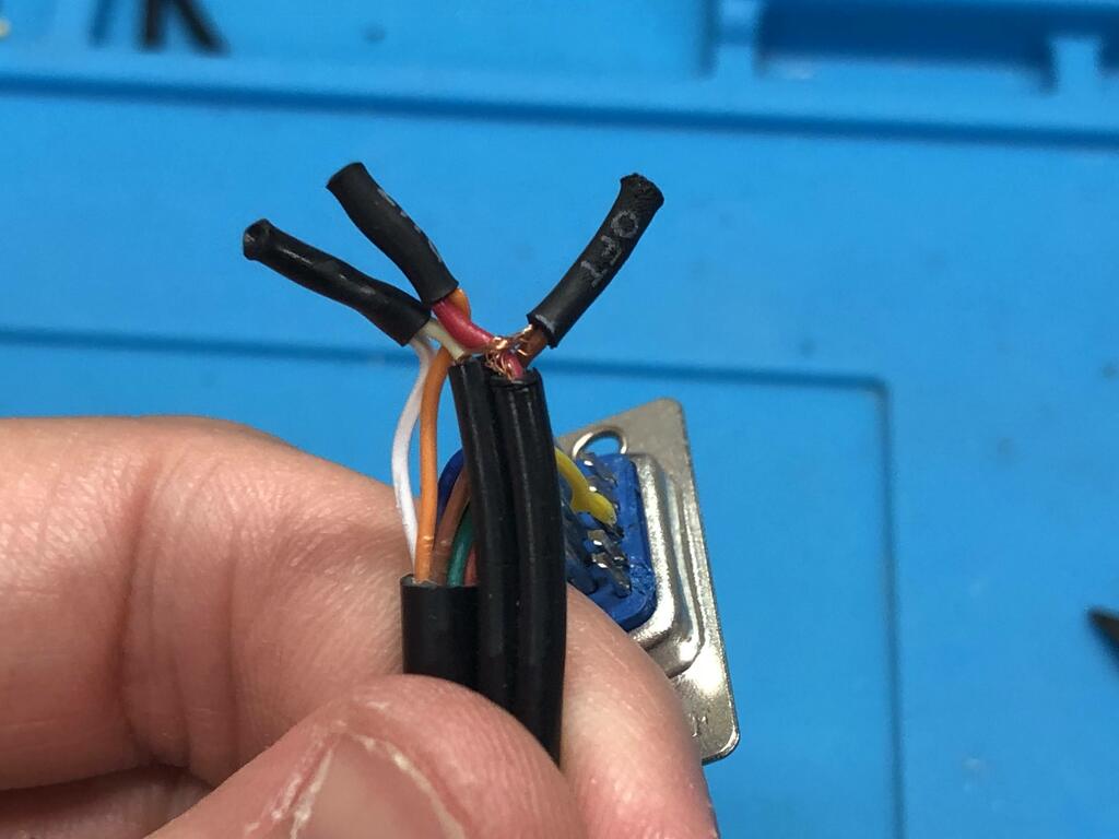
I tried many things, but I’ll only share a couple here. First, I shortened and soldered the RGB lines to the caps:
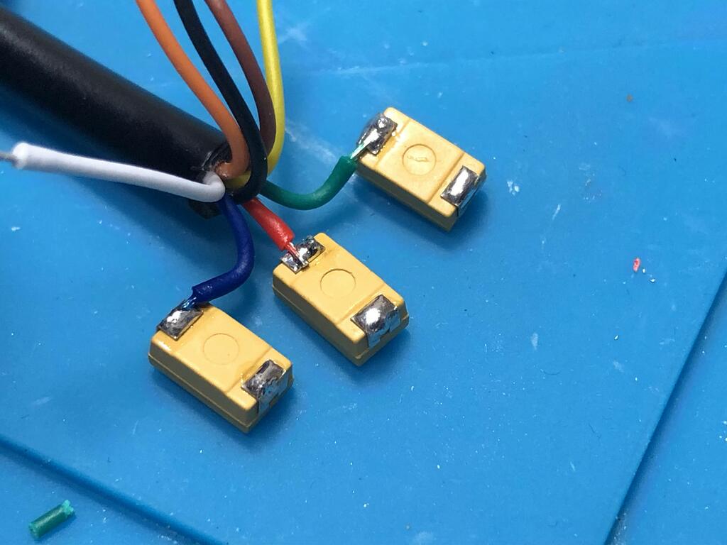
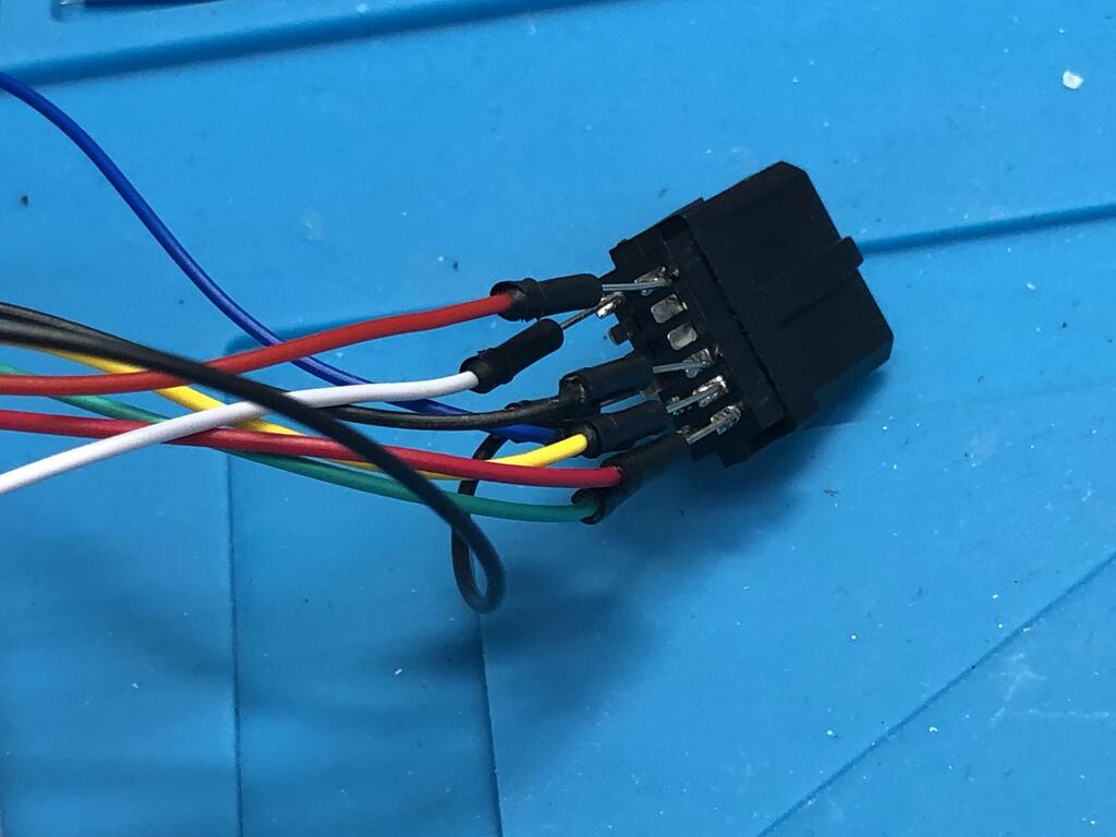
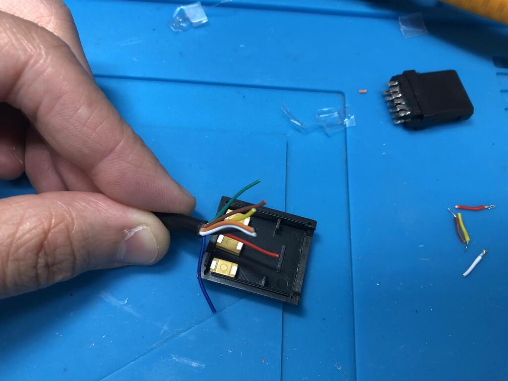
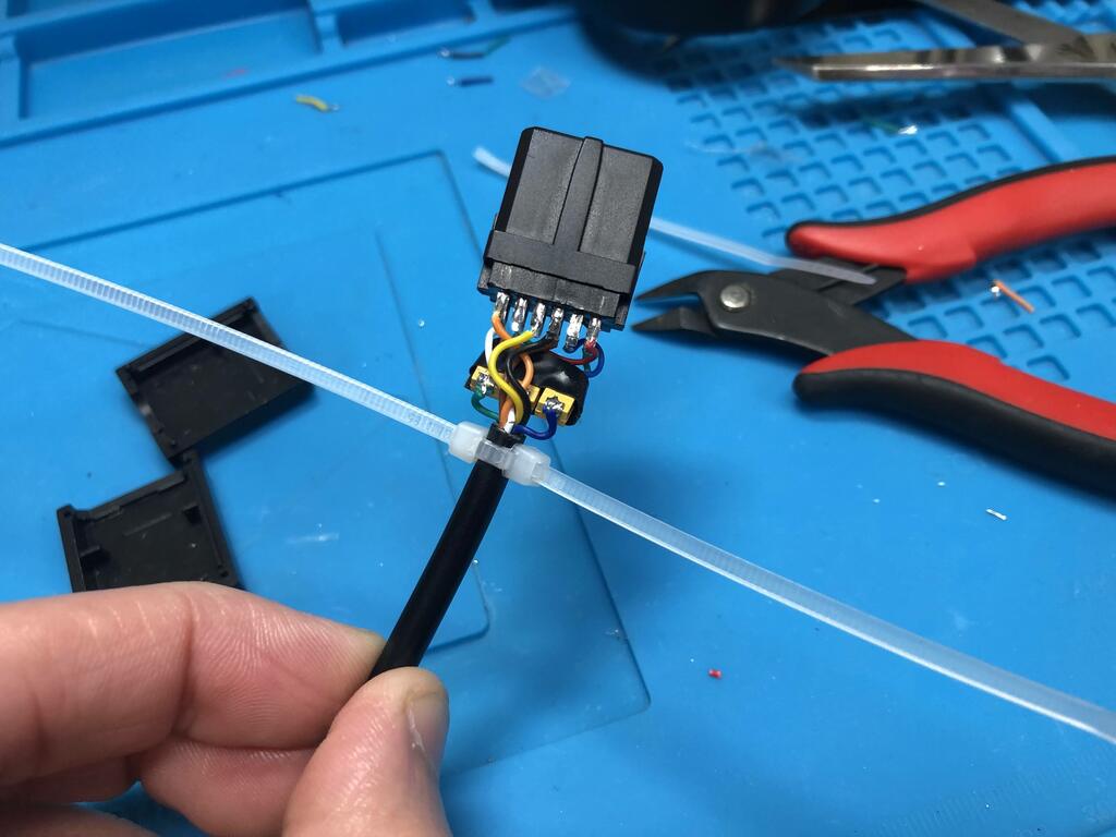
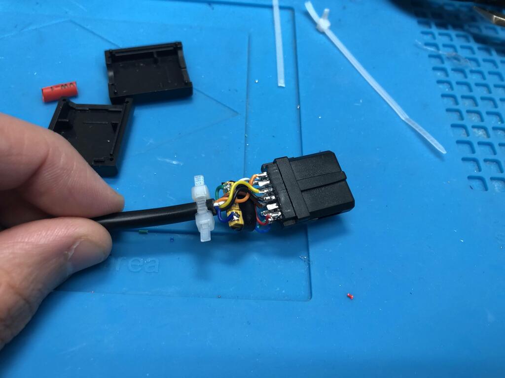
I soldered the rest of the wires to their respective pins on the multiout connector:
The red heat shrink tubing is something I initially put around the 3 tantalum caps, but eventually removed because I found it too difficult to manage. Instead, I wrapped the three caps in some wire tape to keep them together:
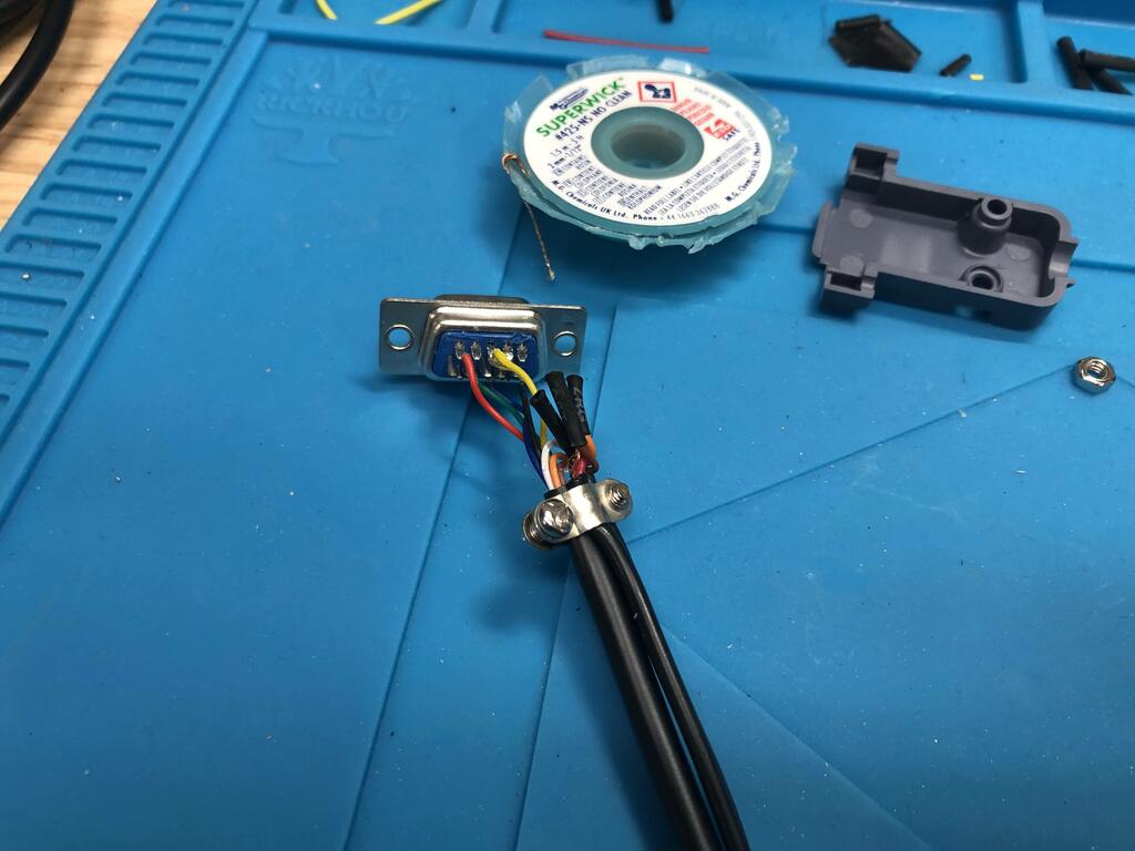
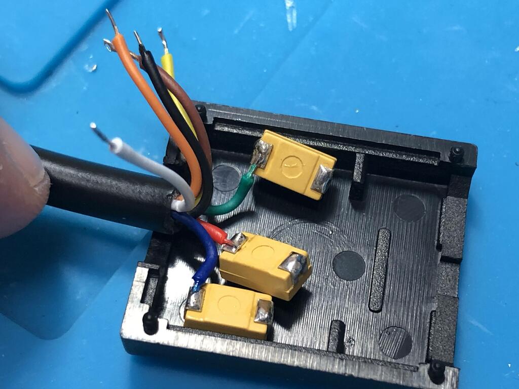
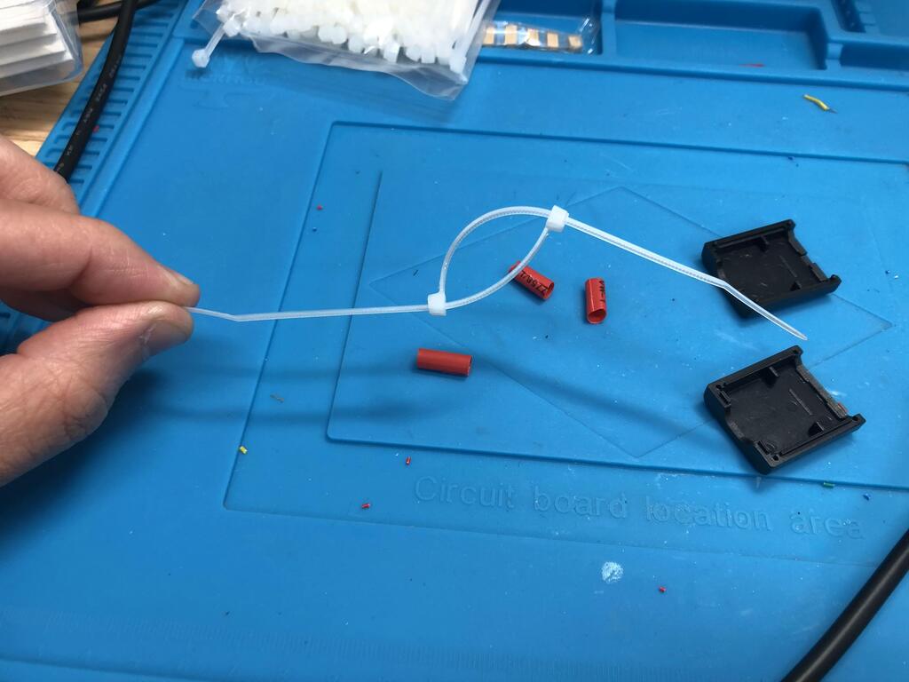
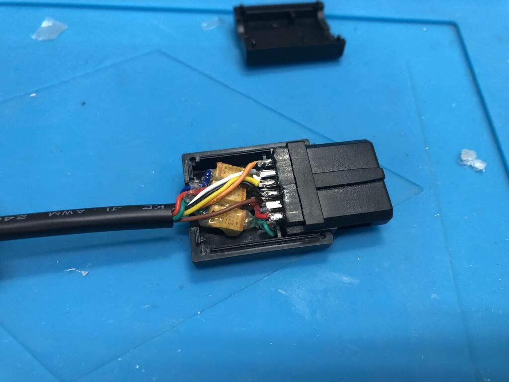
The multiout shell did not come with any kind of strain relief, so I made my own using two tie wraps threaded into each other:
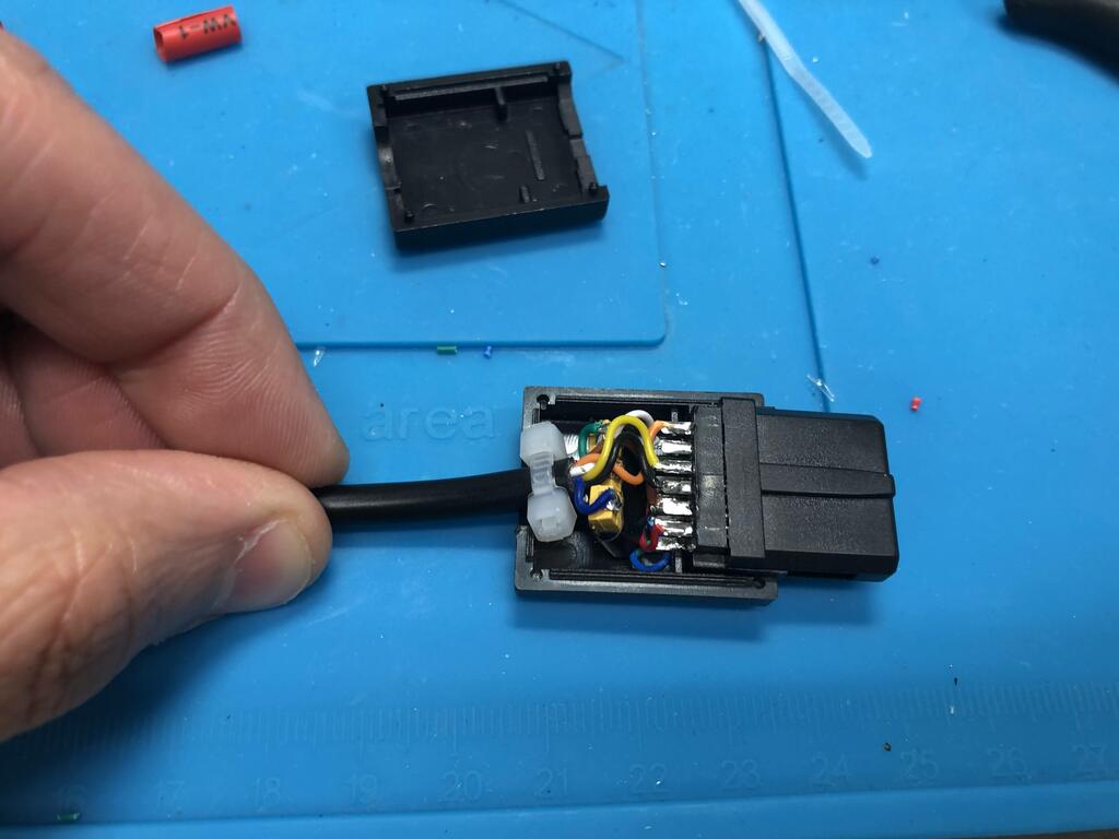
Finally, I squeezed everything into the shell, which required folding up the caps vertically:
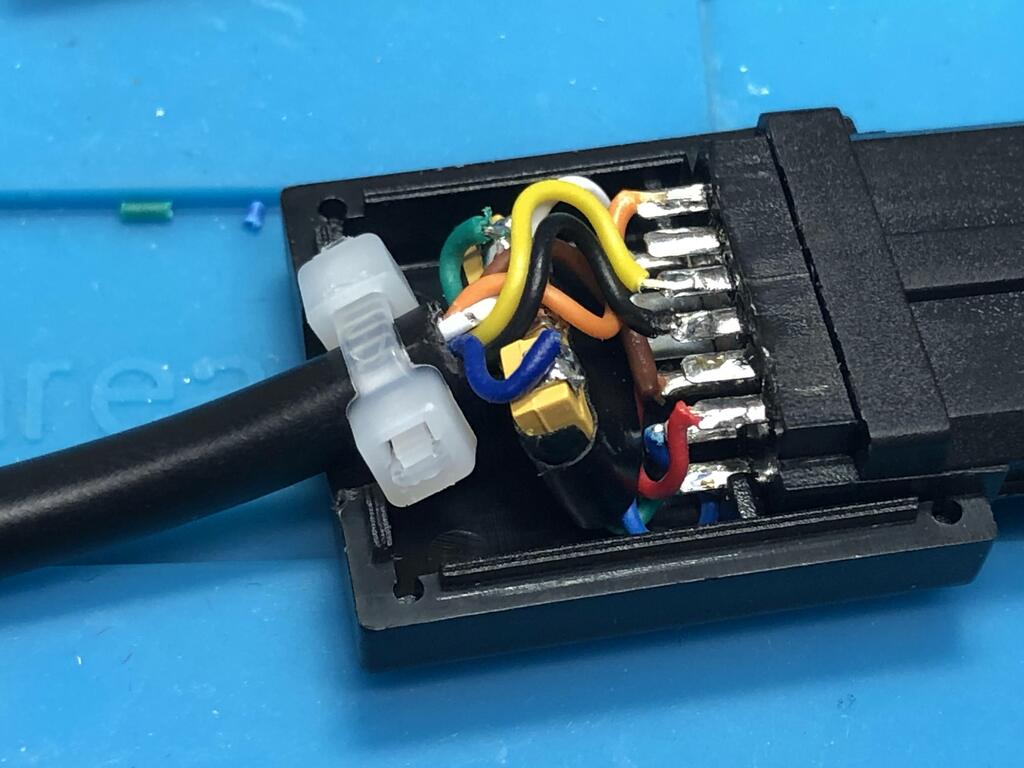
I must say, I was quite pleased at this point; however, after a bit of use, the colors started messing up, and wiggling the wire would sometimes restore it. So I took it apart, and tried something else.
Multiout End Attempt #2 #
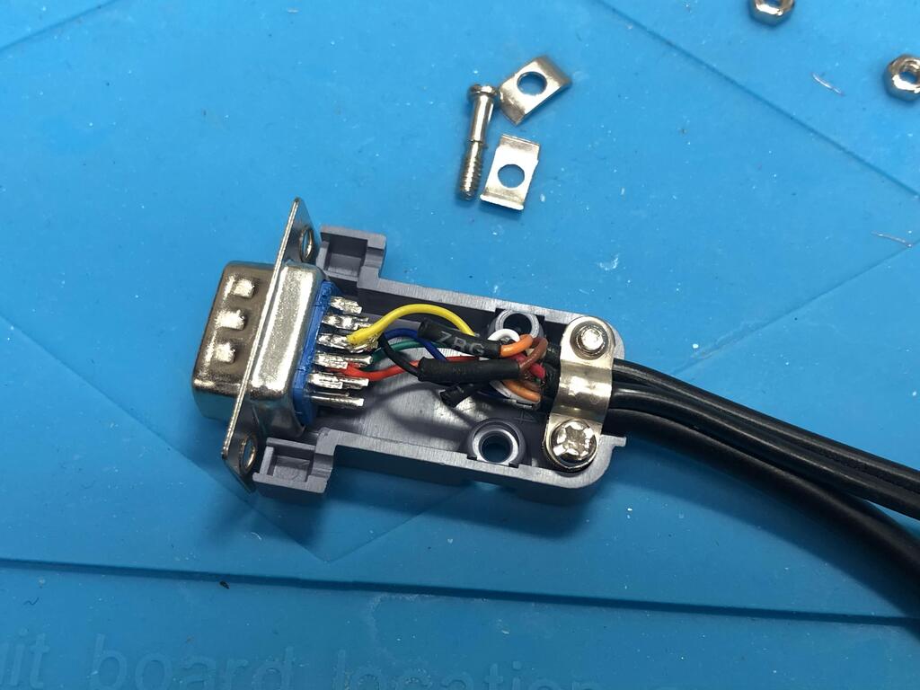
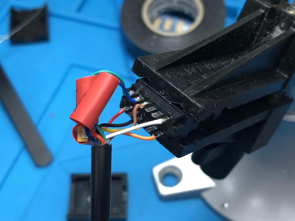
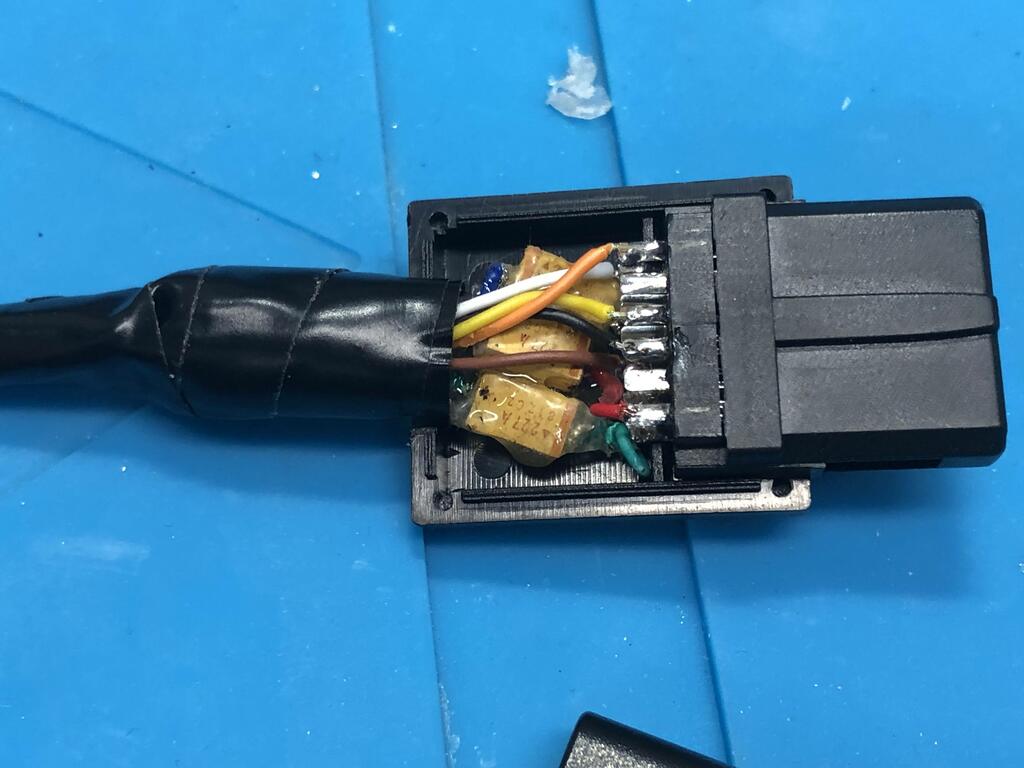
I figured that the reason the cables came undone might be because the caps were not really held well together (I was probably wrong about this, more on that later). So I used my least favorite tool, my glue gun, and ended up with this mess:
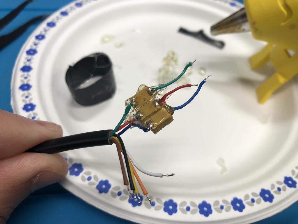
One good thing about the glue, I told myself, was that at least the exposed pads and wires would not be shorted against.
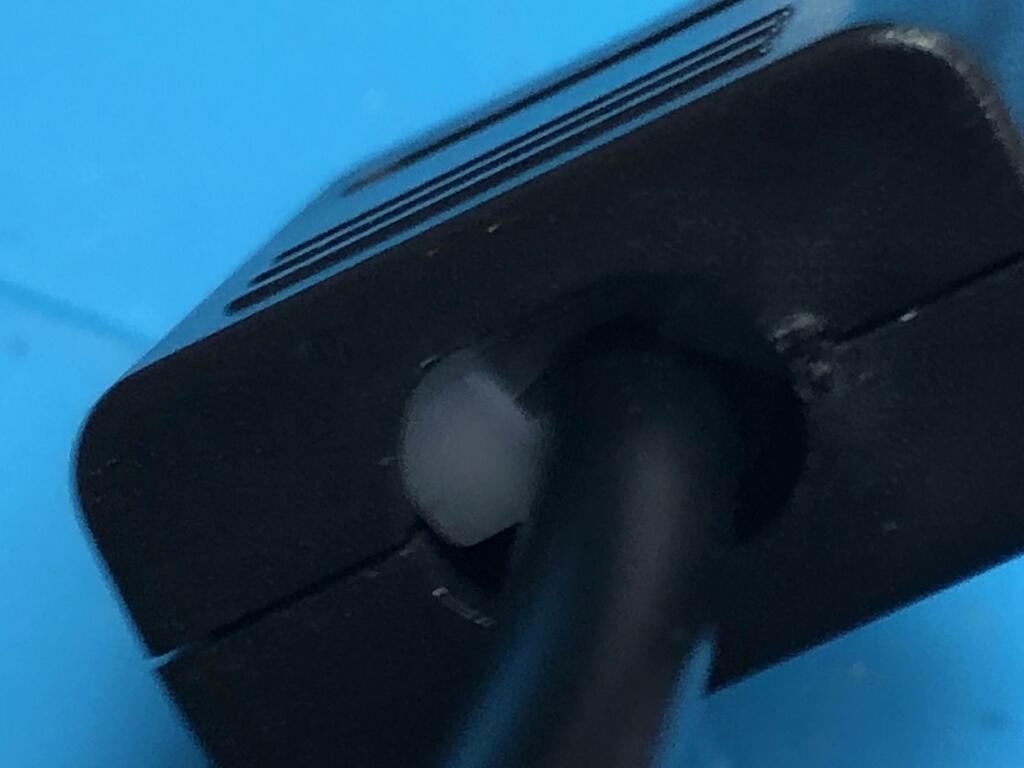
I also decided to forgo the clever dual tie-wrap strain relief, figuring it was just too tight in the shell, and that might have also contributed to the flakiness. Instead, I wrapped up the cable in loads of wire tape, until it fit very snugly into the shell:
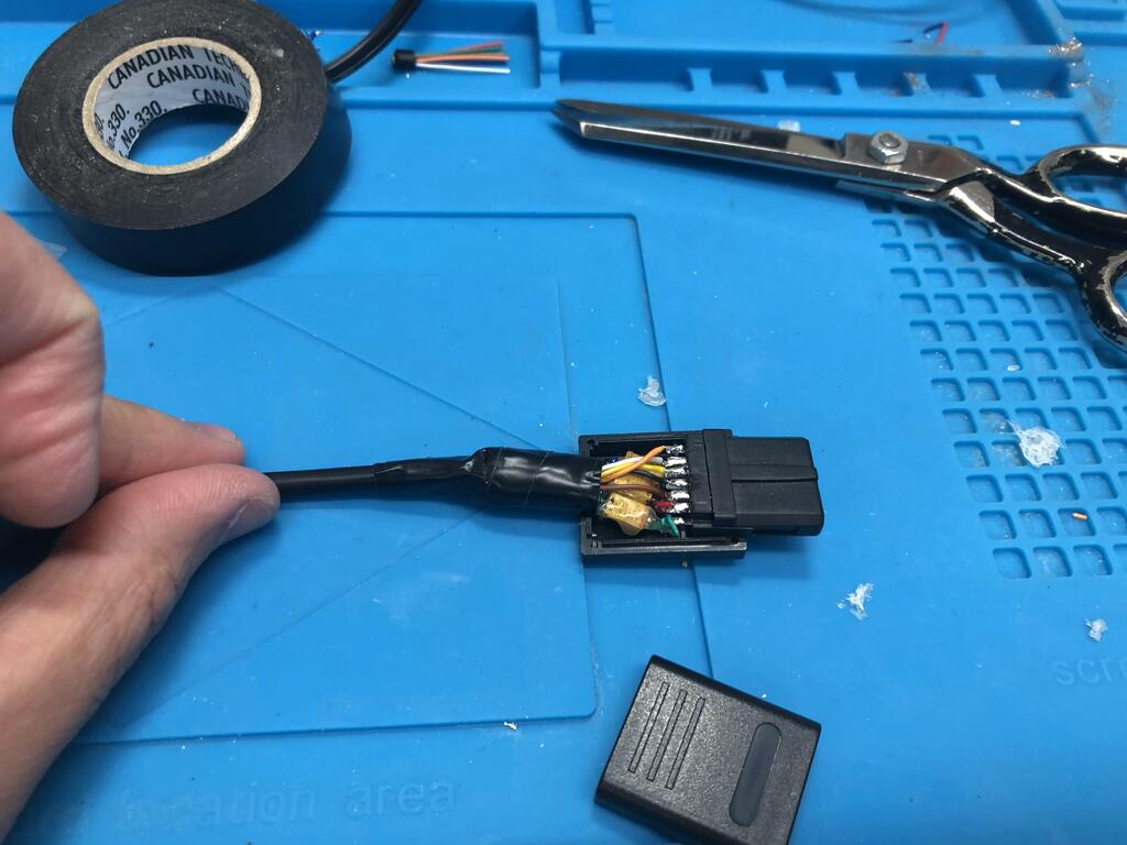
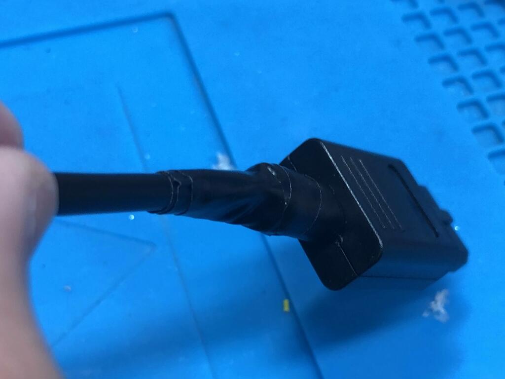
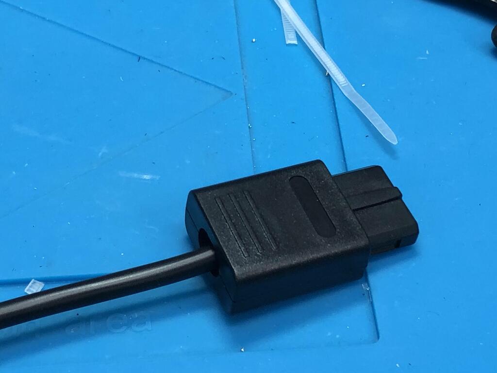
This is how my cable ended up. However, I will say that I really don’t like having this wire tape sticking out, and it doesn’t feel like a permanent solution, knowing that wire tape eventually softens and often comes unstuck after a while.
I think the real reason my first attempt failed was because I cut the RGB wires coming out of the cable too short - especially the red one. They were not long enough to allow for any movement of the cable. If I were to redo this, I’d go with my first attempt, but make the RGB wires longer, and maybe put hot glue around twist-tie end to make it thicker so that it doesn’t move as much inside the shell.
UPDATE 2022/09/29: I did eventually make a second cable that turned out much better! Check out my post about it here.
Results #
With the cable working, here are comparison shots of Mario 64 using the N64’s official composite cable going straight to my TV (left) vs the custom cable I made going to the TV via the gbs-control (right):
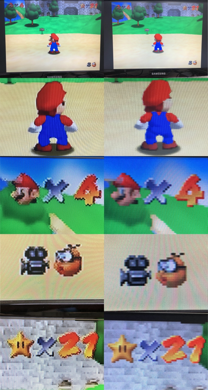
Keep in mind that the images above were taken with my phone camera of my TV screen, and then compressed, so it doesn’t really do it justice. However, you should notice how the typical composite signal artifacts are gone. In person, especially on my 70” TV, the quality difference is astounding.
Since I can use this same cable with an SNES, here are more comparison shots of Super Mario World:
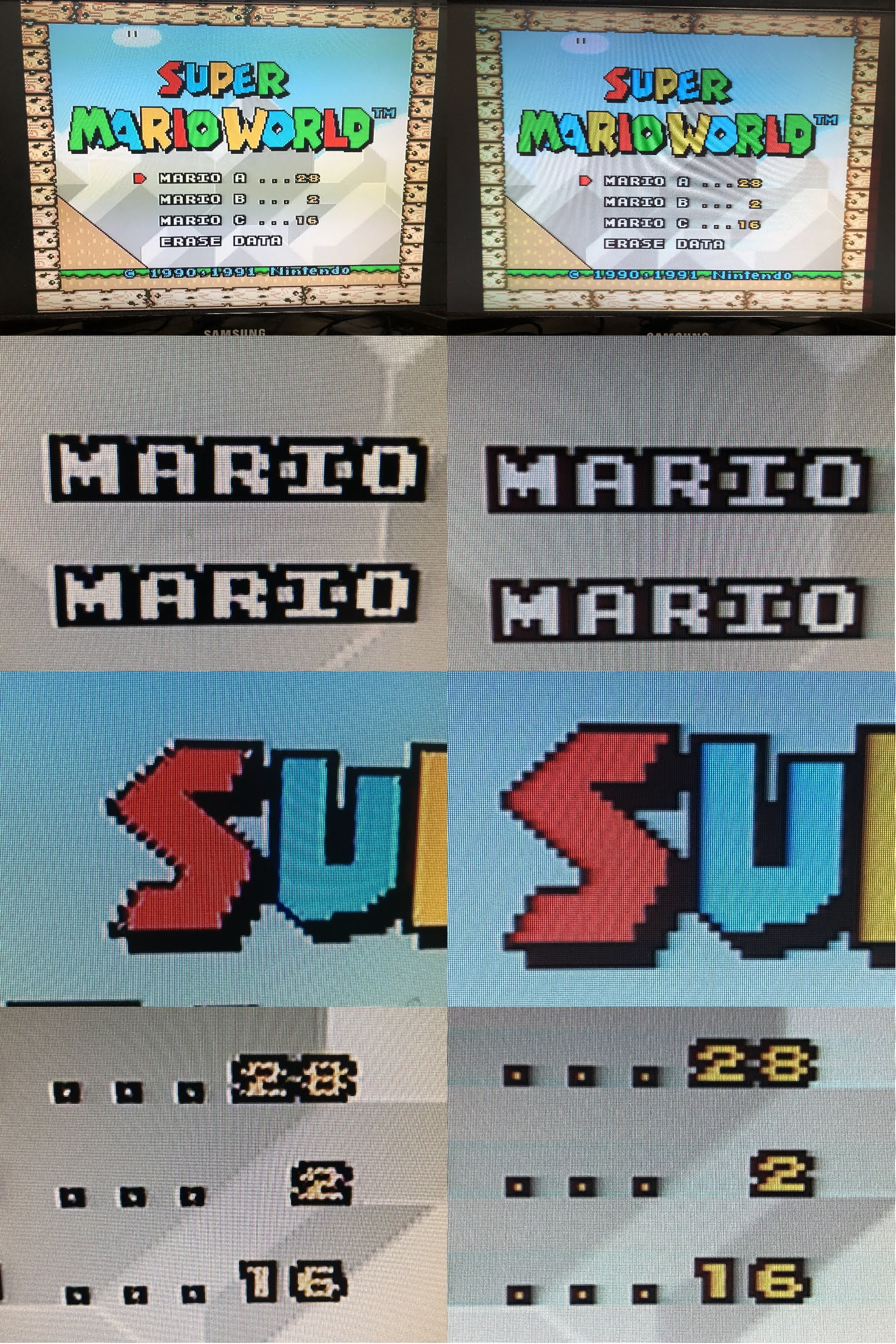
With a 2D game, the differences are even more obvious.
Thoughts #
I’ve been playing a bunch of N64 games since I made this mod, and I must say that I’m quite pleased with the results. The total cost for me was quite low, given that I could use a simple RGB board, and because I made my own cable.
The N64 RGB mod itself was very easy to do; however, making the cable was more challenging than expected because of the small multiout shell. One thought I had was sacrificing an original SNES/N64 composite multiout cable to be able to use the larger shell, but I’m not a fan of destroying original cables.
One other thing I would change is the length of the cable as it’s way too long. Instead of 5 meters, I would have been fine with 5 feet. I’ll probably cut it down to size someday, but so far it hasn’t been a real problem.
Anyway, to wrap this up, if you find yourself in a similar situation, I would definitely recommend this mod!